This article provides information (calculation, 3D models) about possible fatigue of details on the Very Large Gas Carriers (VLGS) in the modern LPG Industry.
Introduction
Objective of this assessment:
- To provide a comprehensive 3D FEM fatigue analysis of typical structural details of large LPG carriers.
Ship characteristics:
- LPG carrier – capacity 35 000 – 80 000 m3.
- Length over all 180 – 230 m (rules L > 170 m).
- Breath 30 – 37 m.
References:
- Bureau Veritas Rules for the classification of steel ships.
- Bureau Veritas note NI 393 DSM R01 Fatigue strength of welded ship structures.
- Guidelines ND350 rev. 02, for structural analysis of LPG carriers type A with prismatic tanks.
List of typical details candidates to fatigue assessment:
- Foot of main frames of side shell,
- Shell longitudinals with transverse webs,
- Knuckles between double bottom & hopper tank,
- Brackets in cargo tank,
- Supports and keys,
- Tank dome.
Role of supports and keys:
- To insulate the cargo tank, in order to insure an acceptable boil off rate, and to avoid that the temperature of the ship structure, in way of the supports & keys, is lowered below the values allowed for the steel used.
- To transmit to the hull structure the loads, corresponding to the weight supplemented by the dynamic effects due to the ship motions, while limiting the stress concentrations in both the hull and the cargo tank.
- To allow free contraction due to temperature, and free displacement between the cargo tank and the hold, due to the wave.
Methodology
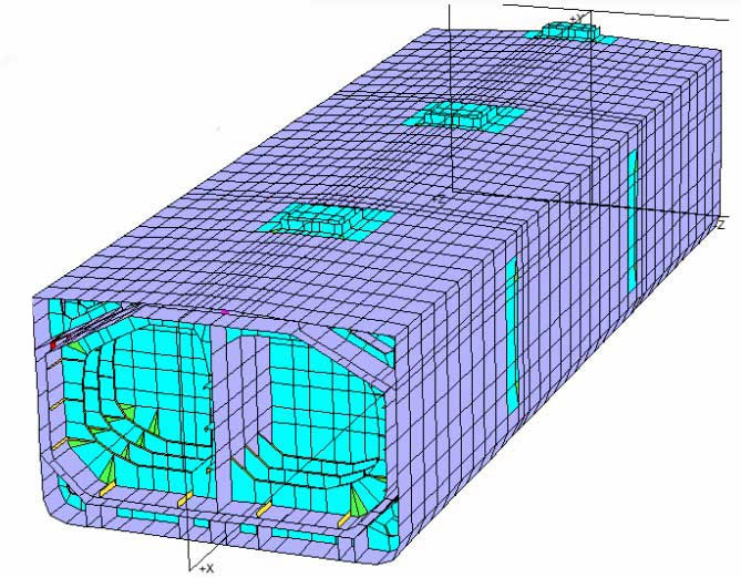
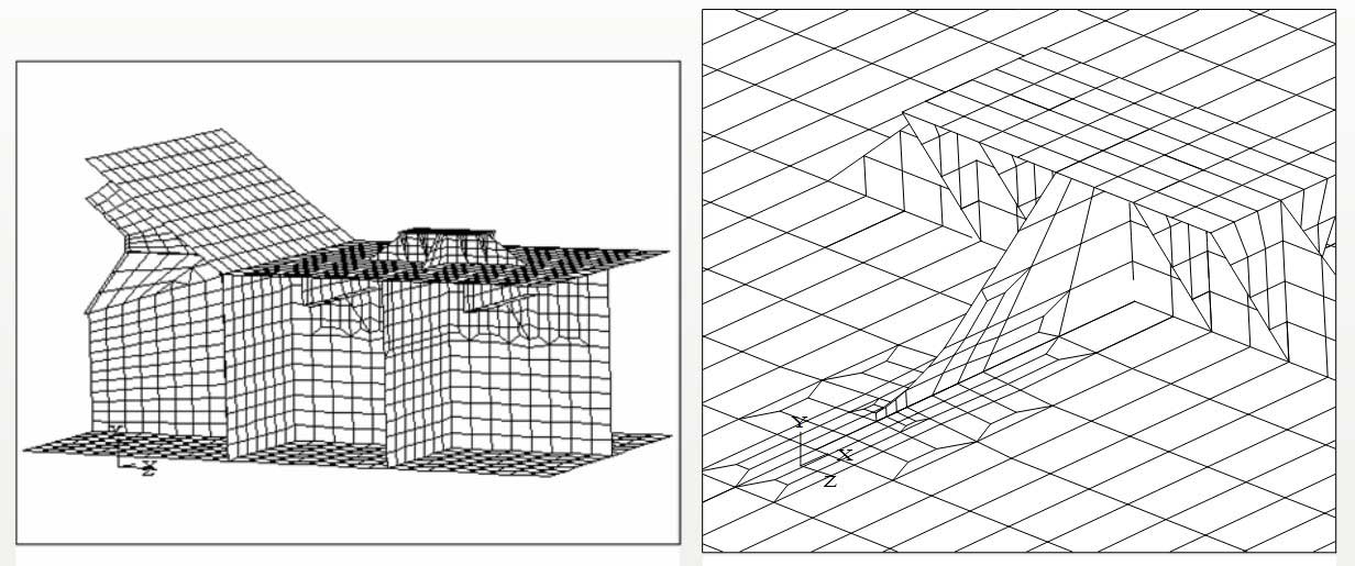
Veristar Model for fatigue analysis:
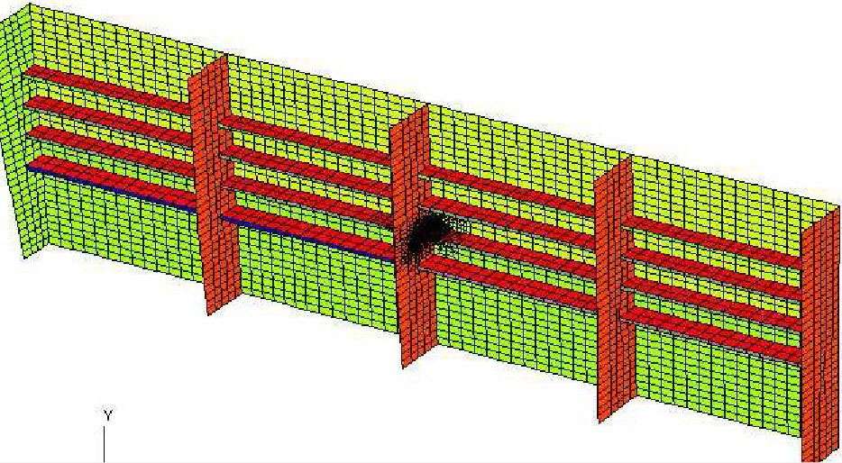
- 3D – Coarse mesh model (three holds model).
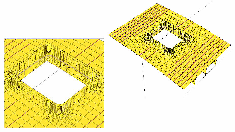
- 3D – Fine mesh for yielding assessment.
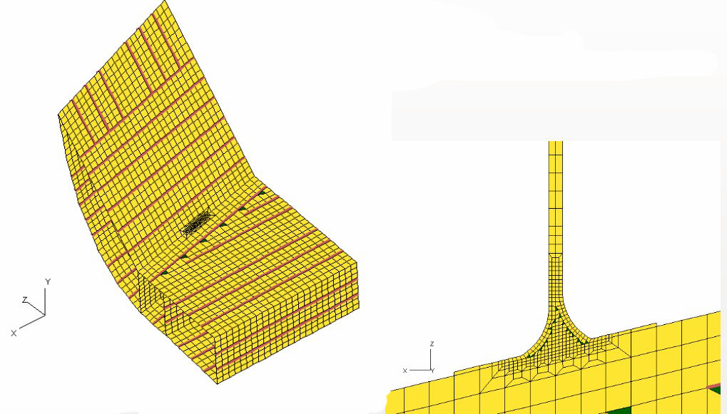
- 3D – Very fine mesh model (element size of hot spot = plating thickness).
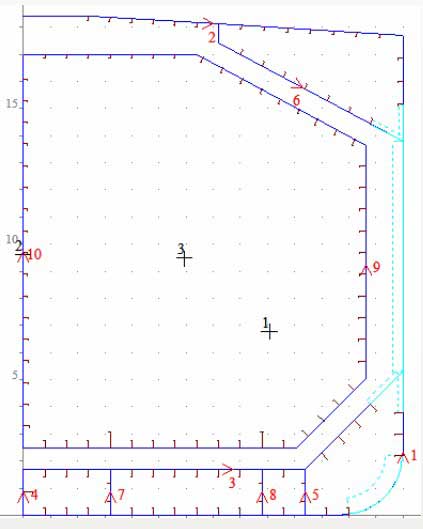
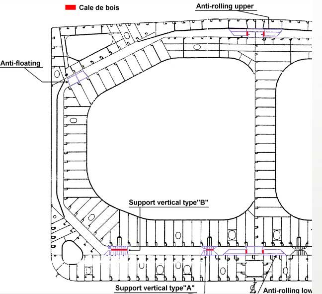
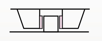
Supports description:
- Types of supports (model for each type).
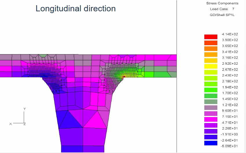
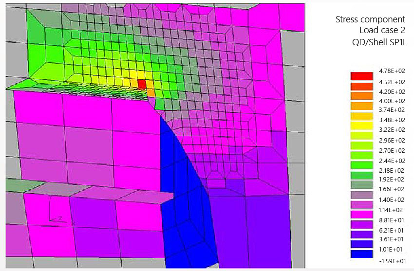
- Fatigue analysis in way of longitudinal and transverse directions.
- Fatigue analysis of supports in way of hull structure.
Structural Analysis
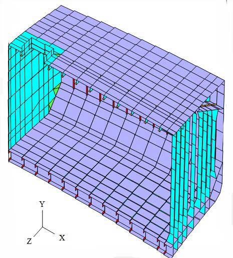
3D Calculation – Veristar Coarse Mesh aim at:
- Primary members in tanks and holds:
- Yielding.
- Buckling.
- Forces in the keys of the Tanks for supports assessment.
- Boundary conditions for fine mesh.

Method for calculation of the support stiffness.
Support stiffness to be taken into account in the model with Cargo tanks and hull structure.
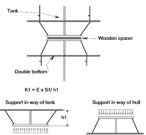
Vertical support
Fatigue calculation methodology
Assumptions for fatigue analysis:
- Sailing factor 0,85.
- Ship sailing 40 % Ballast and 60 % full load.
- Bureau Veritas design S-N curve based on British standard.
- Upright and inclined ship condition.
- Corrosion environment (not applicable in cargo hold).
Two approaches of fatigue assessment are possible spectral or deterministic analyses.
The deterministic approach using notch stresses, calibrated on results of hydrodynamic analysis is described hereafter.
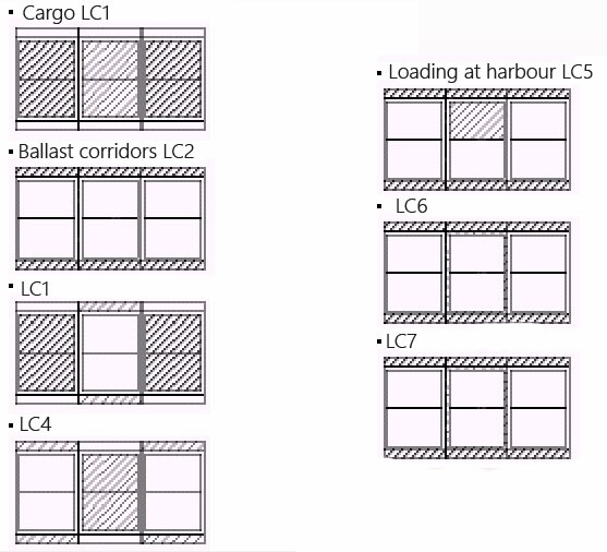
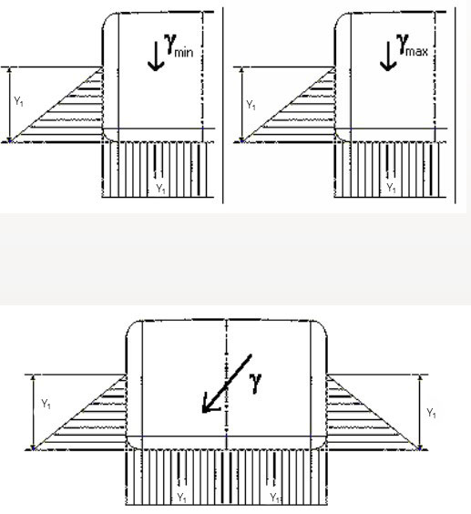
Load Cases
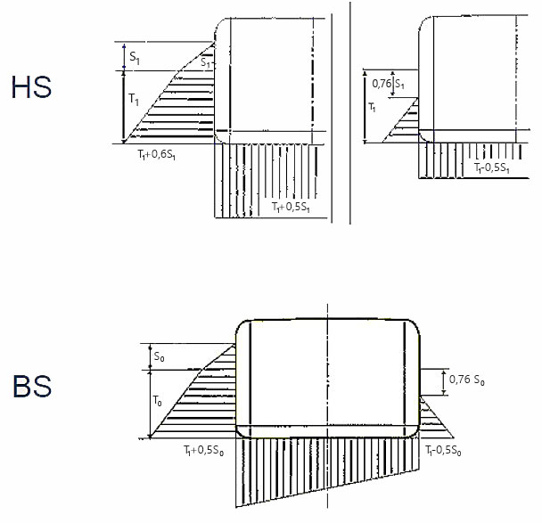
Sea Conditions
Fatigue assessment
Long term distribution of friction stress based on histogram for fatigue analysis.

Application to vertical supports
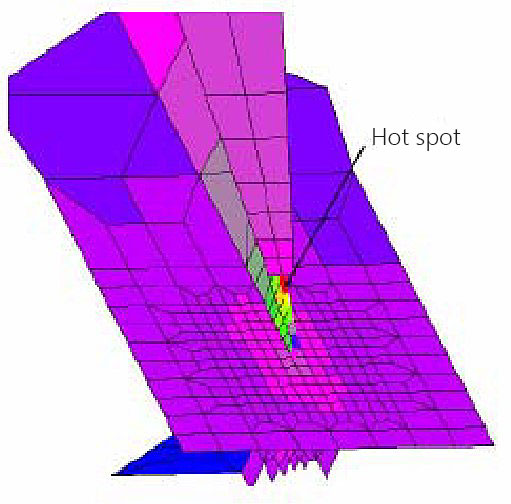
Fatigue assessment of vertical support.
Different steps:
- Step 1: Calculation supports merged (no sliding);
- Step 2: Calculation the probability level of sliding;
- Step 3: Calculation of supports in two parts (sliding);
- Step 4: A combination of damages obtained in steps 2 and 3 is carried out.
Friction Force:
- Only considered in full load condition;
- Implemented in longitudinal and transverse directions depending of the load case;
- Static friction coefficient is 0,3 whereas dynamic is 0,15.
- Fvertical assumed to be the main vertical force acting on supports.
Limit between static and dynamic friction.

Steps 1 & 2
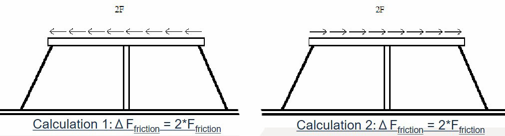
Friction Force:
- Load cases a&b -> Ffriction in longitudinal direction.
Load cases c&d -> Ffriction in longitudinal direction. - 2 calculations (the most conservative is used for fatigue).
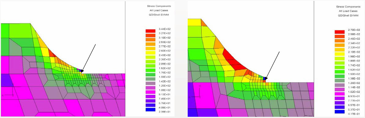
Step 3
Fatigue results considering a dynamic friction:
- Longitudinal support brackets.
Fatigue of keys
Fatigue assessment of anti-rolling keys.
The methodology is different between vertical supports and anti rolling keys due to gap in the key.
Due to this gap, the methodology includes the following steps:
- Step 1: Calculation without anti upper rolling key to define what probability level there is contact between anti-rolling keys;
- Step 2: Calculation anti-rolling key merged (contact);
- Step 3: A combination of damages obtained in steps 1 and 2 is carried out.


Other structural details
List of other details:
- Knuckles between double bottom & hopper tank;
- Shell longitudinals with transverse webs,
- Foot of main frames of side shell,
- Brackets in cargo tank,
- Tank dome.
| Configuration | KG | Configuration | KG |
|---|---|---|---|
 | Kgx = 2,0 |  | Kgx = 4,5 |
| Kgy = 3,85 | Kgy = 3,85 | ||
 | Kgx = 2,25 |  | Kgx = 5,6 |
| Kgy = 3,30 | Kgy = 4,5 | ||
 | Kgx = 1,75 |  | Kgx = 1,5 |
| Kgy = 3,55 | Kgy = 2,4 | ||
 | Kgx = 2,05 | ||
| Kgy = 3,15 | |||
Two stress concentration factors:
- Transversal (y): main effect.
- Longitudinal (x): secondary effect.
Conclusion
- Methodologies for fatigue assessment have been developed and are currently applied;
- Example of reinforcement/improvement based on the fatigue assessment:
- Brackets to be with soft toes, both in transverse and longitudinal directions;
- Locally grinding may be requested;
- For anti-rolling keys a gap is necessary;
- Local reinforcements are required based on fatigue assessment.