Discover how LNG carriers ensure utmost safety at sea with advanced fire prevention equipment. Explore innovative systems like water curtains, drenching systems, and fixed dry powder installations, meticulously designed to protect against potential fire hazards.
Learn about maintenance and testing protocols to uphold the reliability of these vital safety measures onboard vessels, ensuring secure transportation of liquefied natural gas.
Water Curtain
Reference: SIGTTO “LNG Shipping Suggested Competency Standards”, Sections:
1 Know and understand the purpose and principles of operation of the water curtain:
- operations requiring water curtain.
Operations requiring a water curtain
When any cargo operation is undertaken, the manifold water curtain should be activated from the period before the marine loading arm is connected until after it is disconnected.
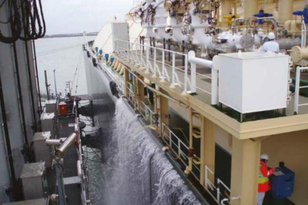
The curtain is supplied through the fire main. The water curtain creates a How to Prevent Fire and Explosion or How to Minimize Effects of itdeluge of water that is intended to protect the ship’s side from brittle fracture, should there be a leak of liquid LNG.
Drenching System
Reference: SIGTTO “LNG Shipping Suggested Competency Standards”, Sections:
1 Know the application and purpose of the drenching system:
- dedicated pump areas protected.
2 Know and understand the purpose and principles of operation of the drenching system:
- alternative pumping arrangements;
- maintenance;
- testing.
A water spray/drenching system supplies a cooling deluge of water over exposed surfaces. If a continuous layer of water can be provided by this system, the temperature of the surfaces will not exceed +100 °C.
IGC Code requirements
The IGC Code (11.3) requires that a water spray system is fitted. The system must be capable of covering all areas required with a uniformly distributed water application rate of at least 10 L per minute for the largest projected horizontal surface and at least 4 L per minute for vertical surfaces.
The capacity of the water spray pumps must be such that it is capable of simultaneous protection of the greater of either two complete athwartship tank groupings or any added fire hazard for special consideration and its adjacent tank grouping under 11.3.3. Alternatively, the main fire pumps may be used provided that their total capacity is increased. Water pumps normally used for other services may be arranged to supply the water spray system main line (11.3.5).
Dedicated pump
Typically, the dedicated water spray pump (IMO pump) is capable of delivering a water quantity capable of providing adequate coverage.
System overview
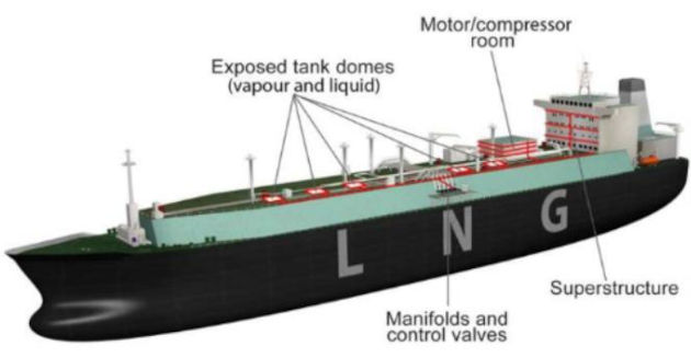
Locations requiring water spray protection:
- exposed tank domes and exposed parts of tanks;
- manifolds and control valves;
- exposed lifeboats, muster decks etc.;
- boundaries of superstruclures, deckhouses, compressor rooms, cargo pump rooms, store rooms with high fire risk and cargo control rooms facing the cargo area.
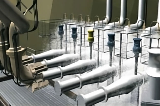
Nozzles
Nozzles are set approximately 800 mm apart and at 45° to the vertical. Headers are 250 mm from the bulkheads.
Areas protected
The drenching/water spray system is used to protect the following areas:
- accommodation front (typically 3 horizontal spray rails);
- cargo domes;
- cargo control room;
- cargo manifolds;
- fuel gas valves;
- all exposed ESD valves;
- lifeboat/liferafts and muster stations;
- satellite domes;
- gas/compressor house.
Alternative pumping arrangements
The water spray pumps, bilge, fire and general service pumps are located in the engine room. All take suction from the main seawater crossover pipe. Either the high or low sea chest must be open to this suction main at al I ti mes. The water spray system can also be supplied by the bilge, fire and general service pumps.
The pumps may be controlled locally, but they are normally operated from the IAS.
Read also: Fire Scenarios on liquefied gas carriers
The water spray system should be available for use at all times. It should be available for starting, either locally or remotely from the IAS, and able to deliver water to all the water spray nozzles on deck.
Maintenance and testing
The system is equipped with drain connections located at main deck level below the manifold area and the cargo machinery room.
The water spray pump can also be cross connected onto the fire main in an emergency. The crossover is located in the engine room. Under normal circumstances this valve is kept locked shut.
The Fire protection and Fire extinction on Liquefied Gas Carrierswater spray drenching system is flushed with fresh water after use by cross connecting the bilge/fire and general service pump to the suction from the fresh water tanks.
System testing is logged and documented at intervals as defined in the company planned maintenance system (PMS). When it is tested it is customary to have enough people involved, wearing appropriate PPE, so that all sections of the system can be sighted to note any leaks or blocked nozzles. Maintenance will be based on the outcome of the test.
Fixed Dry Powder Installations
Reference: SIGTTO “LNG Shipping Suggested Competency Standards”, Sections:
1 Know the operation and application of the fixed dry powder fire-fighting system.
2 Know and understand the maintenance and testing of the fixed dry powder installation:
- operating systems;
- distribution equipment.
LNGCs must be fitted with a fixed dry powder installation capable of fighting fires on the cargo deck area. However, it should be remembered that extinction of a major gas fire is not recommended unless the source of gas is secured.
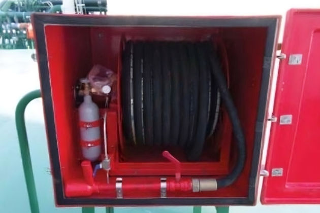
At least two hand hose lines should be provided to cover the cargo deck area. In practice, on a large LNGC, there will be two systems with monitors either side covering the port and stbd manifolds and 10-12 hose cabinets strategically situated around the deck.
| Discharge capacity | Effective coverage distances | ||
|---|---|---|---|
| Hand hoses | 3,5 kg/sec | Hand hoses | 30 m (hose length) |
| Manifold monitors | 15 kg/sec | Monitor nozzle | 17 m |
| Note: both must be capable of operation for a minimum discharge period of 45 seconds. | |||
The dry powder installation can be operated from the individual stations (either hose box or manifold monitor) or activated remotely from the CCR or fire control station.
Each system consists of a tank containing sodium bicarbonate and cylinders containing N2 gas under pressure. The system is operated by releasing the N2 gas into the tank, which forces the mixture of powder and N2 gas through the pipelines to the monitors and hose cabinets. The discharge valves on the N2 gas cylinders are designed to be opened manually or by CO2 gas pressure from the remote release control cabinet bottles.
Remote release cabinets for the system are typically found at the following locations:
- cargo control room;
- fire control station.
The reaction from a hose nozzle discharging at high pressure will be severe and the operator should be trained in its use. The handheld gun type applicator is preferred to a nozzle and valve and the actuation of such a unit normally requires two people working as a, team. Where powder monitors are mounted on the ship, the design should be such that the nozzle recoil is taken up by the monitor mounting.
When attempting to knock out the fire using a powder system, it is important to decide whether or not the water spray system should be cut off before the powder strike.
With a fire burning and the water sprays in action, the cooling effect of the water can create dense clouds around the fire, obscuring its seat. Should the water be turned off, the fire may burn off and reveal the seat of the flame allowing a better target at which to aim. Dry powders based on sodium bicarbonate are normally projected at the base of the fire, but such powders are soluble in water and a proportion may be eliminated if they must pass through a water curtain. Powders based on potassium can be more effectively shot through a water curtain. It should be noted that dry powders provide no cooling effect and may be ineffective since a fire extinguished by dry powder can easily reflash from the hot metal. With liquefied flammable gases this is always a possibility.
Procedure for operating the dry powder system from a hose or manifold monitor cabinet:
The monitor’s dry powder supply valve should be open and the monitor should be secured in a position to direct the dry powder towards the manifold couplings, as this is the most likely area for a gas leak and subsequent fire.
- Open the door containing the CO2 pilot gas cylinders that activate the N2 cylinders;
- open the discharge valve on one of the CO2 gas cylinders;
- aim the hand hose nozzle at the fire and open the nozzle valve.
Note: in the event that the system fails to discharge the dry powder, manually open the N2 cylinders and discharge valve.
Maintenance and testing of the fixed dry powder system
The dry powder system should be maintained and tested regularly as per:
- company planned maintenance system (PMS) requirements;
- manufacturer’s requirements;
- any Class/flag State requirements.