This article covers the following learning outcome: outline appropriate control measures to minimize the effects of fire and explosion, methods of protection from fire, detection systems etc., in the oil and gas industries.
- Leak and fire detection systems
- Introduction
- Detection systems
- Other design considerations for alarm systems
- Passive fire protection
- Introduction
- Types of passive fire protection
- Aims of passive fire protection
- Types of fire
- Coding of fire walls
- Active fire protection systems – water based extinguishing systems
- Water deluge systems
- Sprinkler systems
- Active fire protection systems – chemical/foam based extinguishing systems
- Foam based extinguishing systems
- How foam is made
- Controlling effects of foam
- Polymer film additives
- Chemical fire extinguishing systems
- Fixed dry chemical powder fire extinguishing systems on bulk gas carrying ships
- Active fire protection systems – inert based extinguishing systems
- Inert gas systems
- Water mist systems
- Examples of equipment-specific types of fire protection systems and their functions
- Floating roof tanks
- Fire protection systems for spherical storage tanks
- Gas turbine systems and compressor systems
- REVISION QUESTIONS FOR ELEMENT 4
Leak and fire detection systems
Introduction
All process plants, refineries, storage facilities, etc. related to the oil and gas industry should be designed to be as safe as possible. However, no matter how comprehensive the design is, there will always be a residual risk. Consequently, everything possible should be done to mitigate the consequences of any untoward incident, particularly those involving fire or explosion.
The risk of fire and/or explosion on installations carries the highest level of consequence and, as such, needs to be addressed as robustly as possible.
This is generally done by designing into the installation a series of protective layers, of which there are usually three:
- A detection system to warn of any fire or the potential for fire, such as a leak of product, smoke or an increase in localized heat;
- An active layer which aims to deal directly with any outbreak of fire, such as a water deluge system;
- A passive barrier which aims to limit the extent of any fire, whilst the active barrier does its job.
We will now look in detail at all three layers.
Detection systems
As we have just mentioned, detecting, controlling and managing leaks, fires and explosions is the first layer of protection from the consequences of fire or explosion. The Fire and Gas (F&G) detection system is a combination of various devices strategically positioned throughout the installation which aim to give the earliest possible warning of any potential problem that could escalate into a fire or explosion if it is not dealt with as quickly as possible.
We are now going to look at the various leak and fire detection systems, including:
- Spot systems;
- Flame detection systems;
- Heat detection systems;
- Gas detection systems;
- Smoke detection systems;
- Leak detection systems.
Detection systems – spot systems
Spot fire detection systems are designed to conduct a continuous thermal surveillance of a specific area. They are sensitive to infrared radiation within a cone of vision.
The extent of the cone of vision, and consequently the area being protected, can vary and is dependent on the model and manufacturer.
Spot fire detection systems are extremely sensitive and are capable of detecting changes in temperature of less than 1 °C, although this level of sensitivity can be set to suit individual requirements. This enables the fire and gas system to be forewarned at a very early stage of any potential overheating or fire risk, provided it is within the camera’s cone of vision.
Detection systems – flame detection systems
Over and above the heat detection systems we have just covered, there are other systems which are capable of detecting flames.
They include:
- Camera-based flame detectors;
- Ultraviolet flame detectors;
- Combined ultraviolet and infrared flame detectors.
We’ll now take a brief look at each of these systems to see how they work.
Camera-based flame detectors
Camera-based flame detectors are capable of detecting and pinpointing a fire from long distances as soon as the fire starts. These pictures can be relayed back to the control room operator. A camera-based flame detector can give control room operators real time information about the state of the fire.
These detectors can also make a recording of events prior to the incident. This facilitates a full evaluation of the circumstances surrounding the incident so that proper and appropriate actions can be taken to reduce the risk of a Investigating Incidents, effective identification of the root causes and making recommendations for improvementrepeat incident.
These types of camera can cover very large areas, which mitigates their cost compared with other fire detection technologies.
Ultraviolet flame detectors
Ultraviolet flame detectors were the original type of flame detector and have mostly been replaced by more advanced technologies. They rely on detecting the ultraviolet radiation produced by flames. However, the more advanced ultraviolet flame detectors are capable of detecting hydrogen fires and, as such, can have a part to play in some fire and gas detection systems.
Combined ultraviolet and infrared flame detectors
These detectors are capable of detecting both ultraviolet radiation and infrared radiation. They tend to be used where the reduction of false alarms is an issue.
Detection systems – heat detection systems
There are two types of heat detector:
- Point heat detectors;
- Linear heat detectors.
We’ll now take a brief look at each of these systems to see how they work.
Point heat detectors
These systems are capable of detecting a rise in temperature at any point within the range of the detector. There are two types of point heat detectors known as “rate of rise” detectors and “fixed temperature” detectors. The rate of rise detector monitors the ambient temperature with a view to detecting any sudden increases in temperature, whilst fixed temperature detectors are set to respond when a preset temperature is reached.
Examples of where they might be used include:
- Kitchens;
- Turbine hoods;
- Pump buildings;
- Generator hoods;
- Where use is mandatory through legislation or codes of practice.
Linear heat detectors
Linear heat detectors are used where heat detection is required in a linear fashion, for example on tank rim seals or in cable tunnels. They are capable of detecting a fire anywhere along its length.
The linear heat detector comprises a cable which is made up of a pair of twisted wires which are each sheathed in a polymer coating. This coating is engineered to break down at a specific temperature (a full range of temperatures is available to suit varying requirements). If heat or flame melts the polymer coating, this allows the twisted wires to make contact and send a signal to the alarm box and/or control room.
Detection systems – gas detection systems
Gas detection systems are capable of detecting a discharge of combustible or toxic gas. If combustible gas is detected, they will warn the control room of the incident and may well initiate action from the fire and gas system to control and minimize the leak and prevent it from developing into a fire or explosion.
If a toxic gas is detected, they can warn personnel of the hazard in the area.
There are a number of different types of gas detector available. These include:
- Infrared absorption combustible gas detectors;
- Point infrared gas detectors;
- Open path infrared gas detectors.
We’ll now take a brief look at each of these systems to see how they work.
Infrared absorption combustible gas detectors
Infrared absorption combustible gas detectors work by being able to recognize the specific absorption characteristics that hydrocarbon molecules have to infrared light. The more hydrocarbon molecules that are present in a given space being monitored by these devices, the higher the absorption of infrared radiation. These devices are capable of detecting more than one type of hydrocarbon gas.
Point infrared gas detectors
Point infrared gas detectors monitor a specific location with the aim of measuring the concentration of gas at that location. Consequently, they need to be positioned where a release of gas is considered possible or where gas is considered to be especially problematic, for example the air inlets to temporary refuges.
It is possible to position them remotely and then connect them by tubes to the location requiring monitoring.
Air can then be drawn from the sampling location and passed over the detection chamber within the device.
Examples of use are:
- Detection in confined spaces;
- Specific locations;
- Air inlets into accommodation (e. g. temporary refuge).
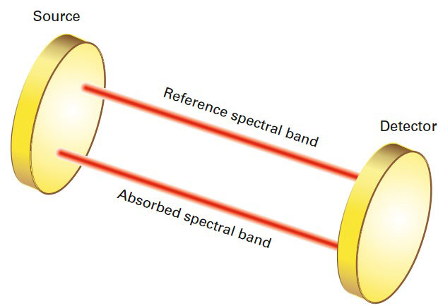
Open path infrared gas detectors
Open path infrared gas detectors are made up of two components, a transmitter and a receiver, as shown in Figure 1. They constantly monitor the area between these two components to detect the presence of any gas.
Source: Wise Global Training
They work on the principle of sending two infrared beams between the transmitter and the receiver. The first, a sample beam, is the infrared beam which is set to detect the presence of hydrocarbons. The second infrared beam is set so that its wavelength is outside the gas absorbing range. The two beams are constantly compared and whilst the comparison remains the same as the factory setting, no gas is present and no alarm is raised. However, if the comparison changes because some of the sample beam has been absorbed by gas, the device will trigger an alarm.
These devices can detect more than one type of hydrocarbon gas and different versions can also detect hydrogen sulphide (H2S).
When a gas cloud crosses the sample beam, the ratio of the two beams changes and this is detected by the system and automatically raises the alarm.
Figure 2 shows an open path infrared gas detector units in situ.
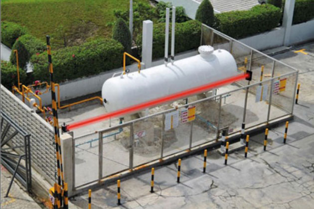
Source: Dreamstime
In this case, the infrared beam has been artificially superimposed in order to highlight its location.
Detection systems – smoke detection systems
Smoke detectors range from the battery-powered detectors of the type used in the home, to sophisticated camera-based detection systems.
They include:
- Point smoke detectors;
- Ionization point smoke detectors;
- Optical point smoke detectors;
- Optical beam smoke detectors;
- Aspiration smoke detectors.
We’ll now take a brief look at each of these systems to see how they work.
Point smoke detectors
Point smoke detectors are designed to detect smoke at a fixed location. Ideally, they should be positioned where smoke is most likely to accumulate in the event of a fire.
Examples of use are:
- Offices;
- Corridors;
- Switch rooms;
- Accommodation.
Ionization point smoke detectors
An ionization point smoke detector uses a small radioactive source (a radio isotope) to ionize air inside a detection chamber. Any change in this ionization, due to the presence of smoke particles, will activate the alarm.
In comparison with optical detectors, ionization detectors are more sensitive to the stage of a fire where flames are present, whereas optical detectors are more sensitive to fires when they are still smouldering.
Example of use are:
- Where there is the potential for high energy fires Where use is mandatory through legislation or codes of practice.
Optical point smoke detectors
Optical point smoke detectors are designed to detect smoke particles inside a sampling chamber. This is where a source of light is collimated into a beam and a photoelectric sensor is set at an angle to the beam to act as a light detector and monitor it. In the absence of smoke, the beam continues to be emitted in a straight line. However, if smoke particles are present, some of the light is scattered and the light detector senses this and triggers the alarm.
They tend to be used for general purposes but versions which are set to be highly sensitive can give early warnings where this is a requirement.
Optical beam smoke detectors
Optical beam smoke detectors work on the principle of measuring any difference in light emitted from one point and received at another point. Where smoke particles absorb or scatter the light, this is detected and the alarm is triggered.
Optical beam smoke detectors come in two variations – end to end optical beam smoke detectors and reflective optical beam smoke detectors.
End to end optical beam smoke detectors have a separate light transmitter and receiver, whereas reflective optical beam smoke detectors have the light transmitter and receiver within the same unit. The light path is directed from the transmitter to a retro reflector positioned some distance away. The retro reflector then sends the light beam back to the receiver and a comparison is made.
Note: A retro reflector is like a mirror which reflects light to a given location with the minimum of scattering.
Examples of use are:
- Monitoring of large areas, e. g. atria, machinery spaces, etc.;
- Areas where it is impractical or impossible to mount other types of detector.
Aspiration smoke detectors
Aspiration smoke detectors use a network of tubes to draw samples of air from various locations to a central detection unit. This detection unit then looks for the presence of smoke particles by measuring whether light passed through the samples is scattered or not. If it is scattered, this indicates the presence of smoke and the alarm will be triggered.
Detection systems – leak detection systems
Leak detection systems work on the principle of detecting the ultrasonic sound emitted when a leak of gas or vapour occurs from a small gap, such as those that may develop on valves, flanges and joints in pipework. This sound is inaudible to the human ear but is highly characteristic when gas or vapour leaks from the gap in the plant.
These devices are not limited to any particular gas or vapour, as all gases and vapours emit similar ultrasonic sounds, which makes these devices useful as general gas or vapour leak detectors.
Other design considerations for alarm systems
Now we’ve looked at the various types of alarm systems available to those who design protective and pre-emptive warning systems into installations, we now need to look at other aspects to be taken into account at the design stage.
Buildings, plant and equipment layout tend to be divided into three categories as far as fire and leak safety engineering is concerned.
These are:
- Fire compartments;
- Detection zones;
- Alarm zones.
We will now take a more detailed look at each of these types of zone and see how they affect design decisions.
Design considerations – fire compartments
Buildings are generally divided into sections, known as fire compartments, which use fire resistant structures (walls and floors) to enclose them in order to limit the spread of any fire that may break out within any one of these sections.
It is necessary for the designer of fire detection and alarm systems to be familiar with the design and structure of the building and plant and, in particular, the position and extent of its fire compartments.
Design considerations – detection zones
Detection zones are essentially a convenient way of dividing up a building, area or plant into manageable sections so as to assist in quickly locating the position of any fire or leak.
The zone boundaries do not necessarily have to be physical features of the building, although it is normal practice to make the zone boundary coincide with walls, floors and specifically fire compartments.
The size and position of the detection zones will be more dependent on such things as the extent of areas used for one particular process or the number of people working in one section at a time.
Design considerations – alarm zones
Complex buildings, where it is necessary to operate alarm devices differently in various parts of the building, should be divided into alarm zones so that all of the alarm devices in one alarm zone operate in the same way.
Separate alarm zones are only necessary if different alarm systems are needed in different parts of the same building. If the only requirement is to activate all the alarms in order to provide a single common evacuate signal once a fire is detected, then alarm zones are not needed. The whole building is regarded as one alarm zone.
Alarm zones are not constrained by the extent of detection zones. Alarm zones may contain multiple detection zones.
Passive fire protection
Introduction
As a general term, passive fire protection covers the materials, products and design measures built into a building or structure in order that any fire which may start in the building or structure is restricted in its growth and spread. This is achieved by controlling the flammability of the structure, including:
- walls,
- ceilings,
- floors,
- doors, etc.,
as well as by protecting structural steel members from severe heat which might compromise their integrity. Finally, the building or structure is designed in a way that divides it into separate fire containing compartments. This is so that any fire which may start will be restricted, or contained within a limited area.
More specifically, Passive Fire Protection (PFP) can be described as a coating, cladding or free standing system which will act as a thermal barrier to restrict the rate at which heat is transmitted to any object or adjacent area.
The type and extent of PFP will depend on a number of factors, including:
- The type of fire anticipated – hydrocarbon jet or pool fires, or cellulosic fires;
- The expected maximum duration of fire;
- The consequences if the Passive Fire Protection (PFP) is breached.
Types of passive fire protection
There are many types of Passive Fire Protection (PFP) materials available. These can be broadly categorized as follows:
- Spray-applied coatings;
- Blanket/flexible jacket/wrap around systems;
- Prefabricated sections such as walls;
- Enclosures and casings Composites;
- Seals and sealants;
- Systems (e. g. cable transit blocks, inspection hatches, pipe penetration systems through bulkheads).
On offshore installations, where weight is at a premium, spray applied coatings are the most frequently used type of passive fire protection.
Aims of passive fire protection
Passive fire protection has three main aims:
- To prevent steel structures, which are load-bearing, reaching a temperature where their integrity will be compromised. This is generally accepted as being 400 °C.
- To protect process vessels and their supportive structures (legs).
- To prevent heat transfer through walls, floors and ceilings into adjacent rooms or spaces by limiting the inner wall temperature to no more than 180 °C in any one location.
Types of fire
Fires can be categorized as being either cellulosic or hydrocarbon. This refers to the fuel which is being consumed by the fire.
Cellulosic fires are those which burn materials such as timber, upholstery or paper. Hydrocarbon fires are those which burn oils and fuels.
Hydrocarbon fires burn much more fiercely than cellulosic fires. Consequently, Passive Fire Protection (PFP) used in buildings or structures associated with hydrocarbons should be of a higher performance standard than PFP used where the only fire threat is from cellulosic material.
Coding of fire walls
Walls and divisions which have been manufactured as passive fire protection are coded in relation to the type of fire they are designed to withstand and its duration. The code is made up of a letter (either H or A) followed by a number (0, 30, 60 or 120).
The letter indicates what type of fire the wall or division has been made to withstand. “H” type fire walls are manufactured to a standard that will withstand hydrocarbon fires, whereas “A” type fire walls are manufactured to a standard that will only withstand cellulosic fires.
The number which follows the letter indicates the length of time the wall or division has been designed to hold back the fire.
For example, a wall with a “H60” coding is designed to withstand a hydrocarbon fire for 60 minutes, whilst a wall with an “A30” coding is designed to withstand a cellulosic fire for 30 minutes.
Active fire protection systems – water based extinguishing systems
Active fire protection systems are those fire protection systems which are primed and ready to be activated on a given signal.
Water deluge systems
We have covered water deluge systems in Safety Critical Equipment Controls in Oil and Gas Industry this article, but in respect of active fire protection systems, it’s worth reiterating the issue.
A water deluge system is a means of fighting a fire with large amounts of water. It is generally positioned in areas where hydrocarbons are processed or stored, as well as areas where there is the potential for an uncontrolled release of gas which could result in a fire or explosion.
It works by means of a series of nozzles connected to a piping network. The nozzles are kept permanently in the OPEN position. When an emergency situation arises, the deluge system is activated by the Emergency Shutdown (ESD) system. This switches on the dedicated fire water pumps, resulting in water being emitted from the nozzles and deluging the area.
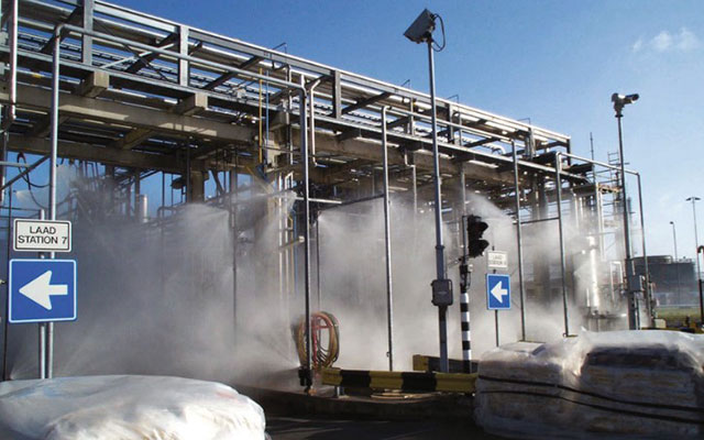
Source: Frontline Fire International
A deluge system can be activated by the emergency shutdown system or manually.
Water deluge systems provide a broad level of protection against a wide range of fire scenarios. This includes offering protection to open or unshielded escape routes.
When activated, deluge systems swamp the target area with water. As well as having a cooling effect on the fire, they also starve the area of oxygen.
Water deluge systems are highly effective when dealing with pool fires, especially when used in conjunction with aqueous film forming foam (AFFF). However, they have a limited effect when required to deal with jet fires, especially those which have high combustion rates.
Sprinkler systems
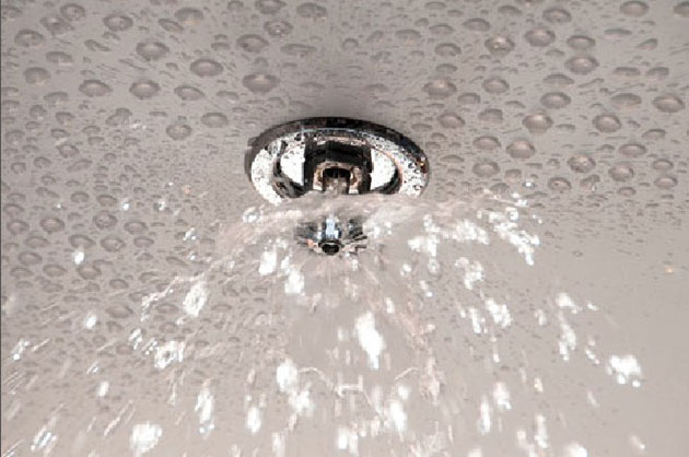
A fire sprinkler system is an active water based fire protection system consisting of a grid of water pipes, usually located within a roof void, which has sprinkler heads located at regular intervals which protrude through the roof. The sprinklers are spaced in such a way as to give adequate cover to the whole area which needs protecting against the outbreak of fire.
The water in the pipe system remains under pressure (active) but is held back at each sprinkler head by a thermal element. When a thermal element is activated because it has reached its predetermined temperature, it allows water to be sprayed from that sprinkler head. Only sprinkler heads in the vicinity of the fire will be activated, thus ensuring only the immediate area around the fire is sprayed with water. This minimizes any possible water damage.
Sprinkler heads can also be placed in remote areas, such as roof voids and floor ducts where fires may start unnoticed.
The sprinkler head shown in Figure 4 has a glass bulb as its thermal element.
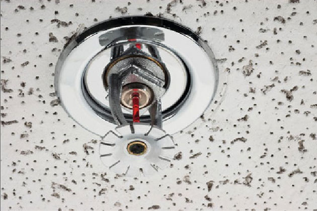
Source: iStock.
When the bulb experiences a level of heat equal to its predetermined setting, it will shatter, allowing water to be sprayed. Sprinkler heads operate individually.
Source: iStock.
Active fire protection systems – chemical/foam based extinguishing systems
Foam based extinguishing systems
Foam is used as a means to extinguish liquid fires. It has four useful characteristics which make it a suitable medium for fighting liquid fires:
- It excludes air from the flammable liquids – it takes oxygen out of the fire triangle;
- It eliminates vapour release from the fuel surface – it takes fuel out of the fire triangle;
- It separates the flames from the fuel surface – it takes heat out of the fire triangle;
- It cools the fuel surface.
How foam is made
Foam is made by combining water with a foam concentrate and mixing it in a way that introduces air. It is basically a stable mass of small air-filled bubbles with a density which is lower than oil or gasoline. This means it will readily flow over the surface of burning fuel.

Source: Elgin Air Force Base.
When mixed, foam expands at different rates according to the concentrate used. Low expansion foams, such as Aqueous Film Forming Foam (AFFF) have an expansion ratio of less than 20 times.
Medium expansion foams have an expansion ratio of between 20 and 200 times.
High expansion foams have an expansion ratio of over 200 times. They tend to be used for quickly flooding large enclosed areas.
Controlling effects of foam
Foam can apply a number of fire controlling effects, including:
- A separating effect;
- A covering effect;
- A cooling effect;
- A suppression effect;
- An insulating effect;
- A film formation effect.
Let’s look at how each of these effects works.
Controlling effects of foam – a separating effect
The foam cover separates the combustion zone from the surrounding atmosphere and, as such, prevents oxygen feeding the fire.
Controlling effects of foam – a covering effect
The foam cover stops the evaporation of flammable vapours from the burning material. This means flammable vapours, which would normally be encouraged by the heat of the fire and which feed the fire, are stopped at source.
Controlling effects of foam – a cooling effect
When foam is applied to a fire which is fed from a liquid source of fuel, water is gradually discharged by the foam, which adds a cooling effect to the flame.
Controlling effects of foam – a suppression effect
High- or medium-expansion foam used to flood areas will prevent the release of flammable vapours/gases from combining with air, air being necessary for the combustion process to take place.
Controlling effects of foam – an insulating effect
Foam has a low thermal conductivity level. Consequently, when foam covers any flammable liquid which is not burning, it tends to insulate it from thermal radiation and ignition.
Controlling effects of foam – a film formation effect (AFFF: Aqueous Film Forming Foam)
Foam which is used on non-polar hydrocarbons (the majority of hydrocarbons) produces a thin aqueous film which helps the foam flow, as well as assisting in the extinguishing process and inhibiting re-ignition.
Polymer film additives
As we’ve just mentioned, most hydrocarbons are classed as non-polar hydrocarbons and when these burn, the flames can be extinguished by ordinary foam. However, a small group of hydrocarbons, known as polar hydrocarbons, will destroy any ordinary foam used as an extinguishing agent as soon as it is applied.
In order to combat this reaction, an additive called a polymer film former is added to the foam. When the foam with the additive is applied to the burning hydrocarbon, the film floats on top of the hydrocarbon, acting as a barrier between the hydrocarbon and the foam, thus stopping the hydrocarbon from breaking down the foam.
Chemical fire extinguishing systems
Chemical fire extinguishing systems use dry powder to extinguish a fire. They can be deployed as hand held extinguishers for use on localized small fires, or as fixed systems to cover a specific area. Dry chemical powder is intended for use in extinguishing fires involving bulk chemical agents and liquefied gases. Chemical fire extinguishing systems are also used to protect areas which are sensitive to water or foam as an extinguishing medium, such as control rooms or areas where electrical or communications equipment is located.
Read also: Common Hazards and Risk Assessment in Oil and Gas Industry
Both the hand held and fixed systems use the principle of introducing an inert gas, usually nitrogen, into the base of the vessel holding the dry chemical. This pressurizes the vessel and allows the dry chemical particles to exit through a discharge valve at a controlled velocity and in a form where they are suspended in the inert gas (a cloud). This release can be directed either manually, or in a pre-arranged direction, onto the fire. The chemical reacts with the fire and extinguishes it. Monoammonium phosphate based chemicals melt at a relatively low temperature, thus blanketing the burning surfaces and preventing re-ignition.
Chemicals used in dry powder extinguisher systems are non-toxic but can cause skin irritation.
Fixed dry chemical powder fire extinguishing systems on bulk gas carrying ships
In 2009 the International Maritime Organization approved guidelines for installing fixed dry chemical powder fire extinguishing systems on board ships carrying liquefied gases in bulk. The aim is to protect on-deck cargo areas of ships carrying liquefied gases in bulk in accordance with Safety of Life at Sea (SOLAS) regulation II-2/1.6.2 and chapter 11 of the International Code for the Construction and Equipment of Ships Carrying Liquefied Gases in Bulk (IGC Code).
Active fire protection systems – inert based extinguishing systems
Inert fire extinguishing systems are delivered in two main forms, i. e. inert gas based systems and water mist based systems.
Inert gas systems
Inert gas based fire extinguishing systems are based on the principle that fire needs oxygen in the air to continue its combustion process (burn). The level of oxygen in the air is normally 21 %, but if this falls below 15 %, the combustion process will stop as there is not enough oxygen present to feed the fire. The use of inert gas aims to reduce the oxygen in the target area to below 15 %, thus extinguishing the fire.
The main advantage of inert gas based systems is that they are non-destructive to plant and equipment. This is particularly important where electrical and communication equipment is involved.
The gases used in these systems are carbon dioxide (CO2), nitrogen (N) and argon (Ar), or a combination of these gases.
For example, some systems use a combination of 52 % nitrogen, 40 % argon and 8 % carbon dioxide, whilst another combination is 50 % nitrogen and 50 % argon.
However, where carbon dioxide is an element of the gas system, it can act as an asphyxiant to anybody in the vicinity, which can prove fatal. Consequently, this has to be a consideration when selecting the best system to use in a particular location.
Nitrogen and argon are less of a problem as they are non-toxic, but their presence will still reduce the oxygen level which, if it falls below 12 %, will cause breathing difficulties.
It must be remembered that if and when these systems are activated, no person should be in the area where these gases are being deployed as they may become asphyxiated.
Like chemical fire extinguishing systems, inert gas systems can be deployed as hand held extinguishers, known as a “local application principle”, or fixed systems, known as a “total flooding principle” for dealing with fires in enclosed spaces or rooms.
Discharge of the gas on fixed systems is through discharge valves positioned at identified critical points within the area being covered by the system.
Water mist systems
Water mist based fire extinguisher systems work on the same principle as a sprinkler system. However, when activated, the water that is discharged is in micron sized droplets which cover a wider area. The droplets rapidly convert the energy in the fire to steam, which starves the fire of oxygen. Because the droplets are so small and abundant, the water absorbs the energy of the fire much faster than a sprinkler system and uses less water. This in turn reduces the potential for any damage that may be caused to the surrounding area.
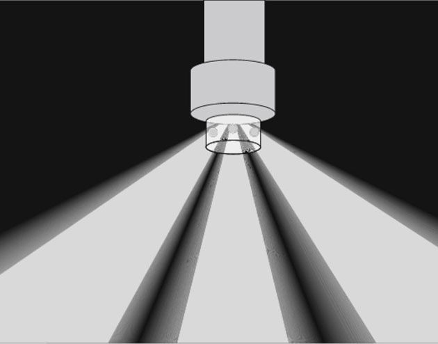
Source: Wise Global Training
Water mist also has the effect of partially scrubbing the air of toxic by-products caused by the fire.
Examples of equipment-specific types of fire protection systems and their functions
Floating roof tanks
Storage tanks with floating roofs have the potential to leak vapour from the rim seal. If that happens and the vapour ignites and it is not dealt with immediately, it can result in an escalation of events and a potential catastrophic outcome.
Consequently, a constant monitoring and protection system is needed so that any fire is detected and dealt with automatically and immediately. One solution is to place a linear heat detection system at the rim seal area of the roof and connect this to a number of foam based fire extinguishing modules positioned around the perimeter of the roof, as shown in Figures 8 and 9.
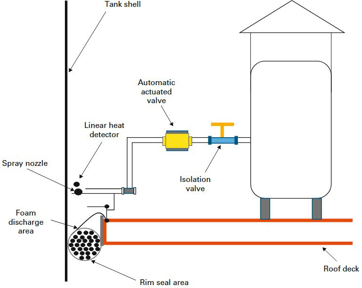
Source: Wise Global Training
When the linear heat detector registers a fire, as well as raising the alarm, it will also activate the fire extinguisher module nearest to the fire. This will then flood the immediate area with foam and extinguish the fire.

Source: Wise Global Training
An alternative to individual foam based fire extinguishing modules positioned around the perimeter of the roof is to have a number of foam outlets positioned around the top wall of the tank, as shown in Figure 10.

Source: Tal Glazer
These are connected by pipework to a foam mixing tank positioned outside the bunded area. This mixes and pumps the foam through the pipes to the outlets where it is discharged to flood the perimeter of the tank.
The foam can be supplemented by the fire service if required as the mixing tank will have a foam inlet for the emergency service to add additional foam.
Additionally, external fixed water spray systems may be fitted. Figure 11 shows such a system in operation.
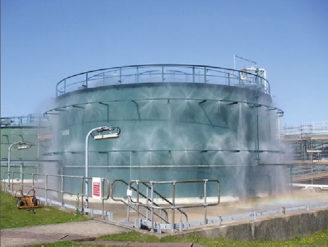
Source: Martin Wall – Shutterstock
As well as fighting fires, this kind of system can offer a cooling effect if required.
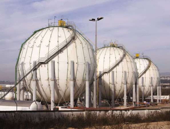
Fire protection systems for spherical storage tanks
Fire protection systems for spherical storage tanks generally employ a water based fire protection system. are a number of systems, each with their own advantages and limitations. These are:
- Water deluge systems;
- Fixed monitor systems;
- Water spray systems.
We shall now look at the merits of each of these systems in turn.
Fire protection systems for spherical storage tanks – water deluge system
A water deluge system for spherical storage tanks
works on the principle of having a single or a number of outlets placed on the top of the vessel. When these are activated by an alarm which has sensed a fire, water pours from these outlets and runs down over the surface of the vessel, potentially extinguishing the fire.

Source: Dreamstime
The advantages of the system are that it is quick to respond to any alarm trigger, it is generally automatic and, because the outlets are large, it is less prone to plugging.
Source: iStock
The disadvantages of the system are that there are areas where the deluge might not prove adequate, such as leg structures, and that this type of system is not as effective against jet fires as other, more direct systems.
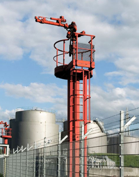
Fire protection systems for spherical storage tanks – fixed monitor system
A fixed monitor system for spherical storage tanks is where vessels are surrounded by ground based water hydrants. These either have monitors affixed to them, or monitors are positioned independently around the vessel so that a visual impression is available to the control room at all times.
Source: iStock.
When a fire is detected, the alarm is raised and the hydrants are either automatically operated by the system or manually operated by personnel. The hydrants can be fitted with an oscillating facility which sprays the water from side to side. This allows the water to be directed over a wide area without the need for an operator to be present.
The main disadvantage is that if operators have to manually operate the hydrants, this places them dangerously close to the fire. Another factor is that the strength and direction of any wind may have an effect on the water being directed onto the sphere.
Fire protection systems for spherical storage tanks – water spray system
A water spray system for spherical storage tanks is made up of a network of water pipes which totally surround the vessel. These have spray nozzles fitted to them at regular intervals which point inwards towards the vessel. When these are activated by an alarm which has sensed a fire, water is sprayed from these nozzles onto the entire surface of the vessel with the aim of extinguishing the fire.
The advantages of this system are that it is quick to respond to any alarm trigger, it is generally automatic, and the whole surface of the vessel gets a good dousing.
The disadvantages are that if the vessel experiences a vapour cloud explosion, the system is susceptible to damage and the nozzles, which have small outlets, are prone to plugging. Also, this type of system is not as effective on jet fires as other, more direct systems.
Gas turbine systems and compressor systems
Gas turbines and other major driven equipment, such as compressors and pumps, are widely used in the oil and gas industry, especially offshore, for a variety of functions.
These include:
- generating electricity,
- air compression,
- pumping, etc.
These items of machinery, particularly gas turbine units, are complex items which operate at high speeds and high temperatures.
A complete gas turbine system is made up of a number of separate areas or compartments. These include the turbine compartment, the generator compartment, the fuel pump compartment, the lubricating skid and the electrical control room, all of which will require individual fire protection systems.
However, the major fire hazard is associated with the turbine compartment, where there is the potential for fuel or lubricating oil to leak and come into contact with surfaces of the turbine, which operate at temperatures well above the auto-ignition temperature of the fuel and oil. If either the fuel or the lubricating oil leaks and comes into contact with one of these hot surfaces, it will cause a fire.
Historically, these types of fire have been dealt with using inert gas systems such as carbon dioxide. However, the effectiveness of these systems is dependent on having an atmospherically secure area so the gas cannot escape, which has proved a problem in the past. One study on gas turbine fires concluded that 37 % of fires tackled by inert gas systems failed because the gaseous agent had leaked from protected enclosures through open doors or ventilation.
The present consensus is that water mist systems are the most appropriate means of dealing with a fire in the turbine compartment. However, the main concern lies with ensuring that if the system is activated, it does not cause thermal shock on the turbine casing. This is achieved by strategic positioning of the mist nozzles in a location where they will not directly spray the surface but create a mist cloud which envelopes and cools these hot surfaces by heat transfer, turning the water droplets to steam.
REVISION QUESTIONS FOR ELEMENT 4
- Describe how an infra-red gas detector system works;
- Explain what passive fire protection is;
- With regard to passive fire protection, explain the difference between a wall coded as H120 and a wall coded as A30;
- Foam has a number of different effects on a fire. Give THREE of these effects and explain how each of them affects a fire;
- Describe an appropriate fire protection system that could be used on a floating roof storage tank.
Answer 1
Infrared absorption combustible gas detectors work by being able to recognize the specific absorption characteristics that hydrocarbon molecules have to infrared light. They send an infrared beam between a fixed transmission device and a fixed receiving device. The more hydrocarbon molecules that are present in a given space being monitored by these devices, the higher the absorption of infrared radiation which is detected by the receiving device.
Answer 2
The term “passive fire protection” covers the materials, products and design measures built into a building or structure in order that any fire which may start in the building or structure is restricted in its growth and spread. This is achieved by controlling the flammability of the structure, including walls, ceilings, floors, doors, etc., as well as by protecting structural steel members from severe heat which might compromise their integrity. Finally, the building or structure is designed in a way that divides it into separate fire containing compartments. This is so that any fire which may start will be restricted, or contained within a limited area.
Answer 3
Walls and divisions which have been manufactured as passive fire protection are coded in relation to the type of fire they are designed to withstand and its duration. The code is made up of a letter (either H or A) followed by a number (0, 30, 60 or 120). The letter indicates what type of fire the wall or division has been made to withstand. “H” type fire walls are manufactured to a standard that will withstand hydrocarbon fires. Whereas “A” type fire walls are manufactured to a standard that will only withstand cellulosic fires. The number which follows the letter indicates the length of time the wall or division has been designed to hold back the fire. For example, a wall with a “H120” coding is designed to withstand a hydrocarbon fire for 120 minutes, whilst a wall with an “A30” coding is designed to withstand a cellulosic fire for 30 minutes.
Answer 4
- A separating effect – The foam cover separates the combustion zone from the surrounding atmosphere and, as such, prevents oxygen feeding the fire.
- A covering effect – The foam cover stops evaporation of flammable vapours from the burning material. This means flammable vapours, which would normally be encouraged by the heat of the fire and which feed the fire, are stopped at source.
- A cooling effect – When foam is applied to a fire which is fed from a liquid source of fuel, water is gradually discharged by the foam which adds a cooling effect to the flame.
- A suppression effect – High- or medium-expansion foam used to flood areas will suppress the release of flammable vapours/gases and so prevent them combining with air which is necessary for the combustion process to take place.
- An insulating effect – Foam has a low thermal conductivity level. Consequently, when foam covers any flammable liquid which is not burning, it tends to insulate it from thermal radiation and ignition.
- A film formation effect (AFFF – aqueous film forming foam) – Foam which is used on non- polar hydrocarbons (the majority of hydrocarbons) produces a thin aqueous film which helps the foam flow, as well as assisting in the extinguishing process and inhibiting re-ignition.
Answer 5
System (a)
Floating roof storage tanks have a linear heat detection system at the rim seal area of the roof and this will be connected to a number of foam based fire extinguishing modules positioned around the perimeter of the roof. When the linear heat detector registers a fire, as well as raising the alarm it will also activate the fire extinguisher module nearest to the fire. This will then flood the immediate area with foam and extinguish the fire.
System (b)
Floating roof storage tanks have a linear heat detection system at the rim seal area of the roof, and this will be connected to a fire extinguishing system which has a number of foam outlets positioned around the top wall of the tank. These are connected by pipework to a foam mixing tank positioned outside the bunded area. This mixes and pumps the foam through the pipes to the outlets where the foam is discharged to flood the full perimeter of the tank. The foam can be supplemented by the fire service, if required, as the mixing tank will have a foam inlet for the emergency service to add additional foam.