The increase in size of Liquid Gas Carriers led to the development of fully refrigerated LPG ships which carry their cargoes at about atmospheric pressure.
- General description
- Addendum
- Cargo Tanks
- General operating principles
- Loading
- Refrigerating the Cargo on Passage
- Discharging
- Gas-freeing
- To Gas-up the Tanks after They have been Gas-freed, Prior to Loading
- To Cool Down the Tanks Prior to Loading after Gas-freeing
- Summary of gas-freeing and gassing-up
- To gas-up with the vapour as indicated
- Cargo handling equipment
- Reliquifaction Systems
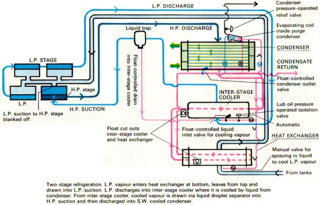
- Two-stage Refrigeration
- Seawater Cooled Condensers
- The Inter-stage Cooler
- The Heat Exchanger
- Cascade System of Refrigeration
- The R.22 Compressors
- R.22 Condensers
- The R.22 Receivers
- Filter and Liquid Trap
- The Cargo Compressors
- The Cargo Condensers
- Methanol Injection System
- Vaporisers
- Type “A”
- Type “B”
- Air Dryer
- Gas/Air Heater
- Cargo Heaters
- Type “A”
- Type “B”
- Submerged Cargo Pumps
- Emergency Cargo Pump
- Deck Storage Tanks
- Cargo operating procedure
- Loading
- Completing Loading
- To Refrigerate the Cargo on Passage
- Two-stage Reliquifaction
- Points to Watch Whilst the Plant is Running
- Cascade System of Reliquifaction
- To Start the Compressors
- Points to Watch Whilst the Plant is Running
- To Shut Down the System
- Other Points to Watch
- Discharging
- To Gas-free the Vessel
- Puddle Heating
- To Estimate the Time it Will Take for Puddle Heating
- Tank Warming
- Inerting the Cargo Tanks
- Flushing Through with Air
- Preparing the tanks to receive cargo after they have been gas-freed
- Procedure when changing grades and types of cargo
General description
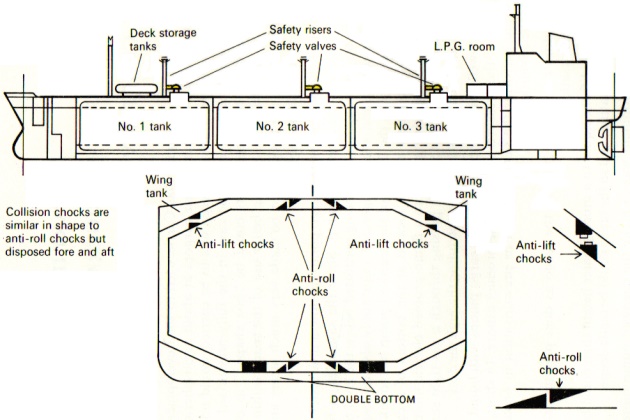
Because the tanks in which the cargo was to be carried would no longer be subject to high pressures, as is the case in the fully-pressurised and semi-refrigerated ships, the cargo tanks could be “box shaped” as opposed to spherical or cylindrical, so making better use of the space within the ship’s hull. Additionally, the tanks could be made very much larger and, for any given size, much lighter. See Fig. 1.
To deliver the product to the cargo pump suction, a new system had to be designed. This was the deepwell pump. Since the same design restrictions relating to no joints, glands, etc., being permitted below the level of the deck in fully-pressurised and semi-refrigerated ships apply also to vessels of the fully-refrigerated type, the design of the deepwell pump has to take this into consideration. The pump itself is located at the bottom of a cargo tank, connected by a long driving shaft to a flame-proofed electric motor situated on top of the cargo tank, the shaft passing through a gas-tight seal where it penetrates the tank dome, the dome protruding through the deck.
The deepwell pump supplies the main cargo pumps with liquid, and these pumps boost the pressure, and send the product ashore. In short, the deep-well pump performs the same function as pressurisation in pressure ships, but has the advantages that:
- it does not tend to heat up the cargo as does pressurisation due to condensation;
- it could lift the liquid to a much greater height than could be achieved by pressurisation, and so the tanks could be made deeper.
A natural development was to make the deepwell pump more powerful (multi-stage) with a discharge pressure of between 9 and 10 bars as opposed to about 2, and so obviate the necessity of always having to use the booster pump on deck. As the tanks became even deeper, the length of the driving shaft of the deepwell pump imposed certain limitations, and the submerged cargo pump was developed with the electric motor inside the cargo tank, thus dispensing with the long driving shaft.
A typical fully-refrigerated gas carrying vessel would have three or four main cargo tanks, each constructed with a trunk space and a protruding dome through which pass all the pipes, driving shafts, tank measuring devices, pressure gauge connections, etc. Each tank is fitted with a number of transverse wash plates which give added strength to the tank, and also cut down the surge effect of the product when the vessel is pitching, and also a longitudinal bulkhead which divides each tank in two so that each tank becomes a pair of tanks (port and starboard), but with a common vapour space at the top.
Each pair of tanks is fitted into a separate hold, or containment space, as the holds are called. The tank support system is designed so that the tanks may move to a limited extent to allow for the slight hogging and sagging movements of the hull when the vessel is in a seaway, and also to allow the cargo tanks to expand and contract according to the temperature of the product carried. These supports themselves are placed on solid floors and keelsons. Anti-roll chocks, anti-collision chocks and anti-lift chocks are also fitted.
Read also: Cargo Containment Systems of LPG and LNG
As an added safety measure, the spaces surrounding the cargo tanks in the containment space are inerted so that, unless the hull is pierced, there is no risk of a fire or explosion in the containment space even if, due to a leak from the cargo tank, gas collected in this space.
All the cargo pipe lines and cargo tanks must be constructed of special steel (“Arctic D”), capable of withstanding low temperatures, as well as that part of the Questions and answers to Crew Evaluation System Test about Ship Structure Conditionship’s structure surrounding the cargo tanks (virtually all the sides of the containment spaces), forming a secondary barrier to contain the cargo in the event of one of the cargo tanks being ruptured. Additionally, a means of emptying the containment spaces of any liquid product which has leaked in is provided.
In order to fulfil her role as a liquid gas carrier, the vessel must be capable of loading, carrying, discharging the cargo, and being gas-freed, either for dry-dock or to change the type of product to be carried. The cargo-handling system therefore comprises:
For Loading—A large diameter pipe leading from the main liquid line on deck to the bottom of each tank through which the liquid gas is loaded.
For Cooling the Cargo on Passage—A large refrigerating plant. In this connection, there are two methods of reliquifaction—two-stage and cascade. These systems are described separately, later. The reliquifaction plant is also used whilst loading, to relieve the build-up in pressure caused by the incoming liquid reducing the vapour space above the liquid level, thus compressing the vapour trapped in the space above the liquid.
For Discharging—A deepwell pump in each tank (one each side of the dividing bulkhead) to feed the booster pumps on deck, unless the deepwell pump is of sufficient power to dispense with the use of booster pumps.
For Gas-freeing the Ship:
- a puddle heating grid system in the bottom of each tank to evaporate the residual liquid remaining after discharge;
- an inert gas system for inerting the cargo tanks so that the vapour remaining in the cargo tanks after all the liquid has been evaporated can be displaced with inert gas with complete safety;
- a means of ventilating the cargo tanks with air to remove the final traces of vapour after the tanks have been inerted, and to make the tanks ready for entry, if required. (The inert gas system is also used for displacing the air with inert gas prior to loading.) Some ships are also provided with a system whereby the vessel’s cargo tanks may be filled with vapour whilst at sea. On deck there are separate liquid gas storage tanks of sufficient capacity that the liquid, when vaporised in a vaporising unit, can completely fill the ship’s cargo tanks with a vapour compatible with the succeeding cargo.
The ships are usually provided with a cargo heater to enable the vessel to discharge into pressure storage ashore, and a booster pump if the discharge pressure is significantly above 9 bars.
Some ships are provided with a separate purge line system at the top and bottom of each tank. The purge lines form a grid with tiny holes in the pipes and are used to diffuse the inert gas evenly at the top of the cargo tank, and to collect the exuding vapour from the bottom of the tank, so eliminating the many pockets of vapour which would otherwise exist if the liquid and vapour lines alone were used for this purpose.
Addendum
Cargo Tanks
These are built of special low temperature steel (“Arctic D”). They may be built in various shapes (prismatic) to make maximum use of the space available in the containment space into which they are fitted, but are so constructed as to minimise the free surface effect by having a small surface area at the top. This usually, but not always, takes the form of a trunk space.
Each cargo tank is divided into two by a longitudinal bulkhead to further reduce the free surface effect, and is strengthened transversely by a number of wash plates, which also reduce the surge effects of the liquid in the tank when the vessel is at sea. At the bottom of the longitudinal bulkhead is a bulkhead valve which, when opened, enables the tank to be pumped out, using one pump only.
At the top of the tank is the tank dome which is the only part of the cargo tank which protrudes through the deck, to which the access hatch lids are attached, and through this dome pass all the pipe lines, etc.
The after-end of the cargo tank is usually provided with a pump well into which the cargo pumps are fitted.
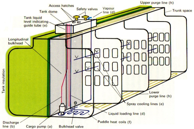
Each cargo tank is provided with the following equipment (See Fig. 2):
- Two cargo pumps (one either side of the longitudinal bulkhead) at the after-end of the tank in the pump wells, discharging through;
- The liquid discharge line which emerges through the tank dome and is connected to the main liquid line;
- An emergency pump trunk way into which an emergency cargo pump can be inserted in the event of both main cargo pumps failing;
- A liquid loading line connected to the main liquid line on deck and leading to the bottom of the cargo tank through which the product is loaded;
- A series of spray lines connected to the condensate line used for tank cooling purposes;
- A puddle heat grid system at the bottom after-end of the tank, used to evaporate the residual liquid when gas-freeing or changing grades;
- Two tank liquid level-indicating devices (one on either side of the longitudinal bulkhead). These usually consist of a float attached to a self-winding tape which moves up and down, either on guide wires or inside a guide tube, the liquid level being read off the tape through a gas-tight window at the top of and outside the tank;
- Two sets of purge lines (upper and lower) which form grids at the very top and the very bottom of the tanks. These purge lines have very small holes in them and are used to distribute evenly the inert gas or vapour fed into the tank and to collect evenly the displaced inert gas or vapour when gas-freeing or gassing-up the cargo tanks;
- A vapour line connected to the tank dome and through which vapour can be withdrawn by the compressors;
- A series of sample tubes for sampling the vapour when gas-freeing.
The cargo tanks are fitted with the following safety devices:
- At least two safety valves to relieve automatically any excess pressure in the cargo tank;
- High- and low-level alarms which give warning when the tank is nearly full when loading and nearly empty when discharging. They are operated by the liquid level-indicating device and emit alarm signals at soundings corresponding to 96 and 97 per cent. capacity when loading and at about 1 metre and 0,5 metre from empty when discharging. These alarms can usually only be silenced in the vicinity of the tank domes, so summoning the operators to their station if not already there;
- Overfill alarms. These are usually set at a depth corresponding to 98,5 per cent. capacity and, when actuated, usually shut the main loading valve and sound an alarm.
Externally, the tank is covered with insulation (although an internal form of insulation has been developed). Underneath the insulation are fitted the temperature recording probes. These are usually of the resistance type, relying on the variation in the value of their resistance caused by changes in temperature. They are powered by electric current of very low voltage and register on a temperature recorder located in a cargo monitoring room.
General operating principles
Loading
The vessel usually arrives alongside at her loading berth with her reliquifaction plant running, and with her cargo tanks cooled down to the required temperature, her liquid lines through which the cargo is to be loaded pre-cooled, and the pressure in her cargo tanks low (about 0,02 bar). Loading is effected through the liquid line into the bottom of her cargo tanks.
If a shore vapour return line is provided, it is important to ascertain the conditions under which it is used. If the returned vapour is flared, the vapour return line should be used as sparingly as possible, and only then to relieve excessive pressures (usually towards the end of loading) with which the reliquifaction plant is unable to cope. The running of the plant whilst loading is recommended because it serves to conserve product. In any case, it must be restarted when loading is completed and kept running during passage.
The maximum safe loading rate varies from ship to ship. but is usually in the region of 500 cubic metres per hour for each valve open. As the loading valves are shut when each tank is tilled to its correct level, the loading rate should be reduced accordingly.
Refrigerating the Cargo on Passage
In this operation, vapour is withdrawn from the top of the tanks to be refrigerated, compressed, condensed into a liquid in the condenser, and the condensed liquid returned to the tanks. The withdrawal of the vapour reduces the vapour pressure in the tank to below its saturated vapour pressure so that the liquid in the tank boils, latent heat given up and the tank therefore cooled.
However, there are two types of reliquifaction systems, namely two-stage and the cascade systems.
In the two-stage system the condenser is cooled with seawater. It requires a two-stage compressor to raise the pressure from about atmospheric pressure to about 15 bars. suitable for use with a seawater-cooled condenser.
A typical two-stage compressor is one with 8 pistons of which 6 are used in the first (LP) stage and 2 in the second (HP) stage. The vapour withdrawn from the tanks is sucked through a heat exchanger, which also acts as a liquid trap to the LP suction of the compressor from which it is discharged into the inter-stage cooler, where it is cooled by injecting liquid taken from the condenser, into the LP discharge pipe just before it enters the interstage cooler, reducing its temperature from about 70° to 30 °C. From the inter-stage cooler, the cooled vapour is drawn into the second-stage (HP) suction and then discharged into the seawater-cooled condenser, where it condenses. The relatively warm condensate first passes through the inter-cooler and then into the heat exchanger before it escapes through a float-controlled valve back into the cargo tank via the condensate line. As soon as the condensate passes through the control valve, it experiences a drop in pressure from about 15 bars (condenser pressure) to about 0.5 bar. This sudden drop in pressure causes a proportion of the condensate to evaporate and, in so doing, the condensate cools itself down to approximately tank temperature, and a mixture of cold condensate and vapour is returned to the tank.
If the condensate line were badly insulated, more of the condensate would evaporate to compensate for the temperature gained through the badly insulated line, until, if the line were so badly insulated that all the condensate were evaporated, the resulting cooling effect on the tank would be nil. The net cooling effect upon the tank being cooled is the latent heat of vapour withdrawn minus the latent heat of the vapour returned (or the latent heat of the liquid returned).
The cascade system of reliquifaction is shown in Fig. 3. In this system, a refrigeration unit using Freon 22 (R.22) discharges into a seawater-cooled condenser which condenses the Freon 22 into a liquid which passes from the condenser into a Freon 22 tank where it is stored. Liquid Freon 22 passes from the storage tank as required into the cargo condenser where a thermostatically controlled expansion valve allows it to evaporate inside a series of tubes in the cargo condenser, so cooling it. The evaporated R.22 goes back to the suction of the R.22 compressor where the cycle is repeated.
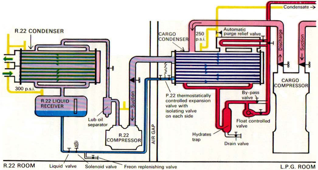
A large slow-revving single-stage cargo compressor withdraws cargo vapour from the cargo tank and discharges it into the Freon-cooled condenser. The sensible heat and latent heat of condensation of the cargo vapour heats up the cargo condenser, but as soon as this happens the thermostatically controlled expansion valve admits more liquid Freon, which evaporates in the cargo condenser tubes, keeps the condenser cool and, in so doing, removes the heat gained in the reliquifaction process.
To summarise, the Freon system removes heat from the cargo system, and the seawater passing through the R.22 condenser removes this heat into the sea.
The great advantage of the cascade system of reliquifaction is that the same refrigerant is used for all cargoes, which means that a plant can be designed where the only variable factor is the temperature of the seawater coolant, and because the maximum temperature of the seawater likely to be encountered in service can be easily ascertained, it is not too difficult to design a plant capable of working within these conditions. The plant is usually designed to work with a maximum temperature of the cooling water of 35 °C. (95 °F.), and it is very unlikely that warmer cooling water will be met in service.
Additionally, when more advanced types of ships are brought into service to carry products whose critical temperatures are below that of seawater (methane -83 °C., ethane +32 °C. and ethylene +9 °C.), the cascade, or even double cascade, system is the only method available.
When refrigerating cargo, it is usual to refrigerate all tanks simultaneously, but if the condensate were returned to all the tanks, some-might receive more than others. Accordingly, it is usual to return all the condensate to one tank at a time for a fixed period and then to change tanks, but allowance must be made for the number of reliquifaction units in service to ensure that equal quantities of condensate are returned, and the tanks not over-filled.
Discharging
Before the discharge commences, the liquid lines on deck must first be cooled down. This can be effected prior to arrival at the discharge berth during the course of refrigeration by returning the cold condensate to the tanks via the liquid line on deck and down through the loading line. (A cross connection between the condensate line and the liquid line is usually provided for this purpose.) However, it should be remembered that because the liquid line is of much larger diameter than the condensate line, the quantity of liquid in the line is very much larger, so the rate of flow is much slower. Due to the extra time spent in the line on deck, the heat gain is greater so, in general, it is more efficient to use the condensate line for refrigerating purposes. The liquid line is only used for condensate return purposes in order to pre-cool that line.
The method of starting the discharge varies slightly with the type of deepwell pump provided. If it is one with a low discharge pressure combined with a booster pump, then the best method to start the discharge is first to flush out any vapour in the liquid line on deck by using a deepwell pump to transfer a small quantity of liquid from one tank into another, so completely filling the liquid line on deck with cold product. By shutting the loading valve of the tank into which the cargo is being transferred, the full weight of the deepwell pump discharge pressure is thrown onto the suction of the booster pump. The booster pump can then be quickly purged of any remaining pockets of vapour and, as soon as it is primed with liquid, the booster pump can be started and the liquid cargo sent ashore.
With the more powerful deepwell pumps or submerged pumps, it is usual to start the discharge by opening the pump discharge valve about a quarter (about two turns) and then start the pump. Many of these powerful pumps need to operate against a back pressure to avoid cavitating, and the discharge valve is regulated to retain the required back pressure on the pump. Additionally, as the current consumption is related to the Questions and answers to Crew Evaluation System Test about Pumps and Pumping Operationspumping rate, before opening the manifold discharge valve, it is usual to circulate the cargo by opening the loading valve slightly and closing it as soon as the liquid discharge valve on the cargo manifold is opened and the product sent ashore.
Once the first tank is being discharged, the remainder of the pumps may be started so that all tanks are being discharged simultaneously.
During the discharge, due to the level of liquid in the tanks falling, the vapour spaces become enlarged. If the rate of evaporation of the product within the tank does not keep pace with the rate of discharge, the pressure in the tanks, which is bound to fall anyway, may come close to creating a slight vacuum. In this case, the pressure can be restored by using the ship’s vaporiser.
When it is particularly important to discharge the maximum quantity possible (e.g. if the tanks have to be gas-freed subsequent to discharge) the tanks should have the pressure restored prior to draining. The slight degree of undersaturation due to a fall in the tank pressure will cause the cargo pumps to gas-up sooner than would be the case if the pressure were restored.
Towards the end of discharge, when the liquid level in the tanks gets low, the pumping rate must be slowed by shutting in the pump discharge valve, so maintaining the back-pressure. In this way, the tanks can usually be pumped down to a level of about 20 centimetres. The liquid and vapour remaining after discharge is retained on board and used to keep the tanks cold for the next cargo.
Gas-freeing
After ensuring that the condenser is empty of all liquid, the first step is to vaporise the liquid still remaining in the cargo tanks after discharge. This is done by puddle heating. To do this, vapour is withdrawn from the top of the tanks by the compressors and discharged into the puddle heat coils at the bottom of the tanks, and therefore immersed in the residual liquid. The vapour discharged into the coils condenses into a liquid, and the latent heat of condensation warms the surrounding liquid causing it to boil and replace the vapour which has been withdrawn, so that the pressure in the tanks remains fairly constant. Being under the discharge pressure of the compressors, the vapour inside the puddle heat coils condenses readily because, being under pressure, the temperature at which it condenses is much higher than the surrounding liquid. To take a practical example, propane at 3 bars pressure will condense at about —5 °C., whereas the temperature of the surrounding liquid propane will be at about — 40 °C.
The condensed liquid in the puddle heat coils is driven by the pressure from the compressors up the puddle heat return line into the condensate line, where it can be discharged:
- into the deck storage tanks, if space is available, for use when gassing-up the tanks on a future occasion;
- into another tank, if only one tank is to be gas-freed (e.g. to overhaul a deepwell pump);
- over the side, using a flexible hose.
After all the liquid in the tanks has been evaporated, the tanks are warmed by circulating with vapour, using the compressors, sucking from the top of the cargo tanks and discharging, through the gas-heater, if provided, into the bottom of the tanks, thus evaporating any final trace of liquid after puddle heating and warming the tank. It is very important, particularly when gas-freeing with air after an ammonia cargo, to be thorough, and warm the tanks to near ambient. Ammonia has the characteristic of being very persistent, and if the tank-warming operation is curtailed in order to save time and air ventilation started earlier, the whole operation can be ruined. It is thought that a very thin layer of colder ammonia vapour prevents the warmer vapour from vaporising the liquid. If, say at 0 °C. it is decided to start ventilating with air, the air breaks through this cold layer of vapour and the residual liquid starts to evaporate and the temperature falls rapidly to an alarmingly low level. Water vapour in the air condenses and forms an aqueous solution with the ammonia and the operation can be prolonged by anything from a week to ten days.
With the cargo tanks warmed to near ambient temperature, the pressure in the tank is reduced to atmospheric pressure by releasing any excess pressure up the mast.
The next stage depends upon the product previously carried. If LPG, the vapour must be displaced by inert gas. If the product was ammonia, the ammonia vapour may be displaced by air. In the case of displacing LPG vapour, inert gas is taken from the inert gas generator and forced under pressure into the top of the tank, displacing the heavier LPG vapour from the bottom. The appropriate purge lines will be used, if provided, or the vapour and liquid lines, if they are not. In some ships, it is possible to inert the cargo tanks and displace the LPG vapour in series, the displacing inert gas pushing the LPG vapour from the bottom of one tank into the top of the next. If the ship’s lines do not permit this, then the inerting process is done one tank at a time, and sufficient gas introduced into each tank to displace the tank’s complete volume. After the tanks have been inerted, the gas-freeing process is completed by flushing through with air until the vessel is completely gas-free.
In the case of gas-freeing after ammonia, the inerting process can be omitted, and the tanks flushed through with air but, ammonia being lighter than air, the air is introduced into the bottom of the cargo tanks, displacing the ammonia through the top. Ventilating with the compressors or blowers is continued until the concentration of ammonia is reduced to an acceptable level (about 700 p.p.m.) when the tank lids are removed and the ventilation supplemented with air-driven fans which, in conjunction with a chute, deliver large quantities of air to the bottom of the tanks, the ammonia vapour welling out through the open hatchway. This greatly increases the rate of dispersal of the final traces of ammonia, the concentration of which should be reduced to below 20 p.p.m. if the next cargo to be loaded is LPG.
To Gas-up the Tanks after They have been Gas-freed, Prior to Loading
If the next cargo to be loaded is LPG, the tanks must be inerted before the tanks are gassed-up. The procedure for this is the same as for displacing the propane vapour with inert gas but only 70 per cent. by volume need be passed into each tank. If this method is used, the atmosphere within each tank is thoroughly mixed so that the resulting concentration of oxygen in the tank is 8 per cent. or below. (It takes a minimum of 10 per cent. of oxygen in air to sustain combustion, and so long as the oxygen content is below this, no combustion can take place.)
The inert gas can then be displaced by LPG vapour, the vapour being introduced into the bottom of the tank and the inert gas displaced through the top. Inert gas, being lighter than LPG vapour, will form a layer above the vapour so that there is little admixture of the two.
If the next cargo to be loaded is ammonia, the tanks need not be inerted, but ammonia vapour being lighter than air is introduced at the top of the tank, displacing the air from the bottom.
If deck storage tanks containing sufficient liquid product for the purpose of gassing-up the ship are fitted, there is no problem because the liquid can be vaporised in the ship’s vaporiser and directed as required into the cargo tanks whilst the ship is at sea.
If no such tanks are fitted, the process of gassing-up and cooling down must be carried out alongside at the loading terminal. If a vapour return line is provided, vapour (if available) or liquid which can be vaporised in the vaporiser, is taken from shore, and the tanks gassed-up, returning the vapour/inert gas mixture to the shore where it will be flared. If, no vapour return line is provided, then it is quite safe to release the inert gas/vapour mixture up the mast, as is done at sea, but not all terminals will agree to this. If they will not agree, then one or more tanks can be used as buffer tanks, and one tank gassed-up with vapour. The gas/air mixture from the tank being gassed-up is conducted to the bottom of the buffer tank/s where, due to stratification effect, inert gas being lighter than LPG vapour will form a layer above the LPG vapour so that there is very little mixture of the two and practically pure inert gas is released into the atmosphere from the buffer tank. In this way one tank can be completely filled with vapour.
Finally, if the terminal authorities are adamant that nothing may be released to the atmosphere, then the only remaining way is to arrive alongside with the tanks inerted but under no pressure. The smallest tank is then selected for gassing-up, and vapour is taken into this tank so that the pressure rises to a level below the safety valve setting. The inert gas on top of the LPG vapour is then transferred to the other tanks, using the compressors until the pressure in the tank being gassed-up is down to zero. The operation is then repeated, taking more vapour into the first tank and then transferring it to the others. In this way, it is hoped that one tank can be gassed-up sufficiently for the reliquifaction plant to start cooling down and sufficient liquid taken for the ship to proceed to sea and gas-up the remaining tanks.
The procedure for gassing-up with ammonia is the same, except that the ammonia vapour is introduced into the tops of the tanks instead of the bottoms, and the pressure relieved from the bottoms of the tanks.
To Cool Down the Tanks Prior to Loading after Gas-freeing
If the ship’s tanks have been gassed-up at sea, there will be no liquid in the tanks. Cooling down is effected by using the Questions and answers to Crew Evaluation System Test about Basic Refrigeration Theoryrefrigeration process. If the ship is alongside, then liquid can be taken from shore and sprayed into the tanks. The liquid droplets sprayed into the tanks will at once vaporise, thus cooling them; but the increase in the amount of vapour in the tanks will cause a rise in the tank pressure. This increase in pressure can be relieved by reliquifaction or by allowing the vapour to return ashore via the vapour return line; but if to do this would involve flaring, such a procedure can be wasteful of product.
In short, the quickest way to cool down is to spray liquid into the tanks and return the excess pressure ashore via the vapour return line. The most economical way (from a conservation of product point of view) is to take sufficient liquid from shore, to maintain a reasonable pressure in the tanks and to relieve excess pressure by reliquifaction, taking extra liquid as the pressures in the tanks fall.
The cooling rate varies from ship to ship, but is usually in the region of 4 °C. per hour for fully-refrigerated ships.
When the presence of liquid is firmly established in the bottom of the tanks, loading in bulk through the liquid loading line may commence. When the tanks have been cooled at sea by refrigeration after gassing-up, it will still be necessary to spray liquid into the tanks until liquid is firmly established before loading through the main liquid loading line.
Summary of gas-freeing and gassing-up
To gas-up with the vapour as indicated
Cargo handling equipment
Reliquifaction Systems
In the two types of reliquifaction systems (two-stage and cascade), the deck house in which the machinery is housed is divided into two compartments by a gastight bulkhead (some have a double bulkhead containing an air gap). In the one compartment are located the electric motors, which drive the compressors in the other.
The motor room is kept pressurised and is usually provided with two doors forming an air lock for entry. The compressor room (or Properties and hazards of shipping LNG, LPGhazardous area) is kept ventilated but not pressurised.
Two-stage Refrigeration
In the motor room are housed:
- the electric motors which drive the compressors;
- the electrically driven pump for circulating hot water in the compressor sump-heating system;
- any other electrical plant (e.g. air blower driving motor, electrically heated sump-heater tank, etc.).
The plant used for two-stage reliquifaction and which is located in the compressor room comprises:
- a number of two-stage compressors;
- seawater-cooled condensers;
- the associated heat exchangers and inter-stage coolers;
- steam-heated tank for sump-heating.
The compressors used for two-stage reliquifaction are generally similar to those used in single-stage, but have been adapted for two-stage operation. They usually have cylinders in multiples of four (3 LP supplying 1 HP), i.e. 4,8 or 12 cylinders.
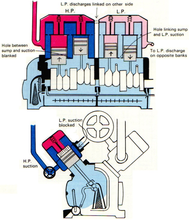
A typical 8-cylinder two-stage compressor would be generally similar to the Loire compressor described in Part I of this book, having a hollow cylinder block into which the cylinder sleeves are fitted, with suction and delivery plates concentrically arranged, the delivery plates being held in position with strong pins and dished washers.
How the compressor is made two-stage is shown by the adaptations to the 8-cylinder Loire compressor. The arrangement of the 8 cylinders is such as to form four separate 2-cylinder compressors, arranged in two banks in “V” formation, so that they are all driven by the same crankshaft. Three of these 2-cylinder compressors are used in the LP stage, the fourth in the HP stage. Each of these “2-cylinder compressors” has its own suction. The 3 LP compressors have their discharge galleries linked together to make a common discharge. The LP stage discharges through an inter-stage cooler where the vapour discharged from the LP stage is cooled, and is then drawn into the suction of the HP stage, which has its own separate discharge. The arrangement is shown schematically in Figs. 4 and 5. Because the suction pipes leading to the LP stage have the double function of supplying vapour, and generally speaking bracing the machine, superficially it would appear that the HP stage also has an LP suction, but this apparent LP suction to the HP stage is blocked off, and the HP unit draws its suction from a smaller inlet pipe.
Lubrication is similar to that of a single-stage compressor, and consists of a gear wheel pump sucking through a conical strainer and discharging through a filter and then a cooler into a distributing pipe which feeds the lubricating oil to the end and centre bearings and shaft seals, the lubricating oil passing through holes drilled in the crankshaft to lubricate the big and little end bearings. The cylinders themselves are splash-lubricated. Lubricating oil pressure is regulated in the same way as with the single-stage compressors by an externally adjustable spring-loaded ball relief valve.
The compressors are also fitted with a sump heater to drive off gases which would otherwise dissolve into the oil, thereby contaminating it. The compressor is also fitted with cylinder off-loading devices which off-load 4 cylinders at a time in the proportion 3 LP cylinders off-loaded for every 1 HP.
The compressors are fitted with the following safety devices:
- HP cut-out, set at 17 bars;
- LP cut-out, set at 10 bars;
- HP and LP high temperature cut-outs, both set at 120 °C.;
- lubricating oil differential pressure cut-out, set at 1.5 bars;
- a safety disc cut-out which replaces the older type bursting discs.
Other safety devices not fitted on the compressor itself but on associated equipment are float-operated cut-outs in the heat exchanger and inter-stage coolers to prevent liquid entering the compressors.
Each of the devices listed above stops the machine when actuated. In addition, the machines are fitted with a spring-loaded relief valve in the LP suction, operating when the differential pressure between the suction and discharge exceeds 12 bars, which, by connecting the suction to the discharge, causes the compressor to circulate. A similar relief valve in the HP suction operates if the differential pressure between suction and discharge exceeds 16 bars. When any of these circulating devices operates, causing the compressor to circulate, the compressor quickly stops itself on a high temperature cut-out.
Seawater Cooled Condensers
The cargo condensers used in two-stage refrigeration are very similar to those used in semi-refrigerated ships.
The main difference is that an automatic control, sensing condenser pressure, is fitted to the mast relief valve on the incondensible separator. A rise in condenser pressure (which indicates the presence of incondensibles) actuates the controller which causes the mast relief valve to open and release the incondensibles up the mast to the atmosphere.
Because the normal operating pressure of the condenser varies according to seawater cooling temperature and also with the type of product being reliquified, the relief setting on the controller can be varied, and is usually set at about 1 bar above the “normal” operating pressure of the condenser.
The Inter-stage Cooler
In a two-stage compressor, the discharge temperature of the first (LP) stage is so high that if the hot vapour were fed directly to the suction of the second (HP) stage, the HP discharge temperature would be excessive and the compressor would stop itself on the HP high temperature cut-out. Accordingly, the temperature of the LP discharge is reduced by spraying in a small quantity of liquid taken from the condenser, which quickly evaporates, uses up latent heat and so cools the vapour before it passes to the HP suction. To do this safely, the hot LP discharge vapour is fed into the inter-stage cooler. The liquid is sprayed into the LP discharge pipe just before it enters the cooler. The liquid injection is controlled by a float which, via a controller, operates a valve permitting sufficient liquid to enter the inter-stage cooler to maintain a low level of liquid. Should the level of the liquid rise due to a failure of the injection control system, a float switch will stop the compressor to prevent liquid entering the suction. The HP suction draws vapour from the top of the inter-stage cooler.
A liquid droplet trap is placed between the inter-stage cooler and the compressor HP suction to remove any entrained liquid droplets. Should any liquid collect in the trap, it will be drained back into the inter-stage cooler.
Should the compressor stop, the drop in lubricating oil pressure of the compressor operates a controller which closes a valve and shuts off the liquid being injected into the inter-stage cooler, thereby preventing the inter-stage cooler from being flooded with liquid.
The Heat Exchanger
The heat exchanger is situated immediately under the inter-stage cooler. Its main functions are:
- to act as a liquid droplet separator (liquid trap);
- to exchange sensible heat between the warm condensate coming from the condenser and the cold vapour coming from the tank being refrigerated, so that the condensate is cooled, and the cold vapour warmed and superheated.
The incoming vapour enters the heat exchanger at the bottom, and the compressor draws its vapour from the top of the heat exchanger. It sometimes happens that the incoming vapour is too warm. In that case, it is possible to cool it down by injecting a small quantity of liquid into the vapour line immediately before it enters the heat exchanger. This is done manually and there is no automatic control. The heat exchanger is provided with a gauge glass, and should any liquid form in the heat exchanger it can be drained away by a manual cock which drains the liquid into a cargo tank. Should an undue quantity of liquid collect in the heat exchanger unnoticed, a float-operated switch will stop the compressors to prevent liquid being drawn into the first stage of the compressor.
Cascade System of Refrigeration
The motor room, usually called the R.22 room, contains the whole of the Freon system equipment (motors, Freon compressors, Freon condensers and Freon storage tanks), in addition to the motors which drive the cargo compressors.
In detail, the equipment in the R.22 room comprises:
- 3 single-stage 8-cylinder “V” block compressors;
- 3 seawater-cooled condensers;
- 3 R.22 receivers, located underneath the condensers and gravity filled;
- 3 cargo compressor motors which drive the cargo compressors in the LPG room;
- 1 freshwater header tank feeding a heater tank;
- 2 electrically driven circulating pumps used for heating or cooling the crossheads and guides of the cargo compressors. A seawater-cooled heat exchanger is also fitted for cooling the water returns from the cargo compressor.
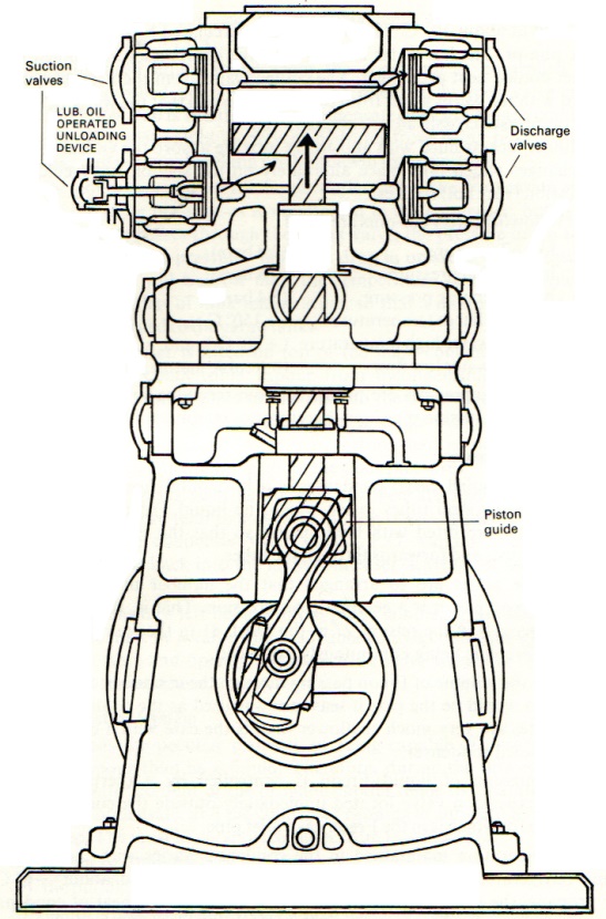
The R.22 Compressors
These work in a similar way to the compressors used in semi-refrigerated carriers.
They are usually fitted with oil-pressure operated unloading devices which unload the compressors by holding open the cylinder suction valves so that they can be operated at 25, 50, 75 and 100 per cent. capacity.
The following safety devices are fitted:
- Low oil-pressure cut-out (4.2 bars);
- High discharge pressure cut-out (17.7 bars);
- Low suction pressure cut-out (variable).
R.22 Condensers
These are conventional seawater-cooled condensers with a throughput of seawater capable of condensing R.22 when the seawater temperature is 35 °C., when its outlet temperature will be about 37 °C. and the pressure about 15.5 bars.
The R.22 Receivers
These are located underneath the R.22 condensers and are gravity filled. Each has a capacity of about 0.3 cubic metres and is fitted with a liquid level gauge. They are usually maintained at about half level.
The equipment in the LPG room comprises:
- filter and liquid trap in the main vapour line;
- slow-revving single-stage double-acting cargo compressors;
- Freon (R.22) cooled condensers;
- methanol injection pump.
Filter and Liquid Trap
This is located where the vapour lines coming from the cargo tanks enter the room from the deck. It is fitted with a float-operated switch which stops the compressors if it is actuated by liquid accumulating in the trap, thus protecting the compressors from liquid entering the compressors.
The Cargo Compressors
In double-acting compressors, both ends of each cylinder are used alternately for suction and discharge. The cylinders are separated from the sump by an entablature with gas-tight glands at the top and bottom through which the piston rod can move up and down when the compressor is running. However, as it is possible for small quantities of gas to leak past the glands, particularly on the compression stroke, the entablature is linked by pipe to the suction end of the compressor, and the sump to the entablature so that any build-up in pressure is avoided.
Lubrication is by means of a gear wheel pump driven by the crankshaft. The pump sucks through a strainer and discharges into the crankshaft where holes drilled in the crankshaft conduct the oil to the main bearings, the bottom end bearings and along the crankshaft to the shaft seal chamber. From the bottom end bearings, the oil passes up through the connecting rod to the top end bearings. The piston guide bearing is splash lubricated. The pistons at the top of the compressor are not lubricated, but have a minute clearance instead, and are therefore oil-free.
Associated with the lubricating oil system are the oil pressure-operated unloading devices, one fitted to each of the two lower suction valves. With this arrangement, the compressors can be run at 50 per cent, 75 per cent. and 100 per cent. capacity. The unloaders work in the following manner. A powerful spring acting on one side of a piston pushes a rod which holds open the suction valve so that on the compression stroke, instead of discharging through the discharge valve, it discharges through the suction valve, thereby unloading the cylinder. By operating a valve on the lubricating oil system, oil pressure acts on the other side of the piston, overcomes the spring, pushes back the piston and allows the suction valve to close, so placing the cylinder on load.
A cooling/heating system is fitted to prevent overheating of the compressor crossheads and guide bearings. The cooling water used for this purpose is freshwater stored in a header tank in the R.22 room, beneath which is a thermostatically controlled heater tank in which the water is maintained at about 50 °C. The freshwater is circulated by one of two small electric pumps. The hot water returns from the compressor are cooled by a seawater-cooled heat exchanger. The cooled water from the heat exchanger is mixed with the warm water from the heater tank so that the water delivered to the compressor crosshead is at about 35 °C.
Cylinder jackets filled with anti-freeze mixture absorb the violent temperature changes which take place alternately on the suction (very cold) and compression (very hot) strokes.
The following safety cut-outs are fitted:
- low oil pressure (2.8 bars);
- low suction pressure (0.8 bars);
- high discharge pressure (5.4 bars);
- high discharge temperature (+ 150 °C.);
- cooling water high temperature (+ 80 °C.); and
- cooling water low flow (0.6 cubic metres per hour).
The cargo compressors are protected from receiving solids by a strainer located inside the suction pipe, and therefore not readily visible externally.
The Cargo Condensers
The Freon-cooled cargo condenser is a horizontal steel drum through which pass many steel tubes inside which the liquid Freon is evaporated. The end plates are fitted with baffle plates so that the evaporating Freon passes backwards and forwards through the tubes.
The baffle plates are so arranged that the number of tubes through which the Freon passes is a geometric progression. That is, through 3 tubes in the first pass, 9 in the return, 27 in the third, 81 in the fourth and so on, so that the Freon is being continuously expanded.
Because the volume of Freon passing through the condenser is very much smaller than would be the case if seawater was used as the cooling medium, the end plates are very much shallower than is the case with a conventional seawater-cooled condenser.
The admission of liquid Freon is controlled by a thermostatically-controlled expansion valve located immediately outside the condenser, the sensing bulb for which is in the Freon gas outlet pipe.
The temperature maintained in the condenser varies with the product being refrigerated and is about +3 °C. for ammonia and about —6 °C. for propane, the difference being due to the greater latent heat of condensation for ammonia than propane (301.5 for ammonia compared with 90.4 for propane). The Freon gas return equivalents are about —5 °C. for ammonia and about — 15 °C. for propane.
The condensed liquid outlet from the condenser is controlled by a liquid-level controlled float valve. A hand operated by-pass valve is also fitted. A hydrates trap is situated in the condensate line between the condenser and the liquid outlet valves to prevent hydrates from being returned to the cargo tanks and perhaps blocking up the holes in the spray lines.
On the condenser side of the liquid outlet valve, the condensate will be subject to the same pressure as is maintained in the condenser, but as soon as the condensate passes through the outlet valve, the pressure drops to that of approximately tank pressure. With this drop in pressure, a small quantity of the condensate will boil-off until the temperature of the condensate is reduced to nearly that of tank temperature, so that a mixture of cold liquid and Vapour is returned to the cargo tank.
A purge condenser is fitted on top of the main condenser, its function being to separate condensible vapour from incondensible gases, and to release the incondensible gases up the mast to the atmosphere. This is done by leading the very cold condensate line through the purge condenser, thereby cooling it to a much lower temperature than is maintained in the main condenser, whilst remaining under the same pressure.
Incondensible gases such as air and nitrogen are lighter than LPG vapours and therefore tend to collect at the top of the condenser. They pass up into the purge condenser where any LPG vapour content readily condenses and runs back into the main condenser, leaving the incondensible gases behind.
The incondensibles left behind in the purge condenser are automatically released up the mast by a valve which is regulated by a controller which senses condenser pressure and opens the mast release valve whenever the pressure in the condenser rises above a pre-set level.
Methanol Injection System
Propane has the peculiar property of being capable of absorbing more water as a vapour than as a liquid. Therefore, during the process of liqui-faction, the water content of the propane vapour tends to separate out from the propane condensate, and the condenser running at sub-zero temperatures would ice up. The most likely spots to suffer from this effect are:
- the cargo condensers;
- the puddle heat coils.
Methanol is used as an anti-freeze and, if necessary, as a de-icing agent.
To prevent the icing up of the condenser during the process of liquifying the propane, a small electric-driven methanol pump draws methanol from a storage tank and discharges it into the cargo condensers where the compressor discharge pipe enters the condenser.
The methanol pump is a reciprocating pump running at constant speed, but its output can be varied by altering the length of each stroke of the pump by means of a variable eccentric. The control fitted allows the stroke (output) to be varied. It is usual to set the pump stroke to 15 per cent. at the commencement of refrigeration reducing to about 5 per cent. when the plant settles down.
Vaporisers
A vaporiser converts a liquid into a vapour with the use of steam heat. There are several types of vaporiser, of which two will be described.
Type “A”
In this type, many steel tubes pass through a steel cylindrical pressure vessel. Bolted to the bottom of the pressure vessel is a dome-shaped cover which acts as a liquid reservoir into which the liquid to be evaporated is admitted. On top of the pressure vessel is mounted a similar shaped dome cover which acts as a vapour space, from which the vapour made in the vaporiser is discharged. See Fig. 7.
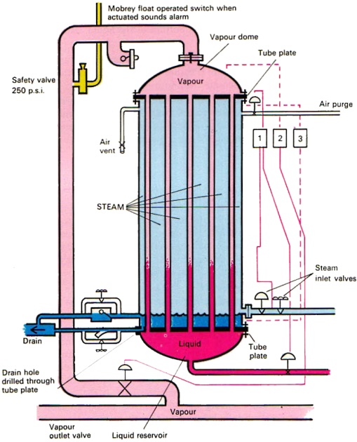
1. Senses steam pressure. Controls liquid admission; 2. Senses vapour pressure in dome. Controls vapour outlet; 3. Indicates liquid level via pressure differenti:
1. Also operates air purge if steam pressure falls below 2 bars
Steam is admitted to the pressure vessel and the steam condensate (water) is drained from the cylinder by two drain lines, one above the other. The upper drain is controlled by a float-operated valve, draining the bulk of the water during operation, but maintaining a level above the drain line to prevent steam escaping via this outlet. The lower drain valve is thermostatically operated and drains the cylinder completely when vaporising is stopped or suspended so as to avoid the water turning to ice due to the possible presence of very cold liquid in the reservoir and no incoming steam to provide heat which would prevent this from happening. Both drains are provided with manual by-passes.
With the pressure vessel hot and under about 4 bars steam pressure, the liquid to be evaporated is slowly admitted into the liquid reservoir. The reservoir fills and a level established in the tubes inside, the level in the tubes being controlled by the steam pressure controller. Evaporation in the tubes takes place and the vapour so made passes into the vapour space on top of the cylinder, whilst the steam condenses into water and is drained away via the drains.
Once working, the automatic control system works in the following manner:
- admission of liquid is controlled by the steam pressure controller;
- the vapour outlet valve is controlled by the vapour pressure controller.
A liquid level indicator working on the differential pressure between the vapour space and the liquid at the bottom of the liquid reservoir indicates the level of liquid in the vaporiser.
To avoid icing up due to a, steam failure, an automatic air purge pressurises the pressure vessel if the steam pressure falls below 2 bars, the air pressure forcing out the steam condensate via the drains.
A safety valve set at 250 p.s.i. is fitted on the dome-shaped cover of the vapour space. A float-operated switch located in the vapour outlet line gives an alarm should the vaporiser completely fill with liquid. A pressure-sensing device shuts off the steam should the vapour pressure in the vaporiser rise above 7 bars.
Type “B”
This type consists of a cylindrical steel pressure vessel into which the liquid to be evaporated is admitted. See Fig. 8.
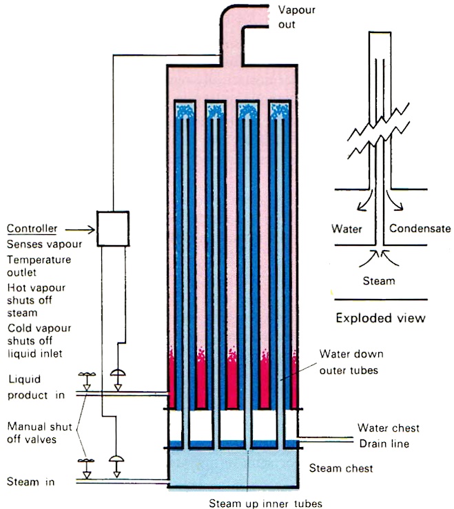
A large number of double tubes is fitted into the cylinder. Up the inner tube of each pair, steam is fed. The outer tube is blanked and receives the steam, which then condenses and runs down into the condensate compartment above the steam inlet compartment. The condensate is drained from the condensate compartment via a float-controlled drain valve.
Various control systems can be fitted. One of them works in the following way. A vapour outlet temperature-sensing device reduces the admission of steam if the vapour outlet temperature is too high and reduces the admission of liquid if the vapour outlet temperature is too low. These temperature controls are usually set about 10 °C. apart, that is 5 °C. either side of the vapour temperature required. They are proportional controls, gradually shutting off the admission of either steam or the liquid to be evaporated, as the vapour outlet temperature departs from its mid-setting so that both the liquid and steam admission valves are fully open at the mid-position. A condensate temperature-sensing device shuts off liquid admission if the condensate temperature falls below a safe level, so there is no risk of the vaporiser freezing. In this system, the vapour-outlet valve is wide open and there is no vapour-outlet control valve.
The advantage of Type “B” over Type “A” is that it is simpler, produces vapour at any required temperature and the condensed water, being over the steam compartment, cannot normally freeze.
Air Dryer
This is used in conjunction with a cargo compressor to reduce the dew-point of the atmosphere in the cargo tanks when they are filled with air after they have been gas-freed and before they have been inerted, by withdrawing air from the top of the tank. The air is discharged through the dryer and returned to the bottom of the tank. See Fig. 9.
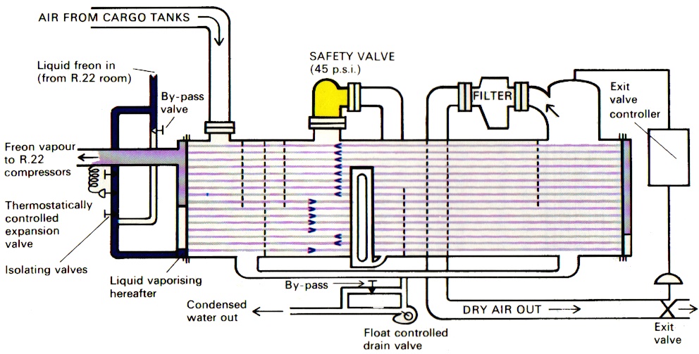
The dryer is Freon-cooled and is similar to a cargo condenser, the liquid Freon evaporating inside the tubes in the dryer. The admission of liquid Freon is controlled by a thermostatically-regulated expansion valve, the sensing bulb of which is in the vapour outlet pipe.
By reducing the temperature of the air passing through the dryer, the water vapour content is precipitated, the rate and degree of precipitation being increased by maintaining a pressure of 1.8 bars whilst the temperature is reduced to +2 °C.
A float-operated valve drains away the condensed water from the bottom of the dryer, the dried air leaving it from the top, passing through a meshed filter. The pressure in the dryer is maintained by a pressure sensitive exit valve.
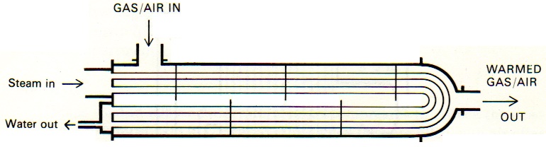
Gas/Air Heater
This is a simple steam heater consisting of an outer vapour shell and into which steam coils are fitted. The vapour space has baffles fitted into it so that the air or gas to be heated zig-zags its way through the heater coils as it passes through the heater. See Fig. 10.
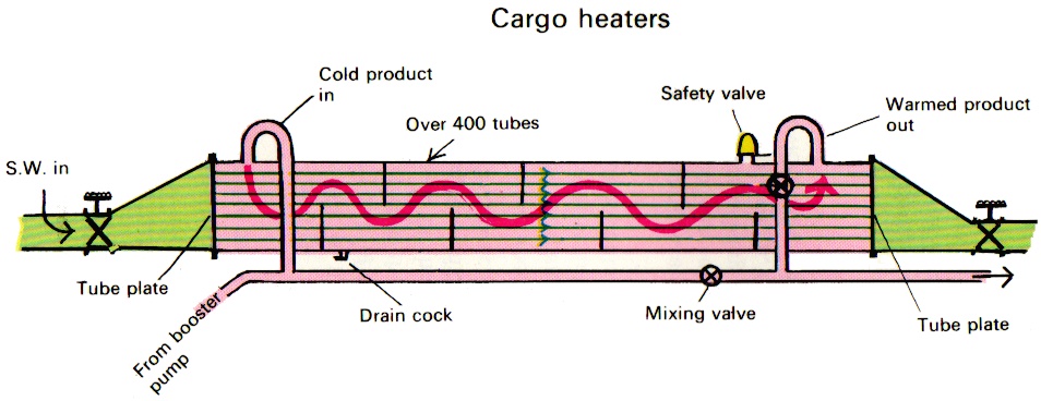
Cargo Heaters
Seawater is used to heat the cargo when it is required to discharge into either ambient temperature or semi-refrigerated shore storage tanks. Two types are described:
Type “A”
Seawater passes through a large number of tubes inside the heater as the product being warmed zig-zags its way through, as shown in Fig. 11.
Type “B”
The product passes through a number of tubes in the heater as shown in Fig. 12, whilst the seawater zig-zags its way through the heater.
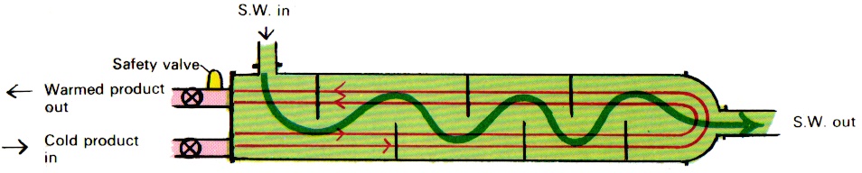
In both types, the heater discharge temperature can be lowered by mixing cold product with the warmed product. The cargo heaters should not be used if the seawater temperature is below 10 °C. The seawater outlet temperature should not be allowed to fall below 5 °C. If there is any risk of this happening, the rate of discharge should be slowed down.
Type “B” is considered to be more reliable than Type “A” for the following reasons:
- If water passing through one or more of the tubes in Type “A” is impeded, there is risk of it freezing and the tube bursting. In Type “B”, however, any risk of freezing would be confined to the water in immediate contact with the tubes containing the product. Ice might form on the outside of these tubes and become an insulating layer. The heater would lose efficiency due to the formation of ice, but it would not cause the tubes containing the product to fracture;
- The ends of the water tubes in Type “A” are fixed and, not being free to move, any uneven expansion between the tubes and the shell could cause the tubes to be strained or even fractured at the tube plate. In Type “B”, the tubes containing the product are free to expand and contract.
Associated with the cargo heater is the Booster Pump. It is used to increase the discharge pressure of the vessel’s cargo pumps. It can be mounted on deck provided the motor driving it is adequately flame-proofed. Otherwise, it is located in the LPG room, driven by a motor in the motor room. The pump should be provided with a by-pass so that the cargo heater can be used without it.
Submerged Cargo Pumps
These are centrifugal pumps driven by a 3-phase electric motor, the stator of which is inside a leak-proof container to which the electric supply leads are connected, the stator and drum forming a sealed unit. See Fig. 13.
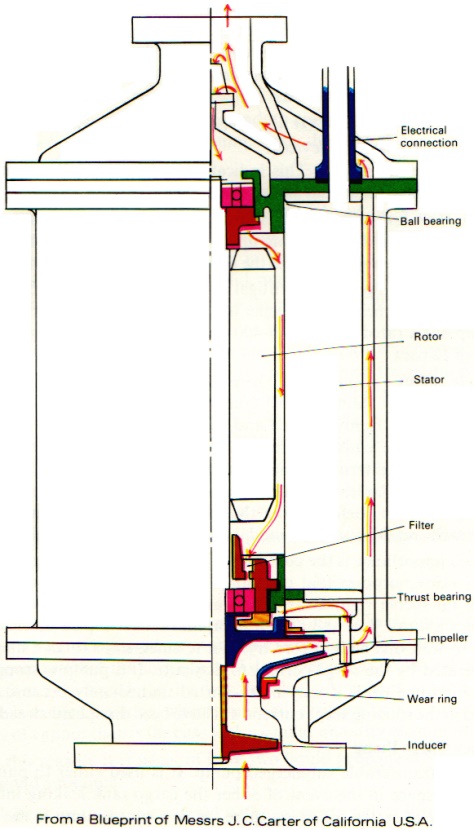
The rotor fits inside the stator drum and drives the impeller immediately below, so that the pump and its driving motor are completely submerged inside the cargo tank.
The pumps, as illustrated, suck through the centre. The liquid discharge section forms a jacket around the pump stator and acts as a cooling agent.
The bulk of the discharged liquid is sent up on deck through the pump discharge pipe, but a small proportion of the liquid is fed back to the pump through the top ball bearing, between the rotor and stator, and through the lower ball race to the impeller, thus cooling and lubricating the bearings and rotor. For this reason, it is absolutely essential that the pump is never run without liquid passing through it.
The pump motor is of 200 h.p., is cooled by the liquid discharge and is protected by the following devices:
- Low current cut-out. This indicates that the pump has lost suction. It stops the pump, and an alarm is sounded;
- High current cut-out. This indicates (apart from starting up) that the pump is seized or is seizing up, or that the impeller has been jammed by a foreign object. It stops the pump and sounds an alarm. Though the pump is a centrifugal pump, it has a small axial propeller called an inducer beneath the impeller to assist (or boost) the suction pressure. The pump has a rated capacity of 400 cubic metres per hour against a back pressure of 12 bars.
Electric supply—pump leads. These are well insulated leads, each phase being in a separate stainless steel conduit pipe, sealed at both ends, each conduit pipe being firmly secured and therefore earthed to the cargo pump discharge pipe. The leads pass through a tight gland at the pump end to the motor terminals and terminate on deck in a watertight junction box near the tank entrance. Similar leads connect the junction box to the distribution panel in the engine room. Before using the pump, the whole system should be megger tested and the pump not used if the megger reading is less than 2 megs.
Of such importance is the continuous flow of liquid discharge for cooling and lubricating purposes that the pump must be stopped at once if it does not pick up suction right away. The starting surge current is so large that it generates a lot of heat and after a pump has failed to pick up suction, it is essential to wait one hour before trying a re-start, so as to give time for the heat generated by the surge current to dissipate. If a pump is stopped after running for some time, it may be re-started immediately because the heat generated in the starting surge current will have been dissipated already.
Emergency Cargo Pump
This is a transferable submerged pump. It is used either to pump out a containment space in the event of either the cargo tank leaking into it or a large quantity of water collecting there, or as a cargo pump in the event of both main cargo pumps failing in a cargo tank.
Emergency pumps are normally rigged in the cargo tanks which, being usually oxygen and water vapour free, would cause less corrosion and damage to the electrical insulation than would be the case if the pumps were kept in the containment space for a long period of time.
The emergency pump is fitted into a trunk way (a tube capable of containing the pump) at the bottom of which is fitted a foot valve which remains shut until the weight of the pump descending upon it causes it to open, so that prior to lowering an emergency pump onto the foot valve, the trunk way should be empty.
The pump is inserted into a tank by removing the trunk way lid on deck and lowering the pump attached to a sectional rod, to which the electric lead is attached. Between each section of the rod is placed a three-legged “spider piece” which centres the rod in the trunk way. The final section of the rod passes through the trunk way lid. and the lid is bolted on the trunk way before the pump is lowered the final few inches onto the foot valve and opening it.
The electric leads are contained in one conduit pipe which passes through the trunk way lid and then secured to the rod by which the pump is raised or lowered. When the pump is stored in a cargo tank, it is not lowered onto the foot valve but kept suspended above it by inserting a small distance piece between the trunk way lid and a flange at the top of the lifting/lowering rod.
When discharging, the liquid comes up the trunk way, filling it completely, the liquid passing through a discharge valve into a short length of pipe which connects it to the main liquid line.
Before transferring an emergency pump, the trunk ways affected should be inerted.
Deck Storage Tanks
These are provided for the purpose of storing sufficient liquid product so that the ship may be gassed-up at sea (the cargo tanks filled with the appropriate vapour) so that the ship can cool down her cargo tanks and be ready to load before arriving at the loading terminal. A greater Questions and answers to Crew Evaluation System Test about Gas Measurementvolume of liquid propane is carried because, when vaporised, propane makes a much smaller quantity of vapour than is the case with a similar quantity of ammonia.
For this reason, it is usual to have two liquid propane storage tanks and one of liquid ammonia. Each deck storage tank is fitted with two safety valves lifting at 210 p.s.i. on the propane tanks and 250 p.s.i. on the ammonia tank. These safety valve settings correspond to the saturated vapour pressure of the products at 45 °C., which is the highest temperature to which the products are likely to rise in transit.
The tanks are so filled that, after allowance has been made for the products to expand as they warm up, they will occupy 98 per cent. of the space when their temperature reaches 45 °C., when the SVP, of the products will equal the safety valve setting. Any further increase in temperature would result in the safety valves lifting and the vapour escaping, so that the product inside the tank boiled, using up latent heat and so automatically refrigerating itself.
To calculate the percentage to fill the tank at any given temperature, the Specific Gravity of the product at 45 °C. is divided by its specific gravity at the temperature loaded, and the result multiplied by 0.98.
Each tank is fitted with a vapour line, liquid filling line and, branching from the liquid filling line, a spray cooling line. In each of the liquid filling lines, spray cooling lines and vapour lines excess flow valves are fitted. These excess flow valves are like non-return valves but with a spring holding open the valve lid. When the flow past the valve lid is such as to overcome the tension of the spring which holds it open, the valve shuts. A small hole drilled through the valve allows the pressure on either side of the valve lid to equalise if a valve downstream of the excess flow valve is shut and the excess flow valve opens again. They are fitted to reduce the flow in the event of a hose outside the tank rupturing, thus preventing an uncontrolled emptying of the tank.
To avoid contamination of each other by the two products, the different sets of lines are completely isolated from each other and are blanked off, and have to be connected to the ship’s cargo lines by a flexible hose when required.
The tanks are provided with two separate water spray cooling lines.
Cargo operating procedure
Loading
Prior to arrival alongside, the vessel’s loading lines should be cooled down by refrigeration. Usually the vessel will have reduced her ballast to the extent that safe handling of the vessel will admit.
At sea, to avoid damage, the tank liquid level-indicating floats are raised and secured at the top of the tank. Also, certain pressure gauges in exposed positions, notably on the vapour and liquid cargo manifold, are unshipped and stowed away. On arrival alongside the loading berth, the removable pressure gauges are shipped in position, and the liquid level-indicating floats lowered from their sea-secured position. The normal safety valve springs are supplemented by stronger harbour springs which increase the pressure at which the safety valves operate. The reliquifaction system is usually kept running and the tank pressures should be low (about 0.02 bar). After the loading lines have been connected and the tank readings agreed with the shipper’s representative, loading may commence.
The tank temperatures may not be quite as they should be on arrival if, due to gas-freeing or changing grades, there is insufficient liquid on board. If so, the tanks, although pre-cooled as far as possible, may need further cooling. This is done by opening the cross connection between the liquid loading line and the condensate line, and receiving product very slowly through the spray lines. The liquid, as it is sprayed into the tanks, will evaporate, use up latent heat and so cool the tank, but at the same time, due to the increase of vapour present in the tank, the vapour pressure will rise.
If a shore vapour return line is provided, the excess pressure may be relieved by returning the vapour ashore. Otherwise, it may be relieved by refrigeration, but due to the high pressure set up in the condensate line resulting from the restricting effect of the spray outlets, “spraying in” has to be suspended because the condenser pressure is insufficient to send the condensate back to the tank against the high loading pressure. (Sometimes the liquid can be sprayed into one tank and the condensate sent back to another.)
When the presence of liquid is well established at the bottom of the tank and the tank is cold, loading proper may commence by opening the liquid loading valves and increasing the loading rate.
Whilst loading, although the tanks are cold, the compression of the vapour trapped in the space above the rising liquid level will lead to an increase of vapour pressure. This pressure can be relieved by refrigeration, which is usually better than returning the vapour ashore, because the returned vapour often goes to a flare and is wasted. There may, however, be some good reason, such as the presence of incondensibles or impurities, which override this consideration.
During loading, the vessel has to be further deballasted. Care should be taken to keep the vessel upright at all times, which means keeping the cargo even and the ballast even. Because the sounding pipes are near the ship’s centre line, if the vessel develops a list, the slack ballast water will run towards the sounding pipe on the “high side” and away from the sounding pipe on the “low side”. This may mislead the officer on watch to assume that there is more ballast on the “high side” than there is on the “low side” when, in fact, the opposite is the case, and he may look for other factors (usually bunkers) to account for the list. The cargo is similarly affected. See Fig. 14.
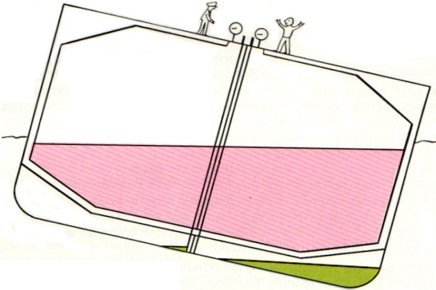
If the vessel does develop a list during the course of loading, the best way to correct it is to bring the vessel upright with the cargo, adjust the ballast, keeping the vessel upright all the time, and level of the cargo.
The maximum safe loading rate varies from ship to ship but is usually about 500 cubic metres per hour per tank valve open. When loading part cargoes, the loading rate should be reduced accordingly.
During loading, a regular check on all tank soundings must be kept. It is particularly important to keep a check on any tank that has already been filled to ensure that, due to some leaky valve or any other reason, no more liquid enters the tank and so over-fills it.
Completing Loading
High level alarms operated by the tank liquid level indicating device sound at approximately 95 per cent. and 97 per cent. capacity. As each set of tanks is completed, the loading rate is reduced as the loading valves are shut. The vessel is normally loaded to 97 per cent. capacity which corresponds to 98 per cent. when allowance is made for the cargo to expand to the temperature at which its saturated vapour pressure equals the safety valve settings (4.25 p.s.i. or 0.3 bar). In practice, this works out as follows:
If by any chance, the shore operators are too slow in shutting off the cargo on completion, the overfill float switches (usually set at 98.5 per cent. capacity and completely independent of the tank liquid level indicating device) operate and shut the loading manifold valve. This is a slow operating valve taking 15 seconds to shut to minimise the surge effects in the shore loading line, the reasoning being that it is better to risk rupturing a loading hose than to rupture a cargo tank. The surge pressure effect is caused by the sudden stopping of the flow of liquid in the loading pipeline. The weight of liquid moving in the shore pipeline acquires considerable kinetic energy and, if suddenly stopped, causes a dramatic surge in pressure. Even 15 seconds is not enough to stop the surge pressure and most modern installations have either a circulating line with a bursting disc or a special surge tank which fills when the bursting disc is ruptured.
The harbour springs should be removed from the safety valves as soon as practicable after loading has been completed and, in any case, before proceeding to sea.
To Refrigerate the Cargo on Passage
In both two-stage and cascade cooling systems, steam is withdrawn from the cooled tanks, liquefied and returned to the tanks as a liquid. The technique varies with the type of reliquifaction plant used.
Two-stage Reliquifaction
Before starting the plant, the flexible couplings on the drive shaft in the motor room and LPG room must have been greased. The grease hardens after a time and the grease should be completely changed periodically (about once a month). The bulkhead seal cooler must be seen to be full of liquid and there must be no blockage in the system.
Further checks are:
- that the compressor is turned manually by inserting a bar into the flywheel and rotating it to ensure that the compressor is free to run;
- that the oil in the compressor crankcase is at the correct level and temperature;
- that water is running through the condenser, and is available for the oil cooler;
- that the oil return valves on the return lines leading from the oil separator traps on both the LP and HP stages to the compressor crankcase are shut;
- that the discharge valves on the LP and HP stages of the compressor are open;
- that the compressor HP suction valve is open and the LP suction valve is shut, but free to move; and
- that there is no liquid in either the heat exchanger or the inter-stage cooler.
The compressor may then be started. As the LP suction pressure falls, the suction valve should be opened slowly, and the rise in oil and vapour discharge pressures carefully watched. The suction valve must be shut and the compressor stopped immediately should the vapour discharge pressure rise abnormally. As liquid forms in the condenser, the inter-stage injection system should be placed in service.
The vapour suction temperature must be carefully watched at the time of starting-up, particularly the LP suction temperature which, if unduly high, will so increase the discharge temperature of the LP stage as to actuate the LP discharge temperature cut-out, causing the compressor to stop.
If necessary, the LP vapour suction must be cooled by injecting liquid taken from the condenser into the vapour line just before it enters the heat exchanger. The pipe through which the liquid is injected is of very small diameter and there is little risk of liquid accumulating in the heat exchanger when using this cooling system. The evaporation of the injected liquid uses up latent heat and cools the vapour before it goes to the LP stage of the compressor. When the cold vapour from the tank arrives, the liquid injection should be shut off.
The liquid level in the condenser must be watched to ensure that the float-controlled outlet valve is functioning correctly. (Liquid should only show in the bottom of the condenser gauge glass.) The condensate return pressure is checked to ensure that no sprays or filters are impeding the flow back to the tank. In this connection, the filter traps on the condensate line should be cleaned out and filled with methanol prior to loading.
After the compressor has been running some time and the bottoms of the oil separator traps are warm, the return valves on the lines leading from the traps to the compressor crankcase are opened, and the oil heater in the crankcase isolated and the lubricating oil cooler used.
Points to Watch Whilst the Plant is Running
A record should be kept of the plant, covering mainly seawater temperature, condenser pressure, compressor LP and HP suction/discharge temperatures and pressures, oil pressure, condensate return pressure, etc. Trends are as important as the actual readings.
The state of the compressor cylinder heads should always be under observation. If a cylinder head is unduly cold, this indicates a wet suction; it means that liquid droplets are entering the compressor and vaporising during compression, the latent heat of vaporisation removing the heat which would otherwise be gained in the adiabatic process and is a warning of an excessive quantity of liquid having collected in either the heat exchanger or inter-stage cooler. The compressor must be stopped, the excess liquid drained away and the float cut-out switch checked for malfunction.
If a cylinder head is unduly hot, this indicates a faulty suction valve plate or discharge valve plate. The compressor should be stopped and the valve plates, checked.
The compressor is stopped by shutting the LP suction valve, thus taking the compressor off load, and then stopping the compressor.
As soon as the compressor is stopped, the isolating valves to the interstage cooler and the heat exchanger cooler should be shut to exclude the possibility of these filling with liquid from the condenser during the stoppage.
The lubricating oil heater should be placed in service so that the compressor is ready to start when next required.
During a prolonged stoppage of the compressor, it should be turned daily by hand to distribute the wear on the motor bearings (the steady vibration of the ship causes wear on the ball bearings if kept stationary).
Cascade System of Reliquifaction
In this system there are two sets of compressors and condensers, the Freon or R.22 system and the cargo system, the R.22 system cooling the cargo condenser.
The first step in starting the cascade reliquifaction system is to check that the pumps which provide cooling water for the R.22 condensers are in service, and that power is available for both the R.22 and cargo compressors. The procedure is then as follows:
1. In the R.22 Room, the following checks must be made:
- that the oil levels in the R.22 compressors are correct;
- that the level of Freon in the R.22 receivers is correct;
- that the following valves are shut:
- the compressor suction valve;
- the oil return valve from the separator trap;
- the R.22 receiver liquid outlet valve to the expansion valves on the cargo condenser.
- that the following valves are open:
- the R.22 compressor discharge valve;
- the valve between the R.22 condenser and the R.22 receiver.
- that the solenoid valve on the same line as the liquid outlet valve is free by running the jack the full length and returning it to its original position;
- that the R.22 compressors are unloaded;
- (that the header tank is full on the LPG system in the R.22 room;
- that the LPG circulating pump is running (it is usually left running because, whilst it cools the compressor when the compressor is running, it warms it when it is stopped).
2. In the LPG Room (R.22 system)
- that the isolating valves which direct the Freon to the air dryer are shut, and that all isolating valves and by-pass valves on the dryer are shut;
- that the by-pass valves to the thermostatically-controlled expansion valves on the cargo condenser are shut, and the isolating valves on either side of each thermostatically-controlled expansion valve are open.
3. In the LPG room on the cargo side of the system
- that the lubricating oil levels in the cargo compressors are correct;
- that all the fault-indicating lights are extinguished (if illuminated, the appropriate re-set button is pressed);
- that the compressor suction valve is shut and that the compressor discharge valve to the condenser is open;
- that the purge relief valve controller is set to the approximate setting for the product to be refrigerated, i.e. 3 bars for butane, 4 bars for propane and 5 bars for ammonia;
- that the oil-operated unloaders on the compressor are set in the unloaded position;
- that the isolating valves on either side of the float-controlled condenser outlet valve are open; and
- that the purge condenser and tank return valves on the condensate line are shut.
To Start the Compressors
Great care must be taken when starting the R.22 compressors, particularly if the system has been shut down for any length of time and the cargo condensers have become warm. With the cargo condensers warm, the thermostatically-controlled expansion valves through which liquid Freon is admitted to the condenser will be wide open. The solenoid-operated valve on the Freon outlet line opens as soon as the R.22 compressor is started and, unless the manual liquid outlet valve is shut, the initial gush of liquid will fill the condenser before it has had time to evaporate and some liquid may be carried over to the compressor suction. To prevent this, the condenser must first be cooled by manually operating the liquid outlet valve until the temperature of the condenser reaches zero centigrade, when the thermostatically-controlled expansion valves will operate automatically.
In the R.22 room, the R.22 compressor low suction cut-out must be turned back to zero. Then the compressor suction valve is cracked open and the compressor started. The oil pressure, suction and discharge pressures must be watched, the compressor being stopped at once if anything is amiss. At first, the suction pressure may be rather high due to liquid Freon having been left in the cargo condenser when the system was shut down on the previous occasion and having subsequently evaporated. The suction pressure should drop quite quickly and, as it falls, the compressor suction valve is opened so as to maintain a pressure of about 3 bars. With the suction pressure at 3 bars, slowly open the liquid outlet valve from the R.22 receiver, adjusting it in such a manner as to maintain this pressure. The R.22 compressor is loaded up to 50 per cent. capacity.
As the temperature in the cargo condenser falls, it is reflected in the vapour suction temperature of the R.22 compressor, and by the time it reaches zero centigrade, the automatic thermostatically-controlled expansion valve should be working and the liquid outlet valve fully opened.
During this start-up period, the temperature of the cylinder heads on the R.22 compressor must be carefully watched as there is always a risk of wet suction. If the cylinder head or heads go cold, the Freon outlet valve must be shut. With a very warm cargo condenser, cooling the condenser can take in excess of half an hour.
With the cargo condenser cold and the automatic expansion valves in operation, the cargo compressor may be started. The compressor suction valve is opened and the compressor started. As soon as the compressor is running satisfactorily, the compressor load is increased to 75 per cent. capacity, and the purge condenser and tank return valves on the condensate line are opened.
The condensation of the cargo vapour inside the cargo condenser gives extra heat, so evaporating more Freon and increasing the pressure on the R.22 compressor suction. The loading of the R.22 compressor should be increased, loading the cylinders one at a time in such a manner that the R.22 suction pressure does not fall below 1.5 bars nor rise above 3 bars. This is continued until both cargo and R.22 compressors are running at full capacity. With both R.22 and cargo compressors running, the R.22 low suction pressure cut-out is re-set to 1 bar.
The next pair of compressors may be started in like manner. As soon as possible after the plant is running, the methanol injection pump should be placed in service. This is particularly important after the vessel has been gas-freed because of possible increase in the water content due to the absorption of water vapour when the vessel was gassed-up. The stroke of the methanol pump is usually adjusted to about 15 per cent. on starting; after about 2 hours, the stroke is reduced to about 4 per cent.
When the reliquifaction plant has settled down, the purge condenser release valve controller is adjusted from its rough setting to slightly above the condenser pressure.
When refrigerating butane, it is essential to maintain at least 1 bar pressure in the condenser to drive back the condensate to the cargo tanks and the cargo compressor should never be off-loaded to such an extent that the condenser pressure falls below 1 bar or there will be a risk of the condenser priming (filling with liquid).
Points to Watch Whilst the Plant is Running
No condensate must appear in the cargo condenser. If condensate is seen, this indicates that either the condenser pressure is too low, or that a blockage exists in the condensate outlet (probably ice or hydrates). The blockage is usually cleared with methanol.
The temperature of the condensate between the condenser and the float-controlled outlet valve must be checked and if it warms up the compressor should be off-loaded.
If for no apparent reason the suction temperature on the R.22 compressor rises, it indicates that there is insufficient Freon in the system and that the Freon needs replenishment. This rise in temperature is the first noticeable manifestation of a shortage of refrigerant in the system; a noticeable drop in the suction pressure follows.
To replenish the Freon, a bottle of liquid Freon is connected to the valve on the liquid line which supplies the cargo condenser with liquid Freon. The valve on the Freon bottle and the valve to which the Freon bottle is connected are opened and the liquid outlet valve from the R.22 receiver is partly shut so that liquid Freon from the bottle supplements the reduced quantity supplied from the Freon receiver. In this way, Freon from the bottle augments the supply by being evaporated in the cargo condenser and then reliquified in the R.22 condenser.
To Shut Down the System
The first action is to unload the cargo compressor and then reduce the loading on the R.22 compressor to 50 per cent. The low suction pressure cut-out is wound right back and the liquid outlet valve of the R.22 receiver shut. With the cargo compressor still running, but no more liquid being supplied to the cargo condenser, the liquid already present will be evaporated until eventually the R.22 compressor suction pressure falls and the compressor stops itself on the low suction pressure cut-out. As soon as the R.22 compressor stops, the suction and discharge valves of the compressor are shut.
The cargo compressor is then stopped and the suction and discharge valves shut. The cargo condenser is allowed to empty itself into the cargo tank. Then the condensate valves are shut. Finally, the purge release valve is opened by re-setting the controller to zero pressure so that any trace of liquid cargo remaining in the condenser can evaporate and escape under atmospheric conditions.
Other Points to Watch
Freon is expensive and, to conserve it, all valves on the Freon system are provided with hooded covers and adjustable glands. The glands should be tightened except when it is required to move a valve; and the hoods should be replaced when the valves are not being used. This is particularly important if the R.22 plant is to be shut down for any length of time. When checking the level of Freon in the receiver tank, allowance must be made for the Freon in the cargo condenser when the plant is running.
Discharging
The procedures correspond very precisely to those (General Principles of Operation) that should be referred to. Prior to arrival alongside at the discharging terminal, the deck liquid lines must be cooled by returning the condensate to the cargo tanks via the deck liquid lines. The cargo pumps should be megger tested and not used if the megger readings are below 2 megs.
On arrival alongside the discharging berth, once the discharge lines have been connected and the tank readings agreed with the receiver’s representatives, the discharge may commence. The pump discharge valves are opened about two turns and a loading valve partially opened and the pump started. The discharge pressure and pump ammeter readings must be carefully watched. If the pump does not show a discharge pressure very quickly, it is an indication that the pump has not picked up suction and the pump should be stopped at once. After the initial starting surge, the ammeter reading should show about 180 amps, but the exact reading should be compared with the consumption graph in the maker’s handbook, and the pump stopped if the ammeter reading exceeds 10 per cent. of the rated output. Once started, the pump discharge valve should be regulated so as to maintain a discharge pressure of about 7.5 bars on the pump.
Once the product is going ashore, the loading valve must be shut. During the course of the discharge, the tank pressure should be watched and never be allowed to fall below 0.02 bar to exclude the risk of a slight vacuum being created on the tanks. If a shore vapour return line is provided, this should present no problem, but if none is fitted the vaporiser should be started up, drawing liquid from the liquid discharge line and discharging the vapour into the vapour line.
As the level of liquid approaches the bottom of the tank, a careful watch must be kept on the discharge pressure and ammeter readings of the pump. The initial warning of low suction pressure is a fluttering of the discharge pressure and ammeter gauges. The discharge valve must be closed slightly to maintain a steady pressure and, if necessary, the loading valve must be opened slightly to increase the flow of liquid through the pump, thereby increasing the ammeter reading. In this manner, the tanks can be pumped down to a level of about 15 centimetres, when the pump becomes difficult to control and must be stopped (unless it has stopped itself under low current).
In the event of the pump stopping or being stopped during discharge, only one re-start may be attempted. If suction is not picked up right away, no attempt to re-start may be made for one hour in order for the heat generated during the starting surge to dissipate.
When discharging through the cargo heater using the booster pump with a shore back-pressure restriction, control of the booster pump discharge pressure is best regulated by varying the pressure on the booster pump suction, as opposed to partially closing the booster pump discharge valve. The pressure on the booster pump suction is lowered by circulating part of the liquid discharge by the main cargo pump back into the tank by slightly opening the tank loading valve. This gives far better control.
To Gas-free the Vessel
The main principle underlying safe gas-freeing is to ensure that no air/ LPG vapour mixtures form and, if they do, that they are neither compressed nor heated. After ensuring that the condensers are free of all liquid, the gas-freeing operation falls into four distinct phases, namely:
- puddle heating;
- tank warming;
- inerting;
- flushing through with air.
Puddle Heating
The first step is to evaporate the residual liquid left behind after completion of the previous discharge. A decision will have to be taken at this stage, whether to save the liquid by transferring it into the deck storage tank, or into another tank if only one tank is to be gas-freed, or to release the product over the side via a flexible hose.
To puddle heat, the lines are set so that the compressors suck vapour from the tanks to be gas-freed and discharge it into the puddle heat coils (usually via a cross connection into the ship’s liquid line and from the liquid line into the puddle heat coils, the returns coming up the puddle heat return line into the condensate line for disposal). Then the compressors are started and the puddle heat return valves adjusted to maintain a pressure of about 3 bars in the coils. This pressure assists with liquifaction inside the coils because, under this pressure, the vapour will condense at a temperature much higher than that of the surrounding liquid, which is acting as a cooling agent, and so readily condenses. When puddle heating propane, there is a constant risk of the coils icing up. This is because propane can absorb more water as a vapour than it can as a liquid so that some of the water content may settle out during-the process of liquifaction and freeze. The principal indications of icing-up in the coils are:
- the affected coil return may be less frosted than those unaffected; and
- the inlet pressure rises.
If icing-up is suspected, the inlet valve should be closed slowly. If a hissing noise is heard, combined with a rise in inlet pressure, it indicates that that particular coil is clear or has cleared itself. If no hissing noise is heard, the coil is iced up in the tank. When a coil is blocked with ice, the easiest way to clear it is to stop the compressors, insert methanol into the coil, and then re-start the compressors.
During the course of puddle heating, the vapour pressure in the tank tends to rise slowly. When this happens, the excess pressure may be reduced, either by releasing the excess pressure up the mast, or by refrigeration (if it is decided to recover the product).
When all the liquid in the tank has been evaporated, the return coils defrost themselves. It is usual to continue puddle heating until no liquid emerges from the puddle heat discharge, as a preliminary to tank warming, particularly if no gas/air heater is fitted, because the release of latent heat due to condensation is the most efficient way to use the compressors, and condensation should take place whilst the tank temperatures are substantially sub-zero.
To Estimate the Time it Will Take for Puddle Heating
The quantity of liquid remaining in the tanks is first calculated. Then, by allowing 1.3 tons for every 1,000 cubic metres passed through the compressors each hour, the hourly air through-put can be calculated. This is then multiplied by the density of the vapour relative to air.
Example:
How long will it take to evaporate 90 tons of (a) propane and (b) ammonia with three compressors each of 1,000 cubic metres per hour capacity?
Compressors’ hourly through-put of air = 3 x 1.3 = 3.9 tons:
- (a) For propane: hourly through-put of vapour = 3.9 x 1.5 = 5.85;
Therefore time taken will be 90/5.85 = about 16 hours:
- (b) For ammonia: hourly vapour through-put = 3.9 x 0.6 = 2.34 tons;
Therefore time taken will be 90/2.34 = about 38 hours.
It will be seen that ammonia takes considerably longer to puddle-heat than does propane.
Tank Warming
After all the liquid in the tanks has been evaporated by the puddle heat coils, the tanks are warmed by circulating the vapour using the compressors, drawing vapour from the top of the tanks and returning the vapour through the gas/air heater (if fitted) to the bottom of the tanks. The circulation of the vapour warms up the cargo tanks and evaporates any final trace of liquid remaining after the puddle heating operation. (Traces may be left underneath the puddle heat coils.) The operation is considerably speeded up if a gas/air heater is fitted. It is important to carefully perform the operation of warming up the tank to avoid any possibility that any liquid will remain in the tank, because if any liquid remains, it will evaporate during inertia in the next stage, which will completely upset this operation.
When the tank warming operation has been completed, the method of gas-freeing differs according to whether gas-freeing takes place after an ammonia cargo or after an LPG cargo. After an LPG cargo, it is necessary to inert the cargo tanks. After an ammonia cargo, it is not.
Inerting the Cargo Tanks
In this operation, inert gas supplied from the inert gas generator in the engine room is fed into the top of the cargo tanks via the upper purge line, and the LPG vapour displaced from the bottom of the tanks via the lower purge line and released up the mast. If purge lines are not fitted, the vapour and liquid lines are used instead. Because inert gas is lighter than LPG vapour, it forms a layer over the LPG vapour and there is not much admixture between the two. It is an advantage if the cargo tanks can be inerted in series (i.e. the inert gas following the LPG vapour from the bottom of one tank to the top of the next until the final tank releases the vapour from the bottom of the tank up the mast, but not all ships have this facility).
Flushing Through with Air
After the tanks have been inerted, the inert gas and any final traces of LPG vapour are flushed through with air. using the compressors (or air blower, if provided), the air following the same path as the inert gas. Flushing through with air continues until the tanks are completely gas-free.
In the case of ammonia, the air. being heavier than ammonia vapour, is fed into the bottom of the tanks and the ammonia vapour displaced from the top, being released up the mast. Flushing through with air should continue until the concentration of ammonia vapour is reduced to about 700 p.p.m., when the tank lids can be opened and the ventilation supplemented by air-driven fans which, by using chutes, deliver more air to the bottoms of the tanks, the ammonia vapour welling out through the tank lids until the ammonia vapour concentration is reduced to below 20 p.p.m. The tanks can then be considered gas-free.
Preparing the tanks to receive cargo after they have been gas-freed
Drying the Air in the Cargo Tanks
The presence of water, even in the smallest quantities, is always a source of embarrassment to the gas tanker operator because, under operating conditions, it turns to ice. Although the tanks may be superficially dry when the vessel is free of “gas, the water vapour content of the air will condense when the vessel cools down. It is therefore a great advantage to reduce the dew point of the air as low as possible. In the drying operation, air is sucked by the cargo compressors from the top of the cargo tanks and discharged into the dryer, where the air is cooled under pressure and the bulk of the water vapour content condensed and drained away. From the dryer, the air is sent to the gas/air heater, where it is warmed and then returned to the bottom of the cargo tank. The dried warm air is so undersaturated as to absorb readily any moisture which has condensed on the tank sides.
To Operate the Air Dryer
The Freon-cooled air dryer uses Freon taken from the system, which normally cools the cargo condensers when the reliquifaction plant is in service, but, being of much smaller capacity, only one R.22 compressor is used, running at 25 per cent. capacity.
The first step is to isolate the cargo condensers and connect the dryer to the R.22 system by shutting all the valves which admit Freon to the cargo compressors and opening all the valves which direct the Freon to the air dryer. On the dryer itself, the valves which isolate the thermostatically-controlled expansion valves should be opened, but the valve which by-passes the automatic expansion valve should be shut.
Then the R.22 compressor is started and the dryer is cooled to cool the cargo condenser; but in this case, the compressor R.22 remains running at minimum (25 %) power.
With the dryer cold, a cargo compressor is started. The dryer outlet valve is adjusted to maintain a pressure of about 1.8 bars in the dryer and, as the plant settles down, more cargo compressors may be brought into service.
Steam is then applied to the gas/air heater and the air in the tanks dried and warmed.
To Inert the Cargo Tanks prior to Gassing-up with L.P.G. Vapour
The inert gas generated by the inert gas generator is fed into the tanks. Inerting should continue until the oxygen content in the cargo tank is reduced to below 8 per cent.
To Gas-up the Cargo Tanks
If the vessel is fitted with deck storage tanks, this operation can be carried out at sea, and is rather like gas-freeing in reverse. When preparing the ship to load an LPG cargo, it is usual to gas-up with propane vapour. This is done by taking liquid propane from the ship’s deck storage tanks, vaporising it in the vaporiser and sending the vapour so produced into the bottom of the cargo tank to displace the inert gas out through the top, where it is released to the atmosphere.
Before loading ammonia, liquid ammonia is vaporised and the vapour so made fed into the tops of the cargo tanks, displacing the air from the bottoms of the tanks up the mast where it is released.
In both cases, it is a great advantage to use the appropriate purge lines’ (if fitted) because these distribute the vapour and collect the air or inert gas evenly and so greatly assist the stratification and cut down the degree of admixture due to turbulence. The vapour and liquid lines have to be used if purge lines are not fitted. It is also an advantage if the tanks can be gassed-up in series because this makes better use of the vapour and reduces the presence of incondensibles remaining, particularly in all but the very last tank in the series.
If no deck storage tanks are provided, then the operation of gassing-up the cargo tanks must be done alongside the loading berth.
If the shore can provide vapour and a vapour return line, the tanks can be gassed-up by introducing LPG vapour to the bottom of the tanks and returning to the shore inert gas from the top (and vice versa for gassing-up with ammonia).
If the shore can provide a vapour return line but can supply only liquid, then the liquid can be vaporised in the ship’s vaporiser and the vessel gassed-up, returning the inert gas to shore in the same manner as described above.
To Gas-up the Tanks when no Shore Vapour Return Line is Provided
In this case, a great deal depends upon what procedures the shore authority will agree to. The easiest way is to gas-up the ship in the same manner as is done at sea. Liquid is taken from shore and vaporised. The displaced inert gas-vapour mixture is released up the mast. However, the authority may not agree to this, but it may agree to gassing-up one tank, using one or more other tanks as buffer tanks. This is easy to do if the layout of the ship line allows the tanks to be filled with gas sequentially, otherwise it is necessary to follow the procedures.
In this connection, many terminal authorities argue that it is safer to gas-up at sea because, on a calm day, the ship can create its own wind and there is little risk of LPG vapour descending and creating a concentration on and around the ship’s decks. Additionally, they do not wish to have any vapour, either LPG or ammonia, drifting round their installations, although it is considered that the concentrations, being minimised by stratification effect and diluted with inert gas, are much weaker than those emitted from Crew Evaluation Test online for seamans about Crude Oil Washingcrude oil tankers when loading. In fact, for the bulk of the gassing-up period, the concentration of LPG vapour in the inert gas is only in the region of 2 per cent, rising sharply only in the final stages.
Cooling down the Cargo Tanks prior to Loading
If the cargo tanks have been gassed-up at sea, the reliquifaction plant is put into service and the tanks cooled. In this way, the tanks are cooled gently and evenly, but with no liquid in the tanks it may not be possible to reduce the tank temperature to loading level, in which case the final cooling takes place alongside by spraying in liquid.
When cooling down alongside, liquid is taken from shore and, in conjunction with the ship’s reliquifaction plant and a shore return line, the pressures created by the evaporation of the liquid taken can be controlled.
Procedure when changing grades and types of cargo
- From ammonia to LPG:
- Gas-free the tanks, dry the air, inert, gas-up and cool down, so that the vessel is ready to load. Particular care must be taken to reduce the ammonia content to below 20 p.p.m. when gas-freeing and, when loading in the Persian Gulf area, to below 5 p.p.m. In this connection, it is probable that the concentration of ammonia in the cargo tanks will be further reduced during the gassing-up process.
- From LPG to ammonia:
- Gas-free the tanks, dry the air and then gas-up with ammonia vapour and cool down. If gassing-up has to be carried out alongside, and the loading authority insist that the tanks be inerted prior to gassing-up, pure nitrogen must be used and not inert gas from the inert gas generator because the carbon dioxide content and other impurities present in the gas supplied from this source will form carbonates.
- To change grades between the following products:
- Butane, butene, butadiene, propane, propene.
It is sufficient to puddle heat the liquid out of the tanks and then cool down. Because butene (butylene), propene (propylene) and butadiene are un-saturated hydro-carbons, they require an oxygen-free tank. For this reason, one should never gas-free the tanks prior to loading them (unless following an ammonia cargo), when the tanks must be inerted to reduce the oxygen content to below 2 per cent. in the case of propene and butene and 0.2 per cent. in the case of butadiene.