Unlock the intricacies of LNG carrier cargo pumps with our comprehensive guide. From understanding their purpose and principles to mastering operational procedures and maintenance, ensure optimal performance and safety on board. Explore everything from starting systems to alarm settings in this essential resource for LNG carrier operators and engineers.
Reference: SIGTTO “LNG Shipping Suggested Competency Standards”, Sections:
1 Have an awareness of their purpose and operating principles:
- location and typical number.
2 Know and understand their principles, operating parameters and limitations:
- design features;
- pressure, vacuum, suction, flow and head.
3 Know and understand operational requirements and procedures:
- the operational requirements with respect to limitations on number of starts, flow limits and required liquid level;
- correct starting sequence;
- pump control;
- setting up;
- starting and restarting;
- the use of automatic control sequencers;
- shutdown.
4 Know and understand their alarm settings and resulting actions.
5 Know and understand the starting system:
- maintenance;
- testing;
- emergency starting arrangements.
6 Know and understand the pump motors and cabling:
- maintenance;
- testing.
Submerged pumps
Submerged pumps are used on LNGC and the low temperature of the cargo is used as a cooling medium for the submerged electric motor.
| Cargo pumps/typical details | |
|---|---|
| Capacity | between 1 500 m3/h and 2 100 m3/h · 155 mLc |
| No. per tank | 2 |
| Power | from 410 kw to 650 kw |
| Speed | 1 800 rpm |
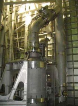
The pump assembly and electric motor are installed in the bottom of the cargo tank. In older models, power is supplied to the pump motor through copper or stainless steel sheathed cables, which terminate in a junction box at the cargo tank dome. For current designs, cryoflex cabling is the preferred choice.
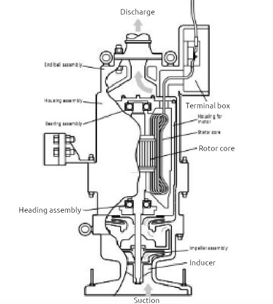
The pump is lubricated and cooled-down by the surrounding cargo.
Note: If the pump were to be mounted on deck, it would need to be of a much larger capacity to draw the liquid up and would require a substantial cooling arrangement.
Design features
Each main cargo pump is typically rated to discharge at 145 m head of LNG at a typical flow rate of 1 500 m3/h. For optimum discharge, 2 cargo pumps will be running in each tank, with all pumps running in parallel. On ships with a Cargo Containment Systems of LPG and LNGsmaller forward cargo tank, it is beneficial to use only one pump when discharging it.
Pumps are designed with inducers and bell mouths to provide minimum net positive suction head (NPSH) requirements and to be fully hydraulically thrust balanced in normal service over a wide capacity range.
Operating a pump at, or close to, its design flow level is in the best interests of the pump lifespan and operating performance. However, operating the pump at lower flow rates cannot always be avoided. This is particularly the case when the shore receiving facility cannot accept the rated flow and when approaching the stripping level or during stripping. The pump’s rated flow should only be exceeded during the starting period, while the discharge valve is adjusted.
Stripping or low liquid level operation
As the end of a discharge approaches, the pump suction head will approach the NPSH for a given flow. At approximately 0,8 to 1 m liquid level above the pump inlet bell, the NPSH for the rated capacity will be reached. When the amount of liquid falls to this level, the motor ammeter and the pump discharge pressure should be monitored continuously by the operator.
Total head curve (green)
This shows the capacity of the pump as a function of the head developed by the pump. Capacity is given in terms of volumetric flow rate, normally m3/h (Q), while head (H) developed by the pump is given in terms of metres liquid column (abbreviated to mLc). Adopting these parameters of volumetric flow rate and head means that the capacity/head curve is the same for any fluid.
Taking the capacity curve shown in Figure 4, this pump will deliver 40 m3/h with a head of 180 mLc across the pump.
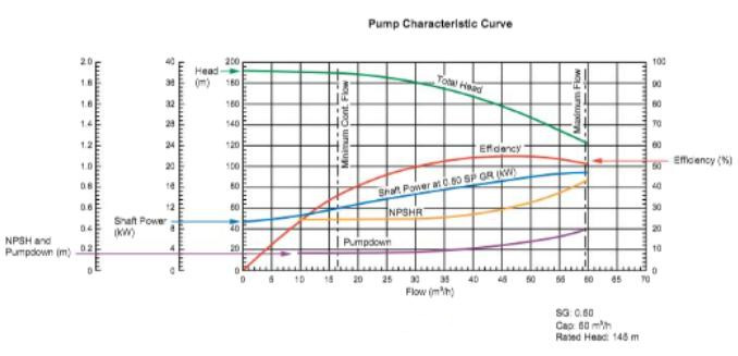
To convert this head into a differential pressure reading in bars, the specific gravity of the fluid being pumped must be known. For example, at a differential head of 180 mLc for this pump, the differential pressure across the pump pumping LNG at minus 161 °C (-161 °C – SG approx. 0,5) would be 9 bars.
NPSH curve (yellow)
This shows the NPSH requirement for the pump in question as a function of pump capacity. The net positive suction head requirement at any flow rate through the pump is the positive head of fluid required at the pump suction to prevent cavitation at the pump impeller.
For example, at a capacity of 40 m3/h the NPSH requirement for the pump is 0,2 mLc. This would mean that with a flow rate of 40 m3/h a minimum head of cargo equivalent to 0,2 m would be required at the pump suction to prevent cavitation.
NPSH considerations are particularly significant when pumping Properties of liquified gasesliquefied gases because the fluid being pumped is always essentially at its boiling point. It must be remembered that, if cavitation is allowed to occur, not only will damage occur to the pump impeller but the shaft bearings themselves will be starved of cargo for cooling and lubrication and bearing damage will quickly result.
Power curve (blue). This shows the power absorbed as a function of pump capacity.
Operational limits
The low level alarm is triggered when the liquid level is about 1 m above NPSH (at ~2 m sounding). The flow should be reduced by use of the throttling valve on the pump discharge side.
If any fluctuations are observed on the motor ammeter or on the pump discharge pressure gauge during final pumping, the discharge flow rate should be further reduced until the readings stabilise. When the flow is throttled down to about 230 m3/h the required NPSH will be about 10 cms. This level represents the minimum level attainable by pumping, but it will vary by pump.
Caution
It is critical that the pumps are never allowed to run dry, even for short periods, as this will result in failure. A momentary loss of priming during cargo stripping should not be considered as running a pump dry. Up to 30 seconds of operation with dry suction,but with fluid in the discharge pipe, will not damage the pump or the motor. However, pumps are fitted with safety features to prevent abnormal operation e. g. low current trip.
Under normal conditions it should be possible to maintain the full discharge rate until the tank level approaches approximately 1 m, at which time the pump will start to cavitate and lose suction, indicated by fluctuations in the discharge pressure and ammeter readings.
The discharge valves should be throttled to stabilise conditions and one pump stopped if necessary. The remaining pump should be progressively throttled in to maintain suction and to prevent the operation of the low discharge pressure trip, until a level of approximately 0,37 m (cavitations level: 0,64 m) is reached.
The pumps can be set to trip at any liquid level, e. g. 0,5 m, to maintain that liquid level in each tank.
By trimming the ship between 1 and 2,5 m by the stern, it will be possible to reduce the amount of liquid remaining in the tanks before the pumps are stopped.
Modern cargo pumps should not be started or operated against a closed discharge valve because of the potential damage that may occur through insufficient cooling and lubrication to motor and bearings and the excessive vibration levels associated with zero flow conditions.
Starting and re-starting cargo pumps
Starting and re-starting
Prior to start, line up for discharge a shore or recirculation (i. e. manifold valve open or tank receive valve open).
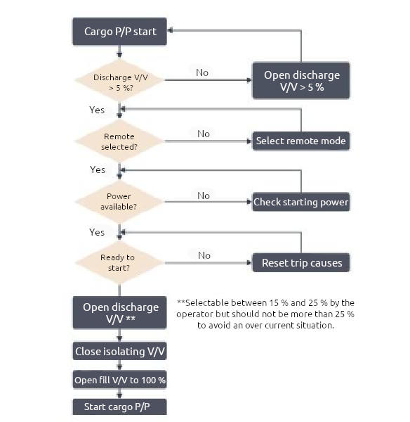
Before starting a typical cargo pump:
- the cargo pump column should be cooled by using a stripping/spray pump;
- check the level of the liquid in the tank is at least at the minimum stated in the operating instructions. The pumps must not be started when the tank is dry as they must be completely submerged in LNG to ensure that the top bearing is cooled;
- fully open the cargo tank filling valve;
- close the branch (isolation) valve;
- select the automatic or manual mode;
- open the pump discharge valve to about 15 %, as starting the pump with the valve fully open will overload the motor;
- start the cargo pump, keeping a close watch on the discharge pressure and the motor current.
At any time during the operation, the current should not exceed the maximum rated current by more than 50 % for more than 2/3 seconds. If the running current after this time is more than 150 % of the maximum rated current, stop the pump immediately and determine the cause of the high current (possible suction blockage).
Read also: Cargo equipment for gas carriers carrying LNG/LPG
When the pump discharge pipe is filled to the discharge valve, a substantial increase in the discharge pressure and a corresponding decrease in current should be observed.
Once the pump is operating normally, adjust the discharge valve to obtain the required flow or pressure. Monitor the pump motor running current, taking care not to exceed the maximum current level.
Note: When the pump is operating correctly, closing the pump discharge valve during operation will raise the head pressure and, consequently, reduce the running current.
Restarting the cargo pumps during normal operations is restricted and depends on the liquid level above the submerged electric motor and the number of starts available within a specified time period. This is because of the lack of liquid flow when (and if) the pump does not prime, caused by an extremely low level of LNG during stripping operations.
Cargo pumps should not be restarted below the manufacturer’s minimum level recommendations. These vary from ship to ship and can be from 1,0 m to as much as 2,4 m.
Normal start up:
- 1st restart: minimum 30 minutes after shut down;
- 2nd restart: 15 minutes after 1st restart.
For liquid level below the motor centre line (approximately 1,5 m liquid in tank), restart after 30 minutes and not more than 2 starts/restarts within one hour (including the initial start).
Pump control
Control of the pump’s flow rate is achieved by adjusting the discharge valve. Opening the discharge valve will increase the flow rate, which in turn increases pump ampere loading.
The ammeter in the starter panel measures the appropriate current. In turn, the IAS calculates pump load in terms of % of full load. In practice, the operator will follow the process sequence and indications on the IAS.
At the start-up of the cargo pump(s), an initial setting is entered for the desired load on the pump(s). This is based on current load, or on back pressure at the Terminal Operations for LNG or LPG Carrier after Arriving in Portship side/terminal interface manifold. A feedback loop provides data back to the IAS, which compares the actual reading(s) with the desired setpoint.
If the current loading/back pressure (dependent on how the system is set up) deviates from the desired setpoint, an “adjustment” signal is sent from the IAS to the controller for the pump(s) discharge valve(s), opening them further, or closing them to re-establish desired values. This allows for automatic control of the load/pressure on the pumps and is known as “cascade mode”.
If the motor load then elevates above the set point, the output of the load controller decreases. This signal reduction is cascaded to the discharge valve controller as a decreased set value, which in turn demands partial closure of the discharge valve until control circuit balance is restored.
The motor load is converted to a percentage value from the current of each pump.
The calculation equation is as follows:
In the event of activation of the various shutdown trips related to the cargo system and the pumps, the cargo pumps will be automatically stopped.
Alarms and resulting actions
Each cargo pump electric motor is protected from the following events:
- ESD activation;
- motor low-current;
- motor over-current;
- phase fail;
- emergency stop;
- low discharge pressure;
- low level.
Typically, the following limits are set:
| Low current | < 45 A for 5 seconds |
| High current | 400 A (motor starter setting) |
| Single phasing | 1 phase lost (motor starter setting) |
| Low insulation | monitored by switchboard |
| Low-low cargo pressure | < 10 mbar |
| High hold/tank differential pressure | 40 mbar |
| ESD low loop pressure | 3,0 bar |
| Low discharge pressure | < 2,0 bar and > 10 seconds |
The main cargo pumps are commonly soft start but can be direct on-line when required, i. e. if the soft start fails. Swing check valves are installed inside the tanks after the cargo pump discharge flange. These valves, along with the soft starting arrangements, assist in the reduction of any excessive liquid hammer that can occur if the pumps are not started in accordance with the steps outlined.
Soft start. Electronic starting sequence, gentle start and gentler on ship’s power plant.
Direct on-line
Direct starting (i. e. press button and pump goes to full starting current immediately).
The power supply to the cargo pump motors comes via cargo switchboards, which are normally arranged in two independent sections (port and starboard). This is to ensure that if one switchboard fails, power is still available to the other pump in the cargo tank(s). These are operated as coupled via a bus-tie connection, or independently.
Each of the cargo switchboards can be supplied by either or both of the main switchboards.
Because of the high electrical load that is imposed on the cargo switchboards by running the main cargo pumps, the number of pumps that can be run is limited by the electrical power management system (start block).
The pumps should be started individually and sequentially, with the pump discharge valve open (approximately 15 %).
If the pump discharge valve position does not open to minimum 5 %, the pump will not start due to a starting interlock.
Cargo pump control system
Local control: operation of the equipment (start and stop) is performed at the cargo switchboard using the local control panel.
Remote control: operation of the equipment (start and stop) is performed from the IAS. Equipment cannot be operated in both local and remote modes at the same time.
Manual control: operation of the equipment is performed manually by the operator from the IAS operator stations (remote mode only).
Automatic control: operation of the equipment is performed by the IAS control function (remote mode only).
The cargo pumps, pipeline system and starters must be designed to minimise liquid hammer during starting, so the cargo pump non-return valves should be installed in the cargo tank immediately above the pump. Frequency controlled or soft starters should be incorporated into the system.
Points to remember:
- never run pumps dry;
- never blow hot air through a discharge line. This may turn the impeller and rotor at high speed in the wrong direction, damaging the bearings;
- never operate the pump above the motor ammeter red line;
- never assume that all electrical interlocks and safety relays will continuously function correctly;
- do not allow seawater, steam or any cleaning agent containing water to come into contact with a pump, its cables or connections;
- always cool down the pump column;
- never start pumps below the recommended liquid level (depth);
- never exceed the number of allowed restarts;
- never restart pumps before the minimum recommended time period has elapsed;
- never run pumps outside the recommended parameters for extended periods.
LNG is electrically non-conductive. Therefore, the submerged cargo pump relies on the flow of liquid through the pump for motor cooling and bearing lubrication. Its location rules out normal in-service maintenance so reliability is an important factor.
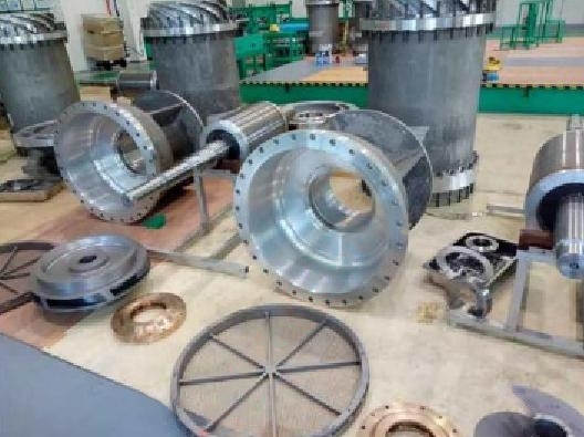
The normal practice is for cargo pumps to be removed “complete” from the cargo tank during refit and then fully overhauled by the manufacturers or an approved specialist company.
The operator must closely monitor cargo pump performance and watch for any apparent decline. Debris in the manifold discharge filters will indicate a problem within the cargo tank. Performance monitoring, by comparison with historical records if necessary, is an important aspect of the associated maintenance.
It is good practice to maintain a log of the insulation readings to earth and between phases for cargo pump motor windings and associated supply cables, as these may be required for inspection purposes. The readings should be taken before every discharge port while following established high voltage safety precautions.