This article deals with the basic chemistry and physics of liquefied gases. The article then discusses the behaviour of gases and continues with a description of how refrigeration and heat transfer principles are applied on board liquefied gas carriers.
- The Chemistry of Liquefied Gases
- Atoms, Molecules and Chemical Bonds
- The Hydrocarbon Series
- Chemical Formulae and the IUPAC Naming System
- Saturated and Unsaturated Hydrocarbon
- The Chemical Gases
- Chemical Reactivity and Compatibility
- Reactivity with Construction Materials
- Reactivity with other Cargoes
- Self-reaction
- Reactive Properties
- Formation of Polymers or Dimers
- Reaction with Water – Hydrate Formation
- Reaction with Air
- Combustion
- Flammability/flammable Range
- Suppression of Flammability
- Inert Gas and Nitrogen
- The Use of Inert Gas
- The Chemical Compatibility of Cargoes with Inert Gas or Nitrogen
- The Physical Properties of Liquefied Gases and their States of Matter
- Temperature, Heat Energy and Phase Change
- Specific Heat Enthalpy and Antropy
- Phase Change – a Summary
- Saturated Vapour Pressure (SVP)
- Liquid and Vapour Densities
- Liquid to Vapour Volume Ratios
- Spillage of Cargo Liquid
- Viscosity of liquid cargoes
Specific problems that may be encountered, such as hydrate formation, polymerisation and stress corrosion cracking, are also discussed. Further details on these particular issues can be found in the publications and references listed in the Appendix.
The Chemistry of Liquefied Gases
Atoms, Molecules and Chemical Bonds
To understand how liquefied gases behave we need to understand their structure. Everything is made of atoms and each atom consists of electrons, protons and neutrons. The arrangement resembles a miniature solar system and the protons and neutrons form the core (or nucleus) of each atom, with the electrons orbiting around them.
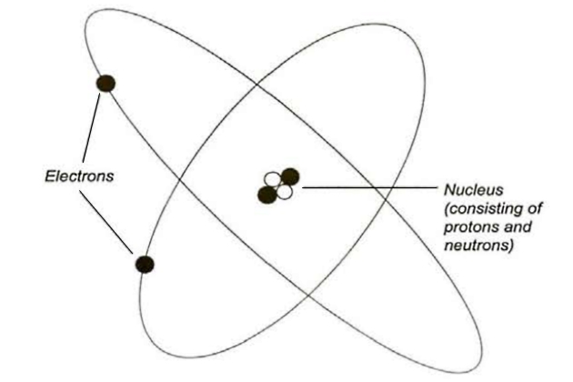
The protons and neutrons have approximately equal mass, which is designated as 1 atomic mass unit. These particles are much heavier than the electrons, which have virtually no mass at all. The electrons do, however, have a negative electrical charge, which is equal and opposite to the positive charge of the proton. Neutrons have no electrical charge whatsoever.
Each atom must have an equal number of electrons and protons to maintain electrical balance while the nucleus contains sufficient neutrons to provide a stable structure.
The difference between the elements is the number of electrons or protons in the atoms. For example, the simplest atom comprises just 1 electron circulating around 1 proton, which is the element we know as hydrogen. Therefore, the total mass of each hydrogen atom is 1 atomic unit. The next simplest atom comprises 2 electrons circulating around 2 protons, but this element (helium) requires 2 neutrons in the nucleus for stability. So each helium atom has an atomic mass of 4 atomic units.
Each next heaviest element in the series is made by adding 1 electron and 1 proton to each atom of the previous element, plus an appropriate number of neutrons.
When the elements are written in order of increasing atomic mass, similarities in behaviour of different elements can be noticed and can be grouped together in families. These groupings are collectively known as the “Periodic Table of elements”.
The most common elements that will be encountered in the liquefied gas industry are:
| Table 1. Common elements | ||||
|---|---|---|---|---|
| Element | Symbol | Atomic number | Atomic mass | Naturally occurs as |
| Hydrogen | H | 1 | 1,0 | H2 |
| Carbon | C | 6 | 12,0 | Cn |
| Nitrogen | N | 7 | 14,0 | N2 |
| Oxygen | O | 8 | 16,0 | O2 |
| Chlorine | Cl | 17 | 35,5 | Cl2 |
| Sulphur | S | 16 | 32,1 | S |
| (* In nature, carbon exists in several forms) | ||||
Many elements can have atoms with different numbers of neutrons in the nucleus but still with the same number of protons and electrons. These are called “isotopes” and are referred to by their atomic mass. For example, there is an isotope of carbon with 2 extra neutrons called carbon 14, but carbon 12 is by far the most common isotope.
The fact that an element can contain different isotopes can result in the atomic mass not being a whole number. Chlorine, for example, has an atomic mass of 35,5 because 3 out of every 4 atoms have a mass of 35 while the remainder have a mass of 37 due to the presence of 2 extra neutrons in the nucleus.
When atoms of different types join together to form compounds, it is the electrons that interact and form the bonds that make up the new building blocks of the compounds, known as molecules. Each molecule is the smallest part of the compound that displays all the chemical properties of that material.
When atoms join together, the bond is formed by the electrons shared between those atoms. The number and type of bond that each different atom can form depends on the number of electrons available and other aspects of the atomic structure. The atomic nuclei, ie protons and neutrons, are not involved in chemical bonding.
It is important to understand that the number of electrons available for bonding is not the same as the total number of electrons in the atom. A good, and relevant, example is carbon, where the atomic number of 6 may lead us to believe it would have 6 bonds, but in actual fact only the 4 in the outer shell, which is known as the “valence shell”, are actually available.
Carbon is one of the most interesting elements as it can form a number of different compounds (where atoms of carbon are joined to each other rather than to anything else) depending on the temperature and pressure applied during the formation of the material. Coal, graphite and diamonds are examples of different materials made up from virtually nothing else but carbon.
All life forms are based on the unique property of carbon to form very long chains of molecules and the study of carbon-based molecules is known as “organic chemistry”. In particular, carbon forms very strong bonds with other carbon atoms and also with hydrogen atoms.
When a molecule is formed, a simple chemical formula shows the ratio between the different atoms, known as the molecular formula.
It is the molecules made from the combination of carbon and hydrogen atoms that are most relevant to the liquefied gas industry. These are known as “hydrocarbons”.
The Hydrocarbon Series
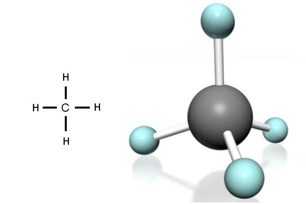
Each carbon atom can form 4 bonds. The simplest compound of carbon and hydrogen is methane, which has the formula CH4. This means that each carbon atom “hook” (electron) has attached to a hydrogen atom. In the methane molecule the bonds between the carbon and hydrogen atoms are very strong, so this compound is very stable. This stability is important as it means the molecule will stay that way in most pressure and temperature conditions. The molecule is in the shape of a pyramid, with the bonds facing towards the corners.
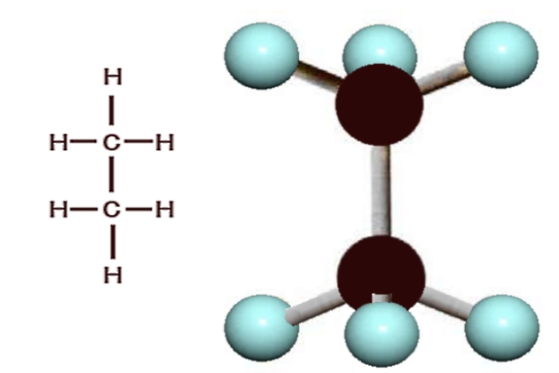
Carbon can form long molecular chains with itself, and the next compound of carbon, which is also naturally occurring, contains 2 carbon atoms and 6 hydrogen atoms. This gas, which is called “ethane“, is represented by the molecular formula C2H6.
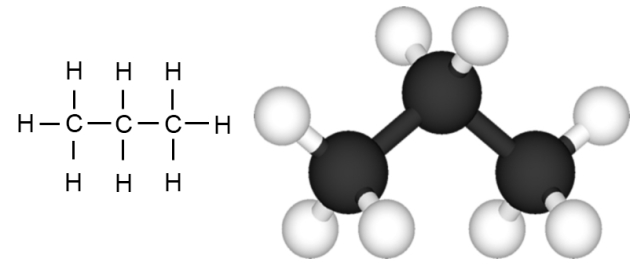
Propane, which is the next gas in the hydrocarbon series, contains 3 carbon atoms joined together in a chain, with the remaining bonds being made with hydrogen atoms. It is represented by the molecular formula C3H8.
Looking at these molecular formulae so far, it can be seen that each carbon atom in the chain forms 2 bonds with hydrogen while the 2 carbon atoms at the end of the chain both form bonds with 3 hydrogen atoms. This means we can use the general formula of CnH(2n+2) for the simple hydrocarbons.
The next member of the hydrocarbon series, which we can predict to be C4H10, is called “butane“. This molecule is the first in the series that has two alternative structures for the central carbon chain.
Butane can be visualised as being made by adding one extra carbon atom plus 2 hydrogen atoms to a propane molecule.
This fourth carbon can be added at either end of the existing molecule, making a straight chain as shown in figure 5, or it can join the middle carbon atom to form a branched chain as shown in figure 6.
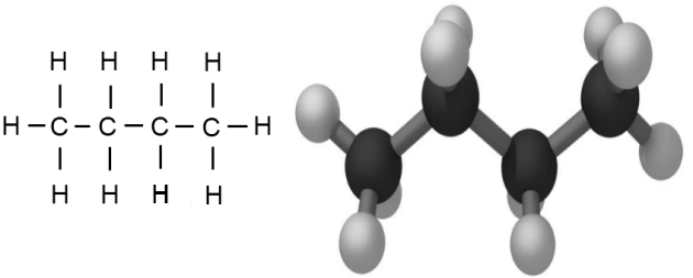
Both alternatives have the same molecular formula but have different structures. This property is known as “isomerism”.
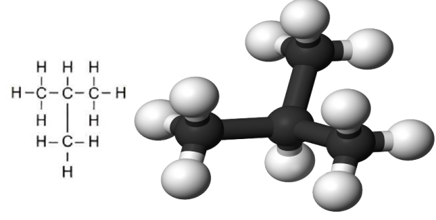
The two different forms of C4H10 are known as “normal butane” and “iso-butane“, which is sometimes abbreviated to “n-butane” and “i-butane“. They have very similar chemical properties but have different physical characteristics, the most relevant of which, due to the difference in molecular structure, is the temperature at which they evaporate.
Commercial butane cargoes are usually mixtures of normal and iso-butane, with the normal composition range usually about 65 % n-butane to 35 % i-butane. However, the isomers may be separated and shipped independently as feedstock for specific chemical processes.
Hydrocarbons with up to 4 carbon atoms are gases at normal ambient temperatures and pressures and so have to be liquefied for bulk shipment. Hydrocarbons with 5 to 20 carbon atoms are liquids and those with 20+ carbon atoms are solids at ambient conditions. Pentane, which has the formula C5H12, is a volatile liquid and may be carried onboard gas carriers in warm ambients.
Carbon atoms have the capability to not only form single bonds with adjacent carbon atoms, shown as ‘C – C’ in figures 3 to 6, but they can also form double bonds, shown as ‘C = C’. This can be pictured as being formed by the alignment of the edges of two adjacent carbon pyramid layouts (see point “Saturated and unsaturated hydrocarbon” below). The ‘C = C’ double bond is shorter than the single bond, which means the electrons are spread out less than compared to a single bond, and this makes the double bond more reactive and less stable. It is also possible for adjacent carbon atoms to form triple bonds, which are even more reactive.
Carbon also forms bonds with other elements, such as oxygen, which in turn also bond strongly with hydrogen. The compound formed by one atom each of hydrogen and oxygen is known as the “hydroxyl group” and is written as “OH“. When this functional group is combined with a hydrocarbon it forms a molecule of the family known as “alcohols” (such as, methanol and ethanol).
Carbon also forms compounds with sulphur, many of which have a strong and unpleasant smell. In the liquefied gas industry the best known is ethyl mercaptan (CH3CH2SH or, more commonly, C2H6S), which is used to odourise hydrocarbons such as methane, propane and butane before they are distributed via gas mains to the general public. The odourant gives an early warning of any potentially hazardous gas leak and is essential for public safety as hydrocarbons are virtually odourless when pure. However, sulphur, which is one of the chemical constituents of ethyl mercaptan, can react strongly with copper so there are usually limits on sulphur content in cargoes such as liquefied petroleum gas (LPG), where the equipment used may contain a lot of copper based material.
The range of compounds that can be created using carbon and various other elements is very broad, so a system of naming has been developed to enable all of these chemicals to be described clearly.
Chemical Formulae and the IUPAC Naming System
The International Union of Pure and Applied Chemistry (IUPAC) has a systematic method for naming organic chemicals so that a name can be assigned to indicate the structure of the molecule clearly and unambiguously.
It names the molecules, starting from the main hydrocarbon chain in the structure, and includes single and double bonds. Hydrocarbon side chains and functional groups, such as the OH groups, are then identified. Next, the carbon atoms in the main chain are numbered to give the lowest number to the carbon atom with the functional group or multiple bond attached. This numbering is only important for non-symmetrical molecules.
When the main chain carbon atoms have been numbered, the name of the molecule is written to include the constituent molecules, any side chains or functional groups and any multiple bonds.
In molecules with larger numbers of carbon atoms, branches off the main carbon chain are referred to as “iso“, while the straight chain arrangement with the same formula is known as “normal“.
In the liquefied gas industry the only points where structure becomes significant is for molecules containing 4 or more carbon atoms, the most common of which are the cargoes related to butane.
Alternative names that are used for the same compound are called synonyms. The more complex molecules generally have more synonyms than simpler compounds.
Saturated and Unsaturated Hydrocarbon
In chemical terminology a molecule that only has single bonds is called “saturated”, while any molecule that has one or more double bond in the structure is referred to as “unsaturated”.
Carbon can form either single, double or even triple bonds with itself and the simplest molecules with single, double and triple bonds are those with two carbon atoms. These are ethane (C3H6), ethylene (C2H4) and acetylene (C2H2) (the IUPAC names are ethane, ethene and ethyne).
Figure 7 shows that for saturated hydrocarbon molecules, the proportion of carbon and hydrogen atom molecules can be described by the general formula CnH2n+2. Methane (CH4), ethane (C2H6), propane (C3H8) and butane (C4H10) are all common examples of saturated hydrocarbons.
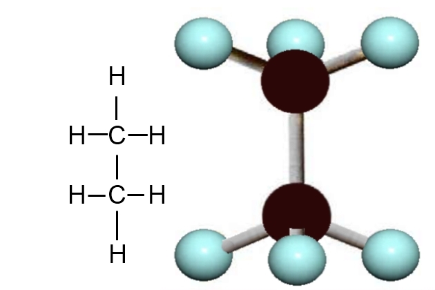
The formation of a double bond between two adjacent carbon atoms in a hydrocarbon chain means the replacement of two potential carbon and hydrogen bonds. Therefore, hydrocarbon molecules with only one double bond have the general formula CnH2n. Ethylene (C2H) propylene (C3H6) and butylene (C4H8) are all common examples of unsaturated hydrocarbons containing one double bond.
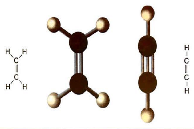
Hydrocarbons containing triple bonds are generally too reactive for transportation as liquids, but one common cargo that contains two double bonds is butadiene (C4H6).
The alternative structures of butylene and butadiene give rise to a number of synonyms, shown by the IUPAC descriptions in table 2.
| Table 2. IUPAC names and synonyms | |||
|---|---|---|---|
| Common name | IUPAC name | Chemical formula | Synonyms |
| Methane | Methane | CH4 | Fire damp, marsh gas, natural gas, LNG |
| Ethane | Ethane | C2H6 | Bimethyl, dimethyl, methyl methane |
| Propane | Propane | C3H8 | LPG |
| n-Butane | Butane | C4H10 | Normal-butane, LPG |
| i-Butane | 2-Methyl propane | C4H10 | Iso-butane, 2-methylpropane; LPG |
| Ethylene | Ethene | C2H4 | Ethene |
| Propylene | Propene | C3H6 | Propene |
| ∞-Butylene | But-1-ene | C4H8 | Ethyl ethylene |
| β-Butylene | But-2-ene | C4H8 | But-2-ene, dimethyl ethylene; pseudo butylene |
| γ-Butylene | 2-Methyl-prop-2-ene | C4H8 | Isobutene |
| Butadiene | 1,3 Butadiene | C4H6 | b. d., bivinyl, butadiene 1-3, divinyl, biethylene, erythrene, vinyl ethylene |
| Isoprene | 2-Methyl-1,3 butadiene | C5H8 | 3-methyl-1,3 butadiene 2-methylbutadiene-1,3 |
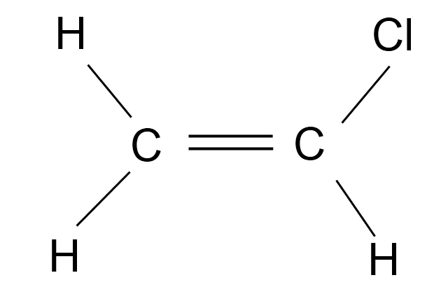
| Vinyl chloride | Chloro-ethene | C2H3Cl | Chloroethylene, VCM, vinyl chloride monomer |
| Ethylene oxide | Oxirane | C2H4O | Dimethylene oxide, EO, 1,2 epoxyethane, epoxyethane, oxacyclopropane |
| Propylene oxide | 1, 2 Epoxy propane | C3H6O | Epoxy propane, methyl oxirane, propene oxide, propylene epoxide, 1,2-propylene oxide, methyl oxirane, 1,2-epoxypropane, methyl ethylene oxide, methylethylene oxide, PO, propOx |
| Ammonia | Ammonia | NH3 | Anhydrous ammonia, liquid ammonia |
| Hydrogen | Molecular hydrogen | H2 | none |
Section “Atoms, molecules and chemical bonds” showed the alternative structures for butane are called normal-butane or iso-butane. However, from the IUPAC table we also see the name “2-methyl propane” is also used.
Structurally, a single bond can be visualised as being like an axle, around which the atoms can rotate. However, when a double bond is formed, the ability to rotate around that bond is lost and this means there may be structural differences between the opposite sides of a double bond.
Taking butadiene (C4H6) as an example, the variation in the bonding will give different names to the product, so where the double bonds are adjacent it is known as 1,2 butadiene, but if they are separated they are called 1,3 butadiene.
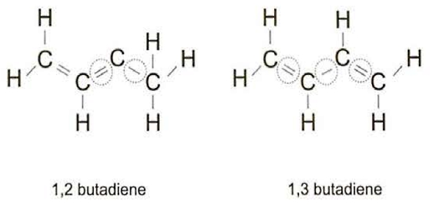
The proportions of the different “types” within the butadiene cargo are usually shown in the cargo quality certificate. The exact proportions may vary with the cargo temperature but, under normal transport conditions the “1,2” isomer will comprise less than 1 % of the cargo and the “1,3” isomer will make up over 95 % of the total cargo.
As the number of carbon atoms increases the number of structural permutations multiplies.
Cargoes with 5 carbon atoms, such as pentane or pentene, are liquid at cooler ambient conditions but have a high vapour pressure (see point “Saturated vapour pressure (SVP) below”), so may be shipped on gas carriers in warm ambients. They are always carried as mixed isomers. The only other “C5” cargo that is seen in the gas trades is “isoprene” (2 or 3-methyl-1,3 butadiene). As the name indicates, the cargo is a mixture of isomers derived from butadiene and it is mainly used to make synthetic rubber.
The Chemical Gases
Some non-hydrocorbon cargoes are carried on gas carriers, usually referred to as chemical gases, and their proprties vary considerably. As these cargoes can be toxic, appropriate personal protectiv equipment (PPE) will be used when handling them and information on what PPE is required will commonly be found on the safety data sheet (SDS) for that specific cargo.
Ammonia (NH3)
This is a colourless alkaline liquid with a pungent odour that is highly toxic. Ammonia is a very common cargo as it is used widely in the fertiliser industry.
Ammonia is extremely soluble in water and will be absorbed rapidly and exothermically to produce a strong alkaline solution of ammonium hydroxide. One volume of water is capable of absorbing up to 1,000 volumes of ammonia vapour. This fact can be used to reduce gas concentrations during gas-freeing, or if there is an accidental spillage for example.
Ammonia is highly reactive. If can form explosive compounds with mercury, chlorine, iodine, bromine, calcium, silver oxide and silver hypochlorite. The alkaline nature of ammonia vapour/air mixtures can cause stress corrosion cracking (SCC) in metals, especially in cargo systems (see Reference 2.5).
The precautions required by the IGC Code to reduce the risk of SCC are:
- Do not use steel with a nickel content above 5 % in a cargo system;
- keep the dissolved oxygen content in the cargo below 2,5 ppm (w/w1) by minimising the O2 content of the tank atmosphere before ammonia is first introduced;
- fine grain carbon-manganese steels used for tank construction or cargo piping/containment should have a minimum yield strength not exceeding 355 N/mm2 and an actual yield strength not exceeding 440 N/mm2. In addition, lower strength material, with a lower minimum tensile strength not exceeding 410 N/mm2 yield strength, should be used;
- thermal stress relief is required for tank shell welds after construction;
- the cargo temperature should be maintained below minus 20 °C (-20 °C) (but preferably close to minus 33 °C (-33 °C));
- at least 0,1 % water (w/w) is added to the ammonia; up to 0,2 % (w/w) is acceptable.
The detailed requirements for carrying this cargo are set out in the IGC Code and are discussed in article “Features of cargo delivery LNG/LPG carriersLPG/NH3 carriers“.
Vinyl chloride monomer (VCM)
This is a colourless liquid with a characteristic sweet odour. It is used widely in the plastics industry to make PVC. For this reason, the cargo is often called vinyl chloride monomer or VCM.
The vapours of VCM are both toxic and flammable.
Steels are suitable for VCM service, but this cargo is chemically incompatible with aluminium alloys, copper, silver, mercury and magnesium.
The detailed requirements for carrying this cargo are set out in the IGC Code.
Ethylene oxide (EO) and propylene oxide (PO)
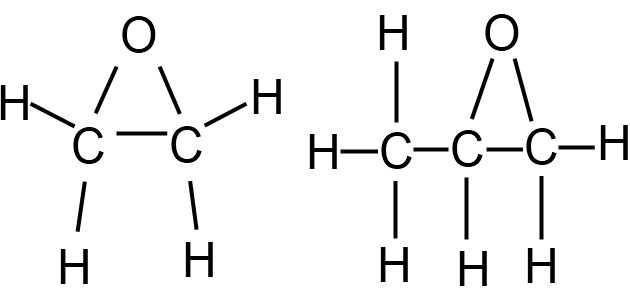
These are highly reactive, colourless liquids with an ether-like odour that are used to make common industrial chemicals such as glycols. EO is more sensitive than PO and is rarely carried in bulk as this cargo requires a Type 1G ship. Cargoes of PO and cargo mixtures of EO and PO containing less than 30 % EO are more common; these cargoes can generally be carried on Type 2C chemical tankers or Type 2G gas carriers (see article “Liquefied Gas Carrier TypesSurvival Capability“).
EO and PO cargoes are self-reactive, particularly in the presence of air or materials that can catalyse the reaction. For this reason the IGC Code specifies that cargoes of PO and EO/PO mixtures are required to be acetylene-free for shipment.
Both cargoes are flammable and toxic. The flammability hazard is increased because these products contain oxygen that can assist the combustion process. Furthermore, if the products decompose at ambient conditions, that process creates two gases and the sudden volume expansion may be explosive.
The detailed requirements for carrying these cargoes are set out in the IGC Code.
Chlorine
This is a highly reactive yellow liquid that gives off a green vapour that is pungent, irritating and highly toxic. Chlorine is widely used in the chemical process industry because of its reactivity, but it is often made locally to minimise transportation. If carried by sea, it is aboard highly specialised ships or barges.
When dry, chlorine is generally compatible with mild steel, stainless steel, monel and copper. However, chlorine is difficult to contain if it is moist as it is soluble and forms highly corrosive acids. Chlorine is also very soluble in sodium hydroxide solution (commonly known as “caustic soda”), which can be used to absorb chlorine vapour.
Chlorine is non-flammable, but it can support combustion of other flammable materials in much the same way as oxygen does. Chlorine can react dangerously with all other liquefied gas cargoes.
Chemical Reactivity and Compatibility
Reactivity with Construction Materials
Table 3 shows the chemical reactivity of the main liquefied gas cargoes with the construction materials that may be used in the cargo system (which may come into contact with the cargo). Further information will be found in the IGC Code.
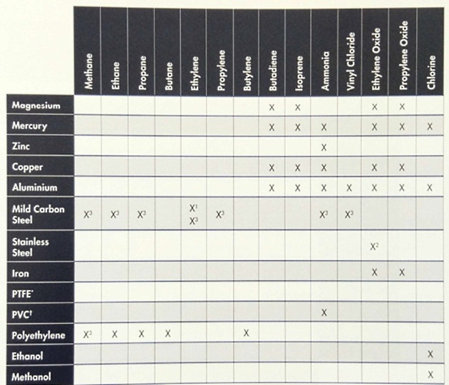
Notes: For further details on chemical reactivity, refer to the data sheets in Reference 2.1 and the IGC Code.
- Stainless steel containing 5 % nickel is the usual containment material For ethylene.
- Refer to IGC Code, Chapter 17 – Special Requirements.
- Risk of brittle fracture with fully-refrigerated cargo.
- *PTFE: polytetrafluoroethylene (jointing material)
- ┼PVC: polyvinyl chloride (electric cable insulation)
Reactivity with other Cargoes
Table 4 summarises the chemical reactivity between the main cargoes.
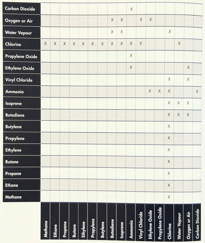
Confirmation should always be sought from shippers when changing from one grade to another.
Self-reaction
Reactive Properties
Formation of Polymers or Dimers
Polymerisation is a chemical reaction, used widely in the chemicals industry, where many molecules are joined together to make a new product. The process usually involves breaking one or more double bonds in the original molecules so that they form new single bonds with other molecules.
If a single molecule (a monomer) combines with one other molecule of the same type, the substance formed is called a dimer. If the process continues until a long-chain molecule is formed, the material formed is known as a polymer. Polymer molecules may contain many thousands of the individual monomer groups.
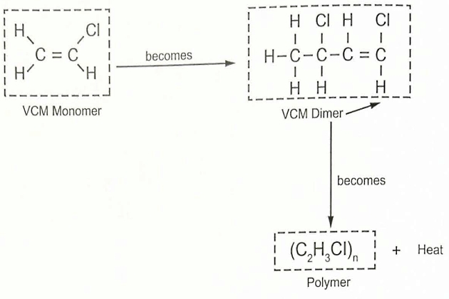
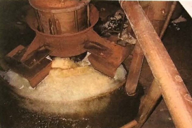
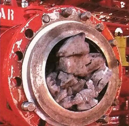
A good example is VCM (C2H3Cl), which is a highly reactive molecule that is a gas at standard temperature and pressure (STP), which is defined by IUPAC as a temperature of 273,15 K (0 °C) and an absolute pressure of exactly 1 00,000 Pa (1 bara). Its high reactivity means that in light or heat the process of polymerisation will occur, and this is illustrated in figure 12. The reaction can be rapid and will itself generate a significant amount of heat. While the process may be initiated spontaneously, it can also be catalysed by the presence of oxygen or other impurities, or by heat transfer during cargo operations (see also article “Features of cargo delivery LNG/LPG carriersCargo temperature and pressure control” and “Features of cargo delivery LNG/LPG carriersOperation of the reliquefaction plant on refrigerated LPG carriers“). If polymerisation does occur, the cargo will become warmer and more viscous and a solid unpumpable polymer may be formed.
It is also possible to polymerise different monomers together to make a polymer with different properties. An example of this is the co-polymerisation of butadiene and isoprene to produce a type of synthetic rubber.
Many of the unsaturated liquefied gases can be made into polymers because of the double bond in their molecular structure (which means they are less stable). However, in many cases, polymerisation requires high temperatures, high pressures and the presence of a catalyst.
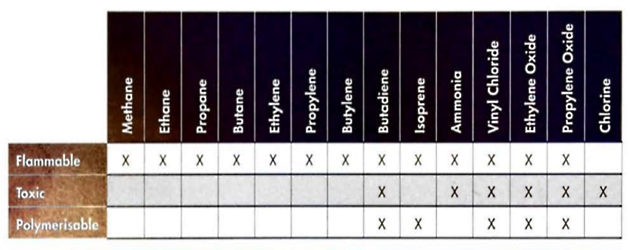
Therefore, potential problems due to polymerisation of the cargo may only really be of concern for:
- butadiene
- isoprene
- vinyl chloride
- ethylene oxide
- propylene oxide.
The risk of polymerisation occurring during the voyage may be reduced significantly by adding an inhibitor to the cargo. This is mandatory for butadiene under the IGC Code requirements and, under certain loading conditions, it may also apply to VCM. However, any inhibitor will be consumed gradually during the voyage until a point is reached when it is no longer effective.
If an inhibitor is required for the cargo, an inhibitor certificate should be provided in accordance with the IGC Code. This certificate should provide the information shown in figure 14.
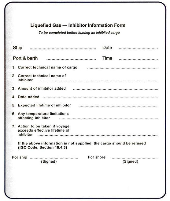
It is also important that the quantity of inhibitor required for effective inhibition, and any toxic properties it may have, are advised.
Inhibitors can be toxic. The inhibitors used most commonly are tetrahydroquinone (THQ) for VCM and tertiary butyl catechol (TBC) for butadiene. Particular care should be taken when handling inhibitors and cargoes with inhibitor added. The SDS for the particular inhibitor should be provided in addition to the inhibitor information form.
The difference between the vapour pressures (see point “Saturated vapour pressure (SVP)”) of the cargo and its inhibitor has an important implication on the behaviour of the inhibitor.
Increased polymerisation rates may occur in the vapour space and traces of low density polymer have occasionally been seen in these areas. Potential problems can be minimised by controlling the temperatures in the reliquefaction circuit and in the cargo tank vapour space.
In the case of butadiene, the TBC is added primarily as an oxygen scavenger, to remove any oxygen dissolved in the cargo, as this could act as a catalyst for polymerisation. In the absence of oxygen it acts as an inhibitor to only a limited extent.
In other cases there may be no effective inhibitor. Potential polymerisation is controlled by keeping the cargo cool because chemical reactions progress at a slower rate when the temperature is reduced.
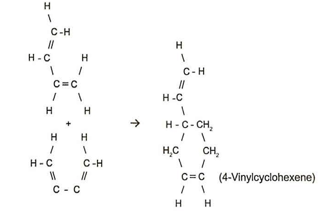
The first stage of any polymerisation reaction, dimerisation, is where two monomers join together. This is a particular concern with butadiene cargoes. The problem is similar to polymerisation but the reaction is more difficult to control as the dimer is itself a stable chemical.
Dimerisation of butadiene cannot be stopped by inhibitors, but can only be slowed down by keeping the cargo as cool as possible. Below 4°( the dimerisation reaction slows significantly. Cargo quality is maintained if it is possible to cool cargo to below this temperature, especially during longer voyages.
Not all unsaturated cargoes are self-reactive. For example, ethylene and propylene do not have this problem and propylene is sufficiently stable that it can be used as a refrigerant.
Reaction with Water – Hydrate Formation
If any free water remains in the cargo system, it will collect in the lowest points as water has a higher density than the cargo. If the cargo system is cooled below 0 °C, any free water in the system will freeze.
There is an alternative reaction between most hydrocarbons and water that causes solid cage-like molecules, known as “hydrates”, to form at temperatures above 0 °C. The conditions for the formation of hydrates depend on the hydrocarbon and the pressure, but can be up to 6 °C for propane and butane (see Reference 2.6).
Hydrates are white crystalline solids that will block filters, spray nozzles and reliquefaction condenser level control valves. They can also block or cause damage to cargo pumps.
If problems are experienced with either frozen water or hydrate formation, it may be permitted for some LPG cargoes to add a hydrate inhibitor, such as methanol or ethanol, at suitable points in the system. Cargoes such as ethylene are usually carried at temperatures below the freezing points of hydrate inhibitors.
Nothing should usually be added to any cargo without the consent of both the ship operator and the shipper, as many cargoes used as chemical feedstock would be regarded as “off spec” by the addition of any such hydrate inhibitor.
In addition to the quality issues, it must also be noted that some countries ban the use of methanol because it is highly toxic. It is essential to recognise the risks of handling any hydrate inhibitor.
With any water remaining in the cargo system having the potential to cause problems, especially if the cargo is refrigerated, it is important to pay close attention to the dew point of the tank atmosphere when the system is being prepared for loading.
The moisture that can form ice or hydrates may be present in the cargo itself as an impurity. This is most common with LPG. In addition, moisture may be extracted from rust on cargo tank bulkheads during a cargo grade change.
Suggested reading: Fuelling the Future – Powering the LNG Carriers
While water is virtually insoluble in most liquid hydrocarbon cargoes, the fact that it is significantly more soluble in hydrocarbon vapour than in the liquid can cause operational problems.
As an example, propane liquid at 10 °C may contain approximately 65 ppm of water, while propane vapour at the same temperature may contain about 700 ppm of moisture. Furthermore, if the propane is refrigerated to about minus 40 °C (-40 °C), the water carrying capacity of the cargo is reduced to about 2 ppm in the liquid phase and around 65 ppm in the vapour phase.
Therefore, if a liquid propane cargo was loaded at 10 °C and was saturated with water before transfer, significant amounts of water would be released if it was cooled down to atmospheric pressure. The moisture would first migrate to the vapour phase and condense out in the reliquefaction plant, causing blockages. The freezing point of LPG cargoes is often checked as part of the quality control system to ensure such problems do not arise.
Any water dissolved in butadiene also behaves in a similar way, which is shown in figure 18. If water saturated butadiene is cooled, the water carrying capacity of the cargo decreases significantly and water will separate out as droplets that settle to the bottom of the tank.
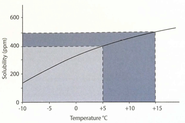
If water saturated butadiene is cooled from 15 °C to 5 °C, approximately 100 ppm of free water separates out. On this basis, as much as 0,1 m3 of free water could need to be drained from the bottom of a 1,600 m3 cargo tank. If the cargo was further cooled to below 0 °C, the depth of the water layer would increase and it would freeze.
Hydrate inhibitors, such as methanol or ethanol, should never be added to an already inhibited cargo as these chemicals interfere with the inhibition mechanism. Expert advice should always be sought to confirm the appropriate action.
Reaction with Air
Combustion
Combustion is a special type of chemical reaction where, for example, a flammable hydrocarbon vapour combines with oxygen to produce CO2 and water. The reaction requires the mixture of vapour and O2 to be within the flammable range and a source of ignition is needed to start the process. Heat is usually given out during the combustion process, which continues the reaction.
Methane combustion can be shown at a molecular level:
What we can see here is that 2 molecules of oxygen link with one of methane and split to create O2, water vapour and heat (energy from the molecular activity).
Propone combustion looks like this:
The heat given out when a gas burns can be stated in two different ways. The “higher heating value” calculates the energy released assuming the combustion products are brought bock to the same conditions as the original fuel, meaning that the water vapour in the exhaust is condensed. By contrast, the “lower heating value” measures the heat released without condensing any moisture from the combustion products. The difference is usually around 10 %, due to the significant latent heat contained in the water vapour in the exhaust (see point “Phase change – a summary” below).
Flammability/flammable Range
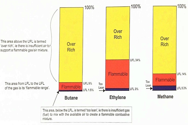
A flammable gas will only burn in air when the mixture is within a certain range, known as the “flammable range”, which in turn depends on the type of gas involved.
If the gas/air mixture does not contain a certain minimum proportion of gas, there will not be sufficient fuel to create combustion and the mixture is said to be “too lean”. If the gas/air mixture contains excessive fuel, the mixture cannot burn and is described as “over rich”·
The range of compositions between “too lean” and “over rich” is known as the “flammable range“. This is the range of mixtures that will actually burn.
Most of the common liquefied gas cargoes are flammable, but their flammable ranges vary. The flammable ranges for butane, ethylene and methane are illustrated in figure 19.
Flash point
The flash point of a liquid is the lowest temperature at which that liquid gives off sufficient vapour, when mixed with air, to form a flammable mixture.
Liquefied gases have high vapour pressures and, therefore, have relatively low flash points (see table 6).
| Table 6. Ignition properties for liquefied gases | |||
|---|---|---|---|
| Liquefied gas | Flash point (°C) | Flammable range (percent by vol. in air) | Auto-ignition temperature (°C) |
| Methan | minus 175 (-175) | 5,3 to 14,0 | 595 |
| Ethane | minus 125 (-125) | 3,0 to 12,5 | 510 |
| Propane | minus 105 (-105) | 2,1 to 9,5 | 468 |
| n-Butane | minus 60 (-60) | ,15 to 9,0 | 365 |
| i-Butane | minus 76 (-76) | 1,5 to 9,0 | 500 |
| Ethylene | minus 150 (-150) | 3,0 to 34,0 | 453 |
| Propylene | minus 108 (-108) | 2,0 to 11,1 | 453 |
| ∞-Butylene | minus 80 (-80) | 1,6 to 10,0 | 440 |
| β-Butylene | minus 72 (-72) | 1,6 to 10,0 | 465 |
| Butadiene | minus 60 (-60) | 1,1 to 12,5 | 418 |
| Isoprene | minus 50 (-50) | 1,5 to 9,7 | 220 |
| Vinyl chloride | minus 78 (-78) | 4,0 to 33,0 | 472 |
| Ethylene oxide | minus 18 (-18) | 3,0 to 100 | 429 |
| Propylene oxide | minus 37 (-37) | 2,1 to 38,5 | 465 |
| Ammonia | minus 54 (-57) | 14 to 28,0 | 650 |
| Chlorine | Non-flammable | ||
Auto-ignition temperature
The auto-ignition temperature of a gas is the temperature to which its vapour-in-air mixture must be heated before it will ignite spontaneously, without the help of any external flame or ignition source.
Flash point and auto-ignition temperature are sometimes confused.
There is no direct correlation between the auto-ignition temperature and the vapour pressure or Flash Point – Definition and Pronunciationflash point of the gas. Therefore, it is the flash point that is used for the flammability classification of gases, rather than the auto-ignition temperature, as the most likely ignition sources are external flames or sparks.
However, the auto-ignition temperature becomes important to consider in the event of gas release onto adjacent steam pipes or other hot surfaces, so this information is also provided in table 6.
Ignition energy
Flammable mixtures can be ignited by sources such as naked flames, electric arcs, metal to metal impact or sparks. The minimum ignition energy for hydrocarbon vapours is very low, typically less than one millijoule (mJ), especially if the vapour concentration is in the middle of the flammable range. This is a level of energy exceeded substantially by any visible flame, by most electric circuit sparks or by electrostatic discharges down to the lowest level detectable by human contact.
Once flammable, liquefied natural gas (LNG) vapours ignite easily. The minimum ignition energy of LNG vapours is approximately 0,29 mJ.
Ammonia requires a much higher ignition energy (of approximately 600 mJ). In addition, its lower flammable limit (LFL) is much higher than humans can tolerate in air. Even if it was ignited, the heat produced is not sufficient to keep the combustion going. For these reasons, ammonia is classified as “non-flammable” under the IGC Code, although the ignition of ammonia vapour cannot be discounted completely.
Static electricity
When liquids flow through pipes quickly, the surface contact can cause the loss of outer electrons from the liquid surface, which in turn causes a static electrical charge in the product. Most liquefied gases are poor conductors of electricity, so any static charge may accumulate and create a significant voltage. This accumulated charge may be on the order of millijoules, but still sufficient to ignite a flammable hydrocarbon gas.
By comparison, static electricity discharged when hair is brushed is in excess of 10 mJ.
The risk from static electricity can be minimised by avoiding flammable mixtures inside the cargo system at all times and by the use of electrical bonding across joints in the ship’s pipework to ensure there is an earth path for the current. The “insulation flange” between the ship and shore system is usually designed to prevent low voltage current flow, while allowing any higher voltage static charges to pass safely to earth. A further discussion into the use of insulation flanges can be found in the SIGTTO publication, “A Justification into the Use of Insulation Flanges (and Electrically Discontinuous Hoses) at the Ship/Shore and Ship/ Ship Interface” (Reference 2.7).
Flammability within vapour clouds
If a liquefied gas was spilled in the open air the rapid evaporation of the liquid would produce a vapour cloud that would, in turn, disperse downwind.
It is important to understand that this vapour cloud is flammable only within a part of its volume. This is illustrated in figure 20.
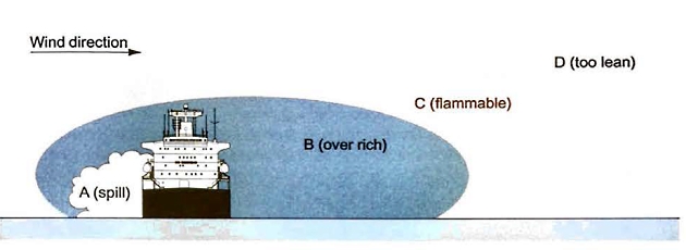
If the spill occurs at point “A“, the region “B“, immediately adjacent to the spill, is non-flammable because it is over rich, ie the oxygen concentration is too low to be flammable. Further downwind, region “D” is also non-flammable because it contains too little vapour to be flammable (it is too lean). The flammable zone is in region “C“.
Cargo tank vent outlets with effective flame screens (or, alternatively, approved safety heads) are to be provided for certain chemical gas cargoes listed in the IGC Code (References 1.1 and 1.2) and the IBC Code (Reference 1.12). The IGC Code further instructs that flame screens should be removed and replaced by suitable protection screens, as defined in the IGC Code, when not required. Attention should be paid to the possibility of the blockage of flame screens and vent heads by, for example, the freezing of cargo vapour or by icing up in adverse weather conditions.
Chemical cargoes have very low vapour pressures so, if a relief valve lifted, there is a potential risk of flammable mixtures existing in the vent mast for some time. Therefore, there is a serious risk of a flame entering the cargo tank in the event of a mast being struck by lightning, if flame screens are not fitted for certain chemical cargoes listed in the IGC Code.
Further discussion of the hazards associated with the flammability of liquefied gases will be found in article “Basics of safety on gas carriersPrincipal Hazards“.
Suppression of Flammability
If the atmosphere containing flammable gas has a higher oxygen concentration compared with that in normal air, the flammable range (see point “Flammability/flammable range” above) is extended. Flammable ranges in air and in oxygen are shown in table 7 for propane, methane, n-butane and vinyl chloride. In each case, the LFL is broadly similar but the UFL is extended significantly. The ignition energy (see point “Flammability/flammable range” above) of the mixture is also reduced if excess oxygen is present. For these reasons, oxygen will not normally be introduced into an atmosphere where flammable vapours exist.
| Table 7. Flammability range in air and oxygen for some liquefied gases | ||
|---|---|---|
| Flammable Range (percent by vol.) | ||
| (in Air) | (in Oxygen) | |
| Propane | 2,1 to 9,5 | 2,1 to 55,0 |
| Methane | 5,0 to 15,0 | 5,0 to 58,0 |
| n-Butane | 1,5 to 9,0 | 1,8 to 49,0 |
| Vinyl Chloride | 4,0 to 33,0 | 4,0 to 70,0 |
If the oxygen content of the mixture is decreased, the flammable range is reduced and the ignition energy is increased. However, if the oxygen concentration is reduced below a certain level, the mixture will become non-flammable no matter what the flammable gas concentration may be.
Figure 21 illustrates this for a range of atmospheres comprised of hydrocarbon gas mixed with air nitrogen.
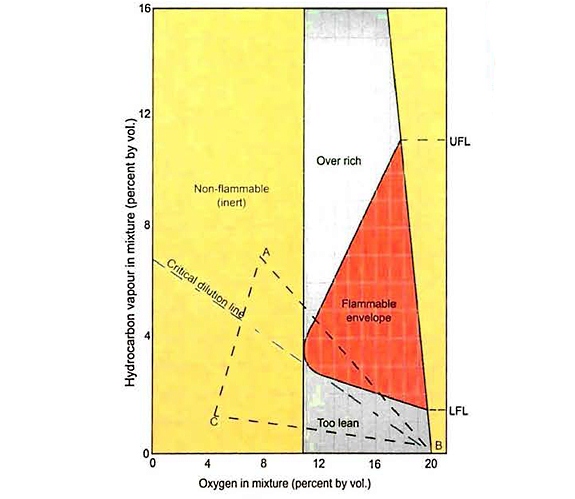
The oxygen content of the mixtures is shown on the horizontal axis, with the hydrocarbon content on the vertical axis (both are measured in percent volume).
The shape of the area labelled as flammable shows clearly how the range is reduced as the oxygen content of the mixture decreases. It is also clear, if the oxygen content is lower than the level at the left extremity of the flammable envelope, that the mixture is not flammable.
For most hydrocarbons this limiting oxygen concentration is about 12 % (vol). However, a figure of 5 % oxygen (vol) is usually adopted on gas carriers to ensure a non-flammable atmosphere, which allows for any lack of mixing or gas pockets within the tank. Lower oxygen levels will certainly be specified if the cargo is oxygen-reactive and may be required for some flammable cargoes by local regulations or the shipper’s requirements.
For further information on inerting and gas-freeing procedures, with reference to figure 21, see point “The use of inert gas” below.
Inert Gas and Nitrogen
“Inert gas” is a gas that is used to prevent the combustion of flammable vapours. The most common types of inert gas used are nitrogen (supplied from shore or produced on board by air separation) or the gas mixture produced by combustion (which comprises mainly nitrogen and carbon dioxide (CO2) plus some residual oxygen).
The term “inerting” means the replacement of air in the system to create an oxygen deficient atmosphere and may involve using either inert gas or nitrogen, according to the shippers’ requirements. Throughout this publication the term inert gas is used for a gas produced by combustion. The use of the word nitrogen can mean pure nitrogen obtained from shore or nitrogen gas without CO2 but with some oxygen present (as produced by shipboard separation systems).
Read also: Overview of the Carriage of Liquefied Gases by Sea
The IGC Code gives only limited requirements in respect of inert gas or nitrogen production plant. The Code recognises that inerting is possible with gas taken from shore, so it is not an IMO requirement to install nitrogen or inert gas producing plant on board gas ships. While shore supply is available from many major terminals it may not be obtainable in more remote ports. For this reason, many gas carriers are fitted with equipment to produce inert gas or nitrogen that provide additional operational flexibility. In practice, the specification for any inerting plant fitted on board largely depends on the trade for which the ship is intended.
Propulsion exhaust (flue gas) is not used to produce inert gas on board gas carriers due to the lack of cleanliness of the propulsion exhaust gas. Instead, it is produced by burning distillate oil in a special inert gas generator (IGG). In some installations, boil-off gas (BOG) is burned in a combination IGG/g as combustion unit (GCU) to produce inert gas. Nitrogen may also be produced on board by separation of air using either a membrane air separation unit or a pressure swing adsorption (PSA) generator. A small percentage of oxygen usually remains in the nitrogen produced on board, although higher purity can be obtained if the production rate is reduced.
Typical compositions for inert gas and nitrogen produced on board are shown in table 8.
| Table 8. Typical compositions of inert gas produced on board gas carriers | ||
|---|---|---|
| Component | Inert gas by combustion | Nitrogen from air separation |
| Nitrogen | 85 to 89 % | Up to 99,5 %** |
| Carbon dioxide | <14 % | <30 ppm |
| Carbon monoxide | 100 ppm (max) | – |
| Oxygen | 0,5 %* | 3 %** |
| Sulphur oxides | 10 ppm (max) | – |
| Oxides of nitrogen | Traces | – |
| Dew point | minus 45 °C (-45 °C)*** | minus 70 °C (-70 °C) at atmospheric pressure |
| Ash and soot | ‘0’ on Bacharach scale | – |
| Relative density (air = 1,00) | 1,035 | 0,9672 |
| *Depends on combustion conditions **Depends on nitrogen production rate ***Depends on dryer equipment | ||
The Use of Inert Gas
On board gas carriers, inert gas may be used to prevent the formation of a flammable mixture in cargo tanks during cargo grade change, preparation to load the first cargo after drydock or when gas-freeing prior to drydock, inspection or repairs. Inert gas may also be used in the hold or
interbarrier spaces.
To help ensure the safety of this operation, regular measurements should be taken to evaluate the atmosphere throughout the tank at the various stages, using properly calibrated instruments. During the process, it is important to use reasonable margins of safety to allow for any non-homogeneity in the tank atmosphere and any lack of precision in the flammable envelope. The range of flammable limits applicable to the gases involved should be considered (see table 6). The flammable envelope data, as given in Reference 2.1, can also be used for guidance.
Before loading, the atmosphere requirements for the cargo tank will always be subject to the shippers’ requirements. For example, nitrogen will generally be required for inerting operations before loading a cargo that is sensitive to oxygen or CO2.
For flammable hydrocarbon cargoes, such as LPG or LNG, the generally accepted standard is for the tank oxygen content to be at or below 5 % (vol). Prior to aeration, a hydrocarbon content at or below 2 % (vol) will usually have been achieved during the inerting process. Different standards may be required in particular trades, which is why the shipper’s advice should usually be sought.
In addition to the oxygen content, dryness is another essential consideration in respect of inert gas quality. Any moisture contained within the inert gas can condense if cold temperatures are encountered. Therefore, combustion type inert gas in particular is dried carefully before use to prevent ice or hydrate formation in the cargo system. Wet inert gas could also cause significant condensation and corrosion in tanks or hold spaces.
The IGC Code requires that gas carriers constructed with a complete secondary barrier must maintain the hold or barrier space in an inert condition when carrying flammable cargoes.
This is to keep the atmosphere in these barrier spaces non-flammable, dry and at a pressure slightly above atmospheric. The inert gas creation capacity required for this is much lower than that required for inerting cargo tanks and some ships are fitted with liquid nitrogen storage tanks for this purpose, although most now use a small membrane type nitrogen generator with sufficient capacity to cope with the extra demand when cargo tanks are cooled down. Ships with partial secondary barriers have to be able to inert the barrier spaces immediately if there is leakage when carrying a flammable cargo.
The Chemical Compatibility of Cargoes with Inert Gas or Nitrogen
Combustion generated inert gas cannot be regarded as chemically inert as the CO2 in the mixture can react with certain cargoes, such as ammonia.
Inert gas can also contaminate some cargoes. For example, if CO2 is in contact with propylene, some will dissolve in the liquid and will interfere with subsequent polymerisation reactions in industrial processes, such as those required for the manufacture of polypropylene plastic. For this reason nitrogen may typically be specified for change of grades that need a gas that is both chemically inert and a fire suppressant. Only high purity nitrogen is fully chemically compatible with the entire range of liquefied gas cargoes.
Carbon
Particles, in the form of ash and soot, can be caused by poor combustion and may contaminate many cargoes.
Carbon monoxide
This can be generated, by poor combustion, in concentrations sufficient to cause serious difficulties and safety issues during any subsequent aeration operations. Carbon monoxide has a OEL-TWA of 25 ppm (ILO International Chemical Safety Card (ICSC)) and is both colourless and odourless. Toxic levels of carbon monoxide may still be present in cargo tanks after aeration is believed to be complete and several fatalities have been caused in this way. Note that poor combustion in the IGG will typically produce carbon (ie soot) at the same time.
Carbon dioxide
This will freeze at temperatures below about minus 55 °C (-55 °C). It will contaminate the cargo if carriage temperatures are particularly low, which may occur with LNG, so special operational procedures are needed to avoid this problem. Carbon dioxide will also contaminate ammonia cargoes by reacting to produce carbamates. Both solid carbon dioxide and carbamate formation result in cargo contamination and operational difficulties such as clogging of pumps, filters and valves.
Moisture
If this is in inert gas it can condense and form hydrates with hydrocarbon cargoes and cause surface corrosion on cargo tank steel. If a cold cargo is to be loaded it is, therefore, important that the inert gas in the cargo tanks has a sufficiently low dew point to avoid any water vapour freezing out and causing other operational difficulties. Condensation in hold spaces can also cause excessive swelling of the wooden blocks, where fitted, that are used to support the cargo tanks.
Oxygen
This is incompatible with butadiene, isoprene, VCM, ethylene oxide and propylene oxide, even in the low percentages found in shipboard produced inert gas. If they are in contact with oxygen, these cargoes may combine with it to form peroxides and polymers.
The Physical Properties of Liquefied Gases and their States of Matter
Most substances can exist in one of three “phases”:
- solid,
- liquid,
- or gas.
The most commonly experienced example of this is water (H2O). When cold, in the solid phase we call ice, the water molecules are held together in a matrix by strong inter-molecular forces. When heated, the ice melts and becomes the liquid phase we call water, where the forces between the molecules are much weaker. When heated further, the higher energy of the water molecules is sufficient to overcome these attraction forces and the molecules fly off the surface to become steam when the water boils.
Temperature, Heat Energy and Phase Change
Heat is the form of energy that, when added to a substance, increases the speed of movement of the molecules. It is this increased molecular movement that eventually causes the material to change phase from solid to liquid and to vapour. The temperature (“T“) of the material gives some measure of the energy in the material, but it is important to understand that temperature shows only part of the picture.
It is also important to note that heat is given out when a gas condenses to form liquid or when a liquid is cooled to change it into the solid phase. The phase change process is reversible.
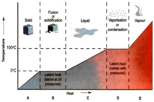
If we take a cold block of ice and add heat to it under normal room conditions, we can measure the rise in temperature using a thermometer. The heat added can be “sensed” in this way, so it is defined as “sensible heat”. However, when the ice reaches 0 °C, the temperature stops rising even if the rate of heat input remains constant. This is because the heat energy is being used to break up the bonds between the ice molecules to form water. The heat input required to melt the ice cannot be sensed by a thermometer so it is called the “latent” (or “hidden“) heat. As the solid ice is melting, this energy is known as the “latent heat of fusion”. The temperature at which this phase change occurs is known as the melting point of water and is defined as 0 °C.
If the water is heated further under ambient conditions, the movement of the water molecules increases steadily. The water temperature rises, so this heat added is again “sensible“. Some of the molecules at the liquid surface go into the atmosphere and the pressure exerted by this process is called the vapour pressure of the liquid at that temperature. When the water reaches 100 °C, sufficient molecules fly off the surface to give a pressure equal to the pressure of the atmosphere above the liquid and the water is said to be at its boiling point. The heat required to overcome the interaction between the liquid molecules and move them into the vapour phase is known as the “latent heat of vaporisation“.
The molecules at the boiling water surface are at the same temperature and pressure (ie both phases are in equilibrium). When the water molecules (ie steam) are in equilibrium with the liquid phase, the vapour is said to be “saturated“. If the steam is heated further, it is said to be “superheated“.
The freezing and boiling points of pure water at standard atmospheric pressure are defined as 0 °C and 100 °C. The melting point of most solids is independent of pressure, so it usually occurs at a specific temperature. However, the process of vaporising a liquid is highly dependent on the pressure acting on the liquid. For example, if water is evaporated under vacuum conditions, the process occurs at a temperature below 100 °C. If the container is pressurised, water turns into steam at temperatures above 100 °C. It is, therefore, proper to use the term “saturation temperature” for the point at which the vapour pressure (P) equals that of the surroundings. By convention, the term “boiling point” is used to describe evaporation at atmospheric pressure.
It is important to note that the saturation temperature is not the only parameter affected by the evaporating pressure conditions. The value for the latent heat of vaporisation also varies significantly, depending on evaporation pressure.
Specific Heat Enthalpy and Antropy
The amount of heat required to raise the temperature of a unit mass of material by 1° is known as the “specific heat” of that material. The most common units used are metric, so the figure may be stated in
.
The specific heat of superheated vapour depends on whether that vapour is heated under conditions of constant volume or constant pressure.
Temperature alone cannot completely define the amount of heat energy contained in a quantity of liquefied gas. Where a significant amount of energy is contained in the vapour phase due to its volume and pressure, a quantity called “enthalpy” is used to define the amount of heat within the system. Enthalpy is the total sum of the internal energy of the material (indicated by its temperature and specific heat) plus the pressure energy contained in the volume of vapour in the system. Enthalpy is a useful measure of energy changes during a process cycle such as reliquefaction. The symbol “H” is commonly used for enthalpy.
If heat is added to a material, or removed from it during a reversible process, the quantity of heat transferred, divided by the temperature of the material is called its entropy. Entropy is the dispersion of energy among the molecules of that material.
During a reversible process such as reliquefaction, entropy changes occur at various stages of the cycle, but overall there is no net change of entropy in the system. The symbol “S” is commonly used for entropy.
Phase Change – a Summary
If we look at the behaviour of ice, water and steam, we can understand this as follows:
A+B When cold ice (less than 0 °C) is heated, its temperature (T) and enthalpy (H) increase until it melts. The temperature of the ice block will increase until it reaches 0 °C, when melting begins. The specific heat is the amount of heat required to raise the temperature of 1 kg of ice by 1 °C. The temperature of the ice will stay at 0 °C until the latent heat of fusion has been absorbed. For ice, the latent heat is 80 kcal/kg or 335 kJ/kg.
C As the heating continues, the water will warm up and the vapour pressure (P) will increase until, at the saturation temperature, it equals the pressure on the liquid surface. For pure water at standard atmospheric pressure, this is 100 °C. The amount of heat required to raise the temperature of 1 kg of water from 0 °C to 100 °C is 100 kcal or 420 kJ.
D The liquid then absorbs the latent heat of vaporisation (which is 540 kcal/kg or 2,260 kJ/kg) as it evaporates to form steam. During evaporation, the fastest moving molecules escape from the surface of the water. When the entire liquid body changes phase it is said to be boiling, and this happens when the saturated vapour pressure (SVP) of the water is equal to the external pressure on it and saturation temperature is reached.
E The vapour is saturated if it is in equilibrium with the liquid, but becomes superheated when heated further after all the liquid hm evaporated. The value of the specific heat of steam depends on whether it is heated at constant volume or constant pressure.
Saturated Vapour Pressure (SVP)
To further understand the behaviour of History and Future Predictions of the Liquefied Natural Gas Shippingliquefied gas cargoes it is important to have a clear understanding about the SVP of the cargo liquid. For clarity, it is assumed the cargo is chemically pure (the behaviour of cargo mixtures will be discussed in point “Liquefied gas mixtures, their vapour pressures and compositions” below).
The vapour space above a liquefied gas cargo is in a state of continuous motion. Molecules at the liquid surface are constantly leaving to enter the vapour phase, and molecules are always returning from this space into the liquid phase.
If the vapour space can accept more molecules from the liquid at its current temperature it is said to be “unsaturated“. Conversely, a “saturated” vapour phase is one that is in equilibrium with the liquid phase at the prevailing temperature. In the saturated condition, the vapour space cannot accept any more molecules from the liquid without a corresponding exchange of molecules from the vapour to the liquid. (Note: it is important to understand that the terms “saturated” and “unsaturated” here are used to describe the vapour phase composition and not the chemical bonds w ithin the molecules as outlined in point “Saturated and unsaturated hydrocarbons” above).
At a specific temperature, the force exerted by a saturated vapour is called the SVP of the liquid at that temperature. Different methods can be used to measure the SVPs of liquids and the most common one is illustrated in figure 23.
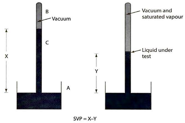
The measuring apparatus is based on a mercury barometer and consists of a mercury reservoir (A) into which is placed an inverted barometric tube (C) that has been filled with mercury. The space above the mercury in the tube is a vacuum (B) and the height of mercury column (X) is a direct measure of the absolute pressure of the atmosphere.
A small amount of the test liquid is put into the barometric tube and rises to the vacuum space where it partially vaporises and exerts its SVP. This vapour pressure in turn pushes down the mercury in the tube to a new level (Y). The SVP of the test liquid is, therefore, indicated by the height difference in the mercury column (ie X-Y). This is measured directly as mm of mercury, which can then be converted into other units.
If the mercury is heated the test liquid will also warm up and its SVP will increase. This will press down the mercury level even further. In this way the SVP of the liquid can be determined over a range of temperatures.
Different liquefied gases exert different vapour pressures, as can be seen in figure 24, which shows the SVP for each of the common cargoes over a range of temperatures. For clarity, pressures are shown on a logarithmic scale in units of kg/cm2 and are plotted on an “absolute” pressure scale (ie a scale where zero pressure equals a perfect vacuum).
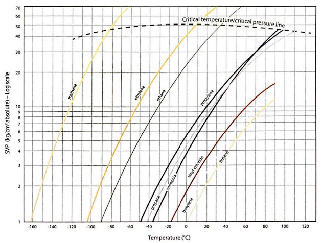
Comparing the pressure curves, it can be seen that at a given temperature, lighter molecules exert a greater vapour pressure than heavier molecules.
The horizontal axis indicates atmospheric pressure (ie 1 kg/cm2(o)), so the point where the curves cross this line shows the temperature at which these cargoes would be transported in fully-refrigerated or fully insulated containment systems. In other words, the temperature at which the SVP of the cargo is equal to atmospheric pressure.
The correct pressure unit is the pascal (Pa), which can indicate a gauge reading or an absolute pressure. Other units, such as “bar”, kg/cm2 (kilograms force per square centimetre), atmospheres or mm Hg (millimetres of mercury Hg), may also be encountered. Conversion factors for these various pressure units are given in table 9.
| Table 9. Conversion factors for units of pressure | |||||||||||
|---|---|---|---|---|---|---|---|---|---|---|---|
| kPa | bar | Sid atm | kg.f/cm2 | lb.f/inch2 (psi) | lb.f/ft2 (psf) | mm (Merkury) | inches (Merkury) | inches (Water) | feet (Water) | metres (Water) | |
| kPa | 1 | 0,01 | 0,0099 | 0,0102 | 0,1450 | 20,88 | 7,50 | 0.2953 | 4,015 | 0,3346 | 0,1020 |
| bar | 100 | 1 | 0,9869 | 1,020 | 14,50 | 2,089 | 750,1 | 29,53 | 402,2 | 33,52 | 10,22 |
| Sid atm | 101,325 | 1,013 | 1 | 1,033 | 14,70 | 2,116 | 760 | 29,92 | 407,5 | 33,96 | 10,35 |
| kg.f/cm | 98,039 | 0,9807 | 0,9678 | 1 | 14,22 | 2,048 | 735.6 | 28,96 | 394,4 | 32,87 | 10,02 |
| lb.f/inch2 (psi) | 6,8966 | 0,06895 | 0,06805 | 0,07031 | 1 | 144 | 51,72 | 2,036 | 27,73 | 2,311 | 0,744 |
| lb.f/ft2 | 0,0479 | 4,788×104 | 4,725×104 | 4,882×104 | 0,006944 | 1 | 0,3591 | 0,01414 | 0,1926 | 0,01605 | 0,004891 |
| mm Hg | 0,1333 | 0,001330 | 0,001316 | 0,0011360 | 0,01934 | 2,785 | 1 | 0,03937 | 0,5362 | 0,04499 | 0,01362 |
| inches Hg | 3,3864 | 0,03386 | 0,03342 | 0,03453 | 0,4912 | 70,73 | 25,4 | 1 | 13,62 | 1,135 | 0,3459 |
| inches H2O | 0,2491 | 0,001486 | 0,002454 | 0,002535 | 0,03606 | 5,193 | 1,865 | 0,07342 | 1 | 0,0833 | 0,02540 |
| ft H2O | 2,9886 | 0,02984 | 0,02944 | 0,03042 | 0,4327 | 62,31 | 22,38 | 0,8810 | 12 | 1 | 0,3048 |
| metres H2O | 9,8039 | 0,09789 | 0,09660 | 0,0998 | 1,420 | 204,4 | 73,42 | 2,891 | 39,37 | 3,281 | 1 |
Note that “bar” is the pressure unit used most frequently in the gas industry. Vapour pressures, although commonly indicated as gauge pressures (ie relative to atmospheric pressure) are, effectively, absolute pressures.
The absolute pressure is obtained by adding the atmospheric pressure to the gauge reading.
For consistency within this publication, “bar” will be used where a gauge pressure is intended and “bara” when absolute readings are intended.
Liquid and Vapour Densities
Liquefied gases have high expansion coefficients compared to normal hydrocarbon liquids, which means that the density of the cargo liquid decreases significantly as the temperature increases. This is shown as Y’ in the graphs for propane in figure 25.
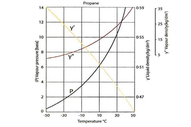
The density of a liquid is defined as its mass per unit volume. This is usually stated in metric tonnes per cubic metre (mt/m3), but it may also be quoted in kilograms per cubic metre (kg/m3), per cubic decimetre (kg/d m3) or per litre (kg/l).
The densities of cargo liquids at their atmospheric pressure conditions (ie fully-refrigerated) are shown in table 10. Fresh water has a density of 1 000 kg/m3, so all the cargoes listed in table 10, with the exception of chlorine, have lower densities. This means that, in the event of a spillage onto water, the liquids would tend to float before evaporating, except for ammonia which would dissolve.
| Table 10. Physical properties of gases | |||||||
|---|---|---|---|---|---|---|---|
| Gas | Atmospheric boiling point (°C) | Critical Temperature (°C) | Critical pressure (bara) | Condensing ratio dm3 liquid 1 m3 gas | Evaporating ratio m3 vapour m3 liquid | Liquid relative density at atm. boiling pt. (water = 1) | Vapour relative density (air = 1) |
| Methane | minus 162 (-162) | minus 82,5 (-82,5) | 44,7 | 1,631 | 613 | 0,427 | 0,554 |
| Ethane | minus 88,6 (-88,6) | 32,1 | 48,9 | 2,453 | 408 | 0,540 | 10,48 |
| Propane | minus 42,3 (-42,3) | 96,8 | 42,6 | 3,380 | 296 | 0,583 | 1,55 |
| n-Butane | minus 0,5 (-0,5) | 153 | 38,1 | 4,32 | 231 | 0,600 | 2,09 |
| i-Butane | minus 11,7 (-11,7) | 133,7 | 38,2 | 4,36 | 229 | 0,596 | 2,07 |
| Ethylene | minus 103,9 (-103,9) | 9,9 | 50,5 | 2,20 | 455 | 0,570 | 0,975 |
| Propylene | Propylene minus 47,7 (-47,7) | 92,1 | 45,6 | 3,08 | 325 | 0,613 | 1,48 |
| α-Butylene | minus 6,1 (-6,1) | 146,4 | 38,9 | 4,01 | 249 | 0,624 | 1,94 |
| γ-Butylene | minus 6,9 (-6,9) | 144,7 | 38,7 | 4,00 | 250 | 0,627 | 1,94 |
| Butadiene | minus 5,0 (-5.0) | 161,8 | 43,2 | 3,81 | 262 | 0,653 | 1,88 |
| Isoprene | 34 | 211,0 | 38,5 | 0,67 | 2,3 | ||
| Vinyl chloride | Vinyl chloride minus 13,8 (-13,8) | 158,4 | 52,9 | 2,87 | 348 | 0,965 | 2,15 |
| Ethylene oxide | 10,7 | 195,7 | 74,4 | 2,13 | 469 | 0,896 | 1,52 |
| Propylene oxide | 34,2 | 209,1 | 47,7 | 0,830 | 2,00 | ||
| Ammonia | minus 33,4 (-33,4) | 132,4 | 113,0 | 1,12 | 893 | 0,683 | 0,597 |
| Chlorine | minus 34 (-34) | 144 | 77,1 | 2,03 | 493 | 1,56 | 2,49 |
The density/temperature relationship of the saturated propane vapour is shown on the curve Y” in figure 25. The saturated vapour density increases significantly as the cargo liquid temperature rises. This is because more molecules transfer from the liquid to the vapour phase to increase the pressure and this increases the mass per unit volume in the vapour space.
Cargo vapour density is usually stated in units of kilograms per cubic metre (kg/m3).
Table 10 also shows that the vapours of most liquefied gas cargoes are heavier than air under standard conditions of temperature and pressure. If a heavier than air vapour is released to atmosphere it will tend to settle to the lowest levels and may not disperse readily if there is no air movement. Methane, ammonia and ethylene are normally lighter than air.
Liquid to Vapour Volume Ratios
During Terminal Operations for LNG or LPG Carrier after Arriving in Portcargo handling operations involving a phase change (eg when condensing boil-off vapour or when evaporating liquid in a vaporiser), it is important to have an idea about the volume changes involved. This can be important for cargo calculations, such as “gassing-up” quantity estimates or for sizing the equipment handling vapour or its liquid condensate.
Table 10 includes data on both the condensing ratio and the evaporating ratio. The condensing ratio is the quantity of liquid formed (in m3 or litres) at atmospheric saturation temperature from 1 m3 of superheated vapour at normal temperature and pressure (NTP) (ie 1 bara and 20 °C). The evaporating ratio is calculated for the same conditions.
Spillage of Cargo Liquid
When a gas is stored as a liquid, whether under pressure or refrigerated, it will vaporise on being released to the atmosphere, taking heat from the surroundings. Depending on the liquid spilled, the spill size and whether the spill is on land or water, the rate of vaporisation and the temperature and density of the ensuing vapour cloud will vary. Almost certainly the cloud will be low-lying (only methane, when warmer than minus 100 °C (-100 °C), ethylene and ammonia are lighter than air – see table 10). Initially, the cloud will be cold and will drift downwind. It will generally be visible as a white cloud of condensed atmospheric water vapour. The characteristics of this cloud, in terms of its flammability and oxygen content, are discussed in point “Flammability/flammable range” above. A further description of the hazards associated with spillage of a liquid cargo can be found in article “Basics of safety on gas carriersVaporisation of spilled liquid“.
Viscosity of liquid cargoes
Viscosity is the property of a fluid that, due to the friction between the molecules, restricts one layer of the liquid from moving over an adjacent layer. Viscosity is important in determining the lubricating properties of liquid.
The majority of liquefied gases have poor lubricating properties when compared to lubricating oils or even water, as shown in table 11.
| Table 11. Viscosity comparison of liquid cargoes | |||||
|---|---|---|---|---|---|
| Liquid (@ Temperature) | Representative Lube Oil @ 70 °C | Water @ 100 °C | Ammonia @ -33 °C | Propane @ -45 °C | LNG@ -160 °C |
| Viscosity (contipoiso) | 28,2 | 0,282 | 0,250 | 0,216 | 0,115 |
| Specific hoot (kcal/kg/°C) | 0,70 | 1,00 | 1,07 | 0,50 | 0,80 |
| Latent hoot of vaporisation (kcal/kg) | 35,0 | 539,00 | 326,58 | 101,00 | 123,00 |