This article describes only what may be considered to be the essential aspects of cargo transfer and storage equipment that are needed for Liquefied natural gas terminals.
- Safe Jetty Designs
- Cargo Transfer Systems
- Hoses
- Marine loading arms (MLAs)
- Vapour return
- Insulating flanges
- Shore Storage
- Pressurised storage at ambient temperature
- Storage in semi-pressurised spheres
- Refrigerated storage at atmospheric pressure
- Construction materials and design
- Ancillary Equipment
- Pressure relief venting
- Pipelines and valves – engineering standards and surge pressure
- Pumps, compressors and heat exchangers
- Instrumentation
- Product metering
- Pressure, temperature and level instrumentation
Other equipment relevant to terminal operations for liquefying gas for loading or for vaporising the liquefied gas for delivery to the markets are described in relevant industry standards and, while referred to, will not be described in great detail here.
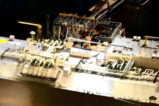
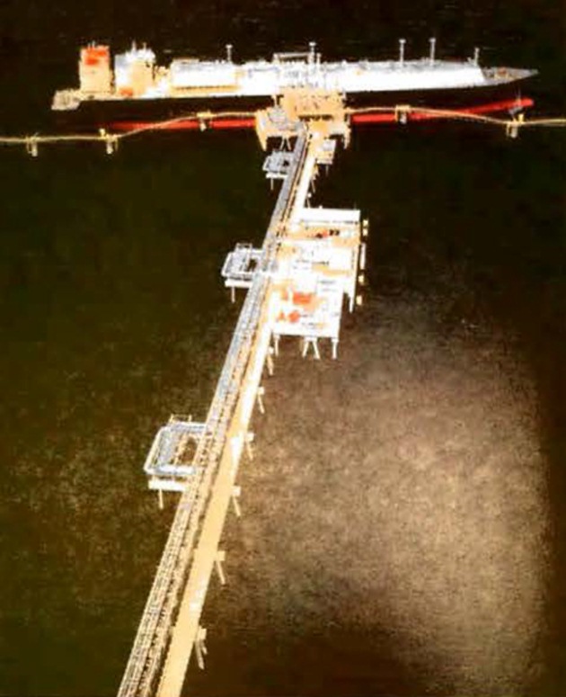
Safe Jetty Designs
The ship/shore interface is a safety critical area. Safety focused jetty design, and the equipment it needs, requires a good understanding of ship operating parameters. Terminal designers will consider:
- The berth’s position (ie location and orientation) with regard to other marine traffic;
- the berth’s position (ie location) and proximity to other users;
- elimination of nearby ignition sources;
- distances between adjacent berths;
- the range of acceptable ship sizes that may visit the terminal;
- the availability of tugs with sufficient power to assist with berthing and unberthing;
- visiting ships’ parallel body length, for breasting dolphin positioning;
- suitability of the jetty fenders;
- positioning of shore mooring points of suitable strength;
- tension monitoring equipment for mooring line loads;
- water depths at the jetty and its approaches;
- indicators for a ship’s speed of approach to the jetty;
- the use of marine loading arms (MLAs) and their safe operating envelopes;
- emergency shutdown (ESD) systems, including interlinked ship/shore control;
- suitable plugs and sockets for the ship/shore link;
- an emergency release coupling (ERC) on the MLAs;
- vapour return facilities;
- nitrogen supply to the jetty;
- gas detection systems;
- the positioning of ship/shore gangways;
- designs to limit surge pressures in cargo pipelines;
- verbal communication systems;
- the development of jetty information and regulations;
- life-saving and fire-fighting equipment;
- systems for warning of the onset of bad weather;
- maintainability;
- the development of emergency procedures.
While port approach issues, such as the suitability of the vessel traffic management systems, sizing of fairways and turning basins, may also need to be considered, they are outside of the scope of this publication.
(See “Aspects Affecting the Berthing Operations of Tankers to Oil and Gas Terminals” (Reference 2.23).
Cargo Transfer Systems
Cargo transfer systems vary widely between the different liquefied gas trades. In the liquefied natural gas (LNG) trade there are only about 100 terminals in operation and LNG cargo transfer has mainly involved handling bulk transfer of LNG between an LNG carrier and an onshore terminal. Condensate or natural gas liquid (NGL) cargoes may also be handled in some LNG liquefaction terminals.
However, there are many hundreds of terminals for liquefied petroleum gases (LPGs) and chemical gases. Loading terminals range from oil refineries to chemical or fertilizer plants and there is a wide variety of discharge ports.
Cargo transfer at the ship/shore interface may be by MLAs, often referred to as hard arms, or by hoses. The LNG industry has traditionally used MLAs, although hose systems are often used for ship to ship (STS) transfer. MLAs are the most commonly preferred system for LPG transfer and these are in use at the majority of the medium and large terminals, although the use of hoses is common at many small terminals, particularly those handling pressurised LPG.
- NFPA 59A “Standard for the Production, Storage, and Handling of Liquefied Natural Gas (LNG)” (Reference 2.24);
- BS EN 1473 “Installation and equipment for liquefied natural gas – Design of onshore LNG installations” (Reference 2.25);
- BS EN 1474 Part 1 “Installation and equipment for liquefied natural gas – Design and testing of marine transfer systems” (Reference 2.26) (superseded in 2016 by ISO 16904);
- ISO 16904 “Petroleum and natural gas industries – Design and testing of LNG marine transfer arms for conventional onshore terminals” (Reference 2.27);
- BS EN 1474 Part 2 “Design and testing of transfer hoses” (Reference 2.26);
- ISO 28460 “Petroleum and natural gas industries – Installation and equipment for liquefied natural gas – Ship-to-shore interface and port operations” (Reference 2.28).
LPG facilities are not so well served, although BS 4089 “Specification for metallic hose assemblies for liquid petroleum gases and liquefied natural gases” (Reference 2.29), API 2510 “Design and Construction of LPG Installations” (Reference 2.30) and NFPA 58 “Liquefied Petroleum Gas Code” (Reference 2.31) are relevant.
Hoses
Hoses will usually be purchased for the purpose intended and specified against a suitable national standard (for example, the hoses used for cargo transfer often comply with British Standard BS 4089 “Specification for metallic hose assemblies for liquid petroleum gases and liquefied natural gases” (Reference 2.29) and composite hoses are often manufactured to British Standard BS 5842 “Specification for thermoplastic hose assemblies for dock, road and tanker use” (Reference 2.32)). At the point of purchase, some of the key specifications to be relayed to the manufacturers will be the minimum and maximum operating temperatures and pressures and the cargoes for which the hose will be used.
During operations the proper handling of hoses is important and hoses of all types will, ordinarily, need to be correctly supported in a hose cradle. This will help to ensure that manufacturers’ recommendations on minimum bending radius (MBR) are met. Care should also be exercised when rigging or moving hoses to ensure that they are not damaged or laid against sharp edges that could weaken the hose.
Hoses should be inspected frequently (before each transfer operation) and tested a t specified intervals (generally not exceeding six months). Where appropriate, pressure testing will be supplemented with measurements for elongation under pressure and with testing for electrical continuity in accordance with manufacturer recommendations. Generally speaking, it is good practice for terminals to provide hoses with quick connect/disconnect couplings (QC/DCs) and ERCs (see point below “Marine loading arms (MLAs)”).
There are three types of cargo hose suitable for liquefied gases; composite, rubber or stainless steel construction.
For LPG, hoses may be of similar construction to those used for LNG, but hoses of synthetic rubber manufacture may also be used.
For LNG, hoses can be of composite construction or of corrugated stainless steel, but the composite type is generally preferred. The majority of LNG cargo transfers, however, are carried out through marine loading arms with the ship alongside a jetty.
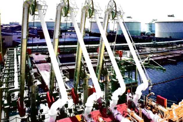
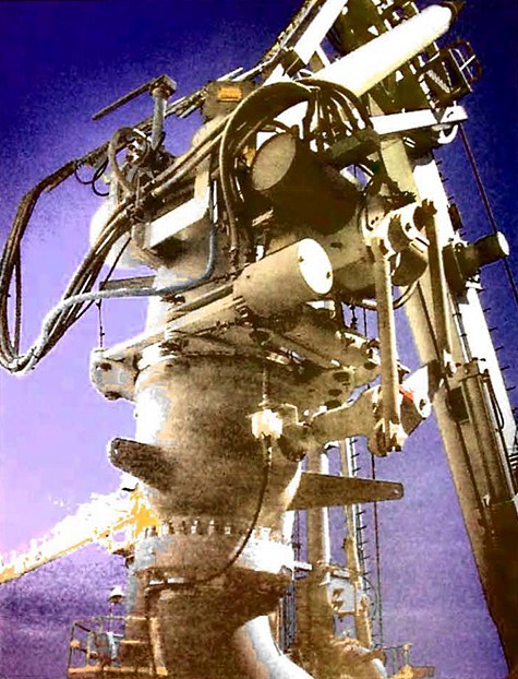
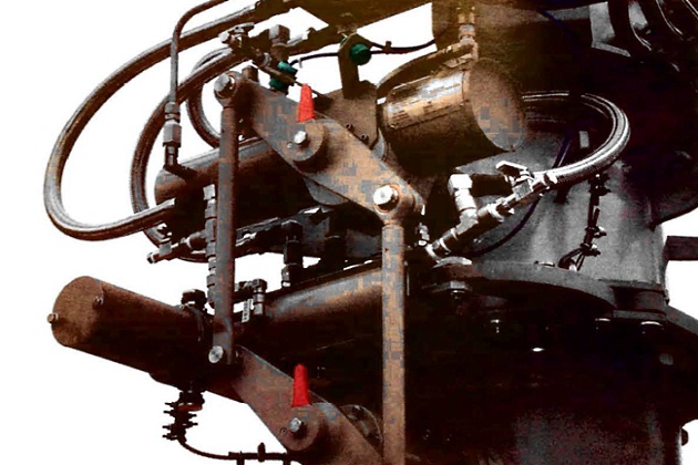
Marine loading arms (MLAs)
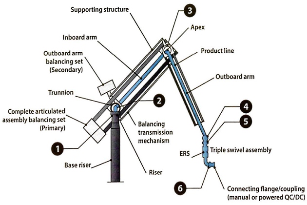
Typical MLAs used for the transfer of liquefied gas are shown in Figures 2 and 4.
The arm is fitted with swivel joints to provide the required movement between the ship and the shore connections.
A counter-balance is provided to reduce the deadweight of the arm on the ship’s manifold connection and to reduce the power required to manoeuvre the arms into position.
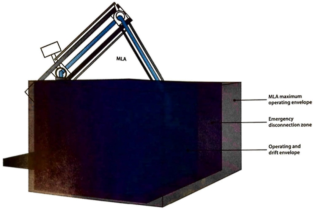
The range, or operating envelope, of the MLA is selected to meet the tidal variation and changes of the ship’s freeboard while loading or discharging. Consideration will also be given to ship surge, yaw, roll, heave and pitch. In addition, an allowance is provided for ship motion resulting from the influences of wind, waves, tidal streams and passing ships. Figure 5 shows a typical operating envelope.
For further information on MLA specifications, refer to OCIMF “Design and Construction Specification for Marine Loading Arms” (Reference 2.33) and ISO 16904 “Petroleum and natural gas industries – Design and testing of LNG marine transfer arms for conventional onshore terminals” (Reference 2.27).
Connecting systems
Connecting systems between MLAs and ships are of two types:
- Basic bolted Flange connections;
- quick connect/disconnect coupling (QC/DC). QC/DCs are used to speed up the connection_and disconnection operation. The coupling is under full manual control, but has hydraulic operation of the clamping/unclamping jaws (see Figure 8). During cargo transfer the QC/DC. ship’s flange connection is maintained by a positive mechanical lock that is usually independent of the hydraulic power supply. Under certain circumstances, where ship movement is a problem, the QC/DC can reduce the risks to safety of personnel.
Failure of a QC/DC coupling, or the ERC, creates the potential for a “guillotine failure” of the transfer line. Therefore, it is essential that these devices are correctly maintained and operated.
Emergency release system (ERS)
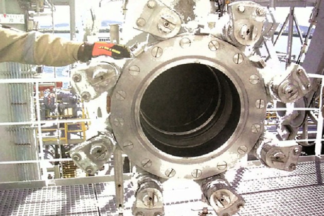
The main manufacturers of this equipment have developed individual clamping and sealing systems for preventing leakage at the presentation flange joint, increasing the risk of differing requirements for the ships’ presentation flange faces. These may be smooth finish, spiral serrated (ie phonographic) finish, Rat face, raised face or a combination of these. Furthermore, some manufacturers have requirements on the maximum internal diameter of the presentation flanges to ensure good contact for positive sealing.
Due to differing terminal requirements, it is suggested that as part of any ship/shore compatibility study the requirements for the ship’s presentation flanges are checked and, if necessary, suitable spool pieces made available on the vessel, or by agreement, supplied by the terminal.
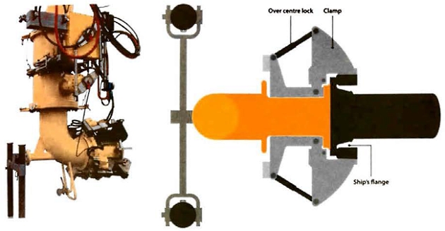
a – Hydraulic QC/DC; b – QC/DC plan view diagram
An ERC is fitted in addition to the normal means of connection and is not used for normal operational connection and disconnection.
The ERS forms a second stage emergency shutdown system in addition to the first stage ESD described in Section 4.1.6. Its purpose is to provide a way to quickly uncouple the MLAs with minimal spillage in an emergency. The system incorporates instrumentation to monitor the ship’s position and also includes alarm and control systems. The physical disconnection is achieved by means of a powered ERC installed in each MLA, as shown in Figure 9.
A typical ERC is shown in Figure 10 and consists of a clamped flange interposed between two ball or butterfly valves. Two hydraulic actuators are mounted on the upper part of the coupler, one for the clamp ring and the other operating both valves via a special linkage. In emergency operation the two valves close first, followed by the release of the clamped coupling. On release, the lower part of the ERC and its attendant valve remain attached to the ship’s manifold while the arm, with the upper part of the ERC and its valve, is free to rise clear of the ship.
Mechanical and hydraulic interlocks prevent the coupling from releasing before the valves are closed. The space between the two valves is kept as small as possible to minimise liquid spillage and they are sometimes referred to as “dry-break” couplings.
It should be noted that usually ESD1 must be initiated before ESD2 so that the loading process is stopped or reduced to a level that will limit surge pressures by the time ESD2 occurs. A typical sequence would be: alarm, followed by ESD1, followed by alarm, followed by ESD2. In defining the ESD1 and ESD2 envelopes for the MLAs, the likely rate of drift of the ship and the time taken to shut down will be accounted for such that shutdown is completed before disconnection (see article “Ship/shore interface for safe loading and unloading of LNG/LPGLinked Emergency Shutdown (ESD) Systems“).
Vapour return
The provision of a vapour return facility between the ship and shore, at both loading and discharging terminals, depends on factors such as applicable environmental regulations, economics, cargo transfer rates, distance of the jetty from the storage tanks, product pressures and cargo temperatures.
At LNG facilities vapour return systems are always fitted and connected to the ship during cargo transfer operations. At a loading facility cargo vapour is returned ashore by the LNGC‘s compressor(s). The return vapour may be sent to a flare or boil-off gas (BOG) station (where installed) for recycling as either feed or fuel gas. A flare system provides essential back-up.
At a discharge port vapour is returned to the LNGC. In both load and discharge ports, vapour recovery systems are necessary for tank pressure control on both sides, ie ship and shore.
A BOG compressor station fulfills three purposes:
- Handling of storage tank boil-off vapour.
- Management of returned vapour from the LNGC.
- Minimises the need for operational flaring and reduces environmental impact.
LPG terminals
While having a terminal vapour return system in place is generally considered to be best practice, many existing LPG and chemical gas terminals either do not have such facilities or do not regularly use them. If vapour return systems are fitted, it is not uncommon to find them connected and only utilised if cargo tank pressures become difficult to manage and cannot be controlled by the loading rate or capacity of the ship’s reliquefaction plant. In such cases the vapour return line is usually directed to the shore flare system to prevent possible contamination by previous cargoes.
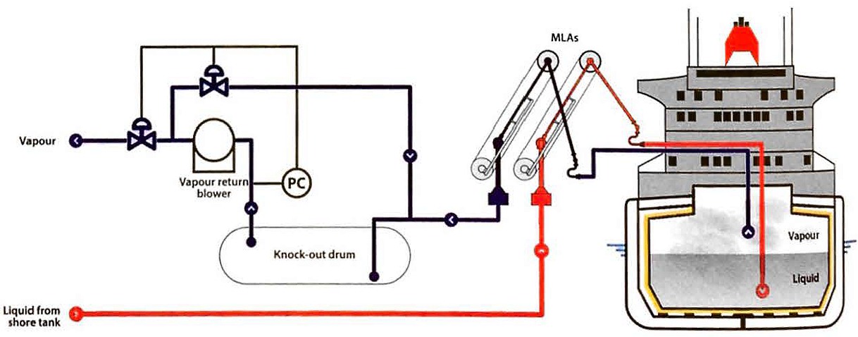
Where the terminal’s vapour return line is exceptionally long, or of relatively limited diameter, the vapour returned ashore from the gas carrier may require the use of a terminal vapour blower or compressor to boost the pressure of the return gas from the ship to the terminal’s return gas handling system.
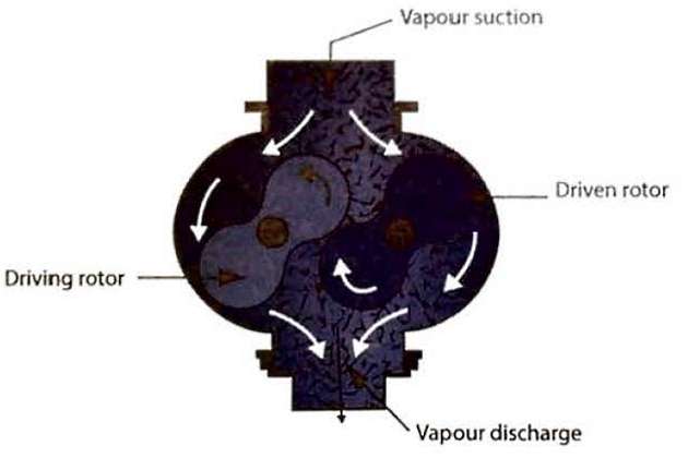
Vapour is transferred from the LP suction to HP discharge as the rotor lobes rotate.
In Figure 13, liquid is prevented from entering the blower by a knock-out drum. To protect against low pressures being created in the ship’s tank, a low suction pressure control that opens a bypass valve between the discharge and the suction sides of the blower is provided.
Receiving terminals may also use vapour return facilities as an integral part of their cargo handling system.
Gassing-up operations using a vapour return is covered in article “Preparation of loading and unloading operations for LNG/LPG carriersGassing-up alongside“.
Insulating flanges
The need to prevent electrical flow through an MLA or hose was discussed in article “Properties of liquefied gasesFlammability/flammable range“. Such currents can be generated by the electrolytic differences between the ship and the shore. It described the practice of inserting an insulating flange in the lower end of the outer arm of the MLA to achieve this aim. Ordinarily, cargo hoses will also be fitted with an insulation flange, although it is also common practice to fit one length of non-conductive hose in each string as an alternative to the flange to perform the same function.
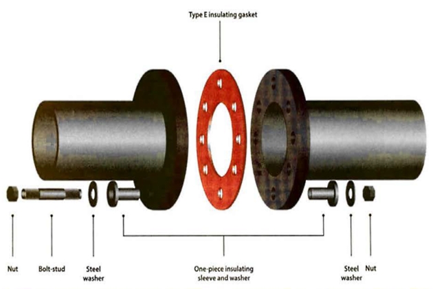
The insulation flange will usually be positioned so that it cannot be shorted out.
The external surfaces of insulating flanges should be kept clean and unpainted and their insulating properties should be regularly tested. (See “A Justification into the Use of Insulation Flanges” (Reference 2.7)).
Shore Storage
In the same way that gas cargoes are transported by sea through control of their pressure and temperature, liquefied gases are stored on shore in either a pressurised, semi-pressurised or refrigerated condition. The most common methods utilised for storing liquefied gases at a terminal are:
1 As a liquid at ambient temperature under pressure in:
- Spherical or cylindrical tanks above ground (Figure 16);
- fully-pressurised storage in a mounded horizontal cylindrical tank (Figure 17);
- underground storage caverns (Figure 18).
2 As a semi-pressurised liquid, at a temperature above the product’s atmospheric boiling point, stored within semi-pressurised spheres (Figure 20).
3 As a fully-refrigerated liquid, at atmospheric pressure and at a low temperature equal to the cargo’s boiling point, in two main categories of storage:
- Above-ground storage:
- single wall tanks (LPG) (Figure 22);
- double wall tanks (LNG, LPG, chemical gases) (Figures 23 and 24);
- double containment tanks (LNG, LPG) (Figure 26);
- full containment tanks (LNG, LPG) (Figure 27);
- Below-ground storage:
- in-ground tanks (LNG) (Figure 29).
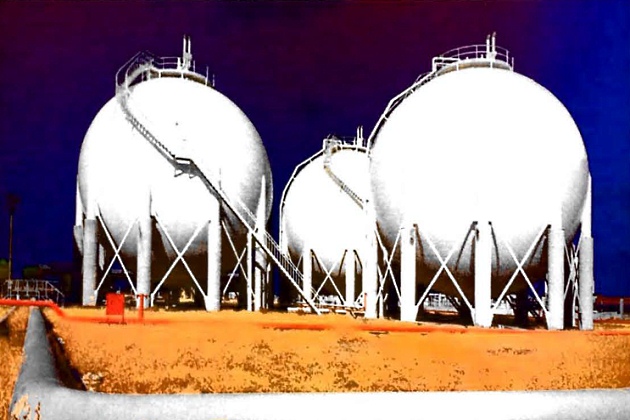
Pressurised storage at ambient temperature
Pressurised storage of liquefied gases is undertaken at refineries, chemical plants, import and export terminals, filling/bulk distribution centres, retail sales outlets and large industrial premises. Individually, the pressure tanks are small when compared to fully-refrigerated gas storage tanks.
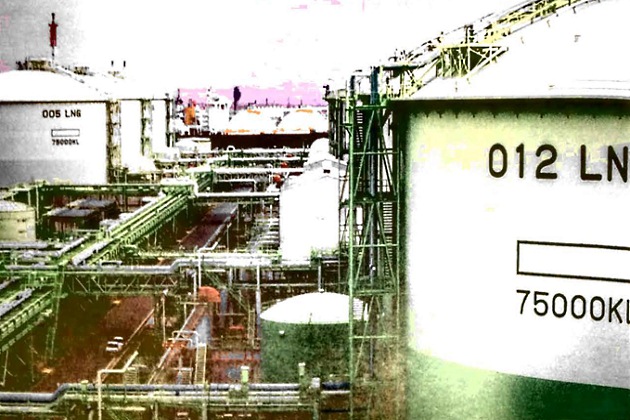
For example, the largest spheres have a capacity of about 5 000 m3, but many distribution terminals have large numbers of cylindrical tanks or spheres to provide total capacities equivalent to the average sized refrigerated terminal. Worldwide, for example, there are several gas storage terminals that have total capacities in excess of 50 000 m3, achieved by the use of 30 or more pressure tanks.
Pressure vessels should be designed, fabricated, inspected and tested in accordance with a recognised pressure vessel code, such as British Standard PD 5500 “Specification for unfired fusion welded pressure vessels” (Reference 2.34) and the American Standard “ASME Boiler and Pressure Vessel Code, Section VIII” (Reference 2.18), and any applicable legislation. The layout of a storage installation will be such that, if product leaked and ignited, the effect on other parts of the complex, or on people or property located outside the terminal, would be minimised.
Read also: Overview of the Carriage of Liquefied Gases by Sea
The storage of quantities of liquefied gases is recognised by regulators as a hazardous industrial activity and has been subject to stricter controls in recent years. For example, the recent amendments to the European Union’s “Seveso” Directive, covering major hazard sites, calls for greater distances than was previously the case, not only between gas storage vessels within the plant, but also between the industrial installation itself and adjacent public facilities.
Storage in above-ground spheres, cylinders or bullets
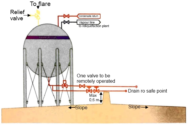
The storage terminal will usually be arranged so that pressure storage vessels, pump bays and loading and discharge facilities are at an appropriate distance from sources of ignition. Fire-fighting access, amongst other things, will also be a consideration in design of facilities. Tanks will, ordinarily, be situated in such a way that spillage from one tank or work area does not flow under any other tank or to any other work area. Each pressure vessel will generally be provided with at least one pressure relief system connected directly to the vapour space, a level gauge, pressure and temperature indicators and a maximum level device such as a high level alarm.
If liquid leaks from a pressurised tank, vapour evolves due to rapid flashing, so maximum ventilation is usually essential to ensure dispersion. This is facilitated by laying out the ground under a tank in such a way that any leak would drain to a catchment area where spill vaporisation can be more closely controlled. Spill vaporisation areas often contain gravel to maximise surface area and encourage evaporation. Retaining walls around a catchment area will not generally be more than 0,6 metres high and will not totally surround the area so that air can circulate freely.
Each gas storage vessel and each bulk loading or discharge facility should be provided with a fire protection system that will ensure the tank’s structural integrity under fire conditions. Fire protection may be achieved by the use of spacing, location, insulation or similar systems and by the use of cooling water. All above-ground pressure storage will generally have fixed spray systems to ensure that all tank surfaces and product pipelines in the immediate vicinity, that would be exposed to thermal radiation in a fire, are protected by a film of cooling water.
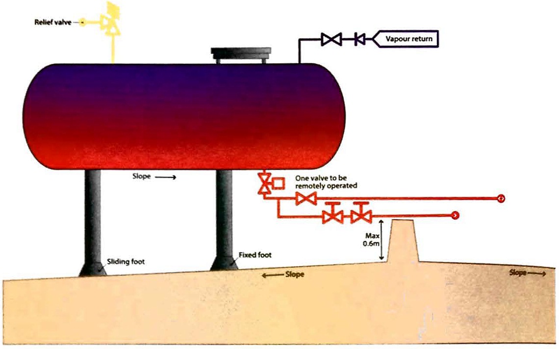
Storage in mounded horizontal cylinders
Concerns about the safety of areas surrounding gas storage depots in the event of a major containment failure has meant that some countries may require the use of mounded tanks under
certain circumstances.
The first mounded gas storage tanks were installed in Germany in 1959 and units can be found across the world. The largest mounded cylinders are 4 000 m3 in size, but several countries utilise small mounded, semi-underground and fully buried tanks, in the size range 10 to 100 m3. These are to support marketing operations, such as automotive LPG retailing, and networked LPG supply systems.
The earth that covers mounded tanks protects them from fire engulfment and radiation from close proximity fires, so extensive water deluge systems are generally unnecessary and the BLEVE form of catastrophic tank failure is unlikely (see article “Basics of safety on gas carriersBLEVE“). In addition, the amount of space required between mounded tanks is much less than that specified for above-ground tanks, so less land area is required for a given storage capacity.
Another advantage of mounded tanks relates to the sun impingement factor. Because direct sunlight does not fall upon such units, the design pressure of a tank for the storage of LPG can generally be set at about 12 bar rather than the 16 to 18 bar required for an above-ground tank. The shell thickness of the mounded vessel does not usually have to be so great and the use of internal ring stiffeners along the length of the tank helps to avoid the need for thick shells.
Most mounded tanks are placed on beds of sand, a type of foundation that provides uniform support over the length of the vessel. The number of connections and nozzles fitted to mounded tanks is kept to a minimum. Furthermore, if a submerged pump is fitted, all connections should be made through a top outlet only.
A concern raised about earth covered pressure tanks is the difficulty in providing adequate protection against corrosion, although the service records of these units have shown that this is not actually a problem. After the finished tank is shot blasted it is primed prior to being wrapped with a heavy anti-corrosion coating, such as polyester glass-flake coatings. A compatible cathodic protection system, usually of the impressed current type, completes the corrosion protection package.
Underground storage
Pressurised LPG may also be stored in underground caverns that are either leached from salt deposits or mined from rock formations.
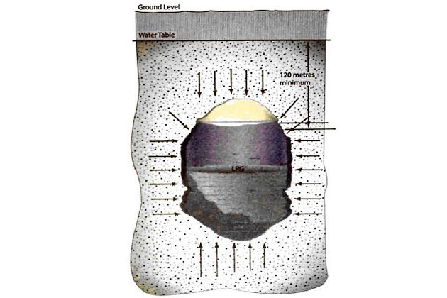
The caverns are set at such a depth below ground level that the static head of the water table is greater than the pressure of the stored product. There is, therefore, a pressure gradient towards the inside of the cavern and so leakage of product to the rock strata is avoided.
Ground water inflow is collected in a water pit on the cavern floor and then pumped to the surface. The LPG is discharged from the cavern by submerged pumps. Deepwell pumps are not usually fitted due to the length of shaft that would be required.
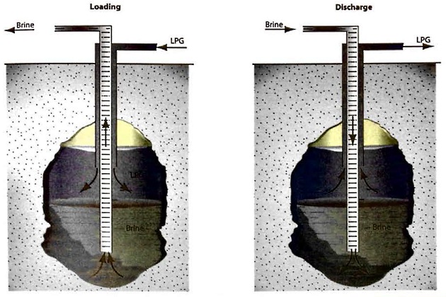
Where a cavern is leached from salt deposits the product is stored above a brine solution. On filling, LPG is pumped into the upper part of the cavern and displaces the brine. After passing through o degassing process, the brine is stored in a pit. The LPG is normally retained in the cavern by brine pressure. For delivery to ship or pipeline, LPG may be discharged either by brine displacement or by submerged pumps.
Pressurised LNG in vacuum insulated tanks
Large liquefied gas storage tanks are typically foam insulated. Smaller liquefied gas storage tanks, and specifically LNG storage, are generally stored in pressurised (Type C) vacuum insulated tanks. These tanks allow for partial filling, require no secondary barrier and allow a certain degree of pressure build-up inside the tank (compared to atmospheric type storage). In addition, they are easy to construct offsite and then install where needed. The vacuum provides excellent thermal insulation. Although not required, the external shell also provides an additional barrier in the event of leakage.
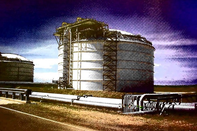
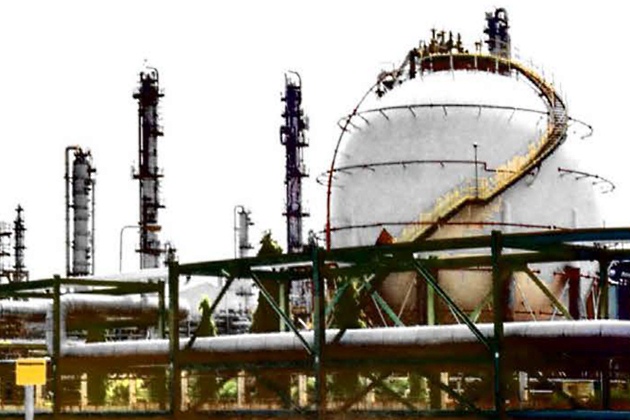
Storage in semi-pressurised spheres
Spheres for the semi-pressurised storage of liquefied gases can be Fabricated on site. Each may provide up to 5 000 tonnes of storage capacity. This type of storage usually requires vapour pressure control by means of a reliquefaction plant (see Figure 20).
Refrigerated storage at atmospheric pressure
Above-ground storage tanks
Refrigerated storage is considered economical when storing liquefied gas in quantities of more than 5 000 tonnes.
| The tanks are flat bottomed vertical cylinders. There are currently several international standards used for the design and construction of refrigerated storage tanks: | |
|---|---|
| Europe (CEN) | BS EN 1473 – “Installation and equipment for liquefied natural gas – Design of onshore installations” (Reference 2.25) |
| BS EN 14620 – “Design and manufacture of site built, vertical cylindrical, flat-bottomed steel tanks for the storage of refrigerated, liquefied gases with operating temperatures between 0 °C and -165 °C” (Reference 2.35) | |
| EEMUA Publication 207 – “Double concrete tanks for liquefied gas – Guide to design, construction and operation” (Reference 2.36) | |
| USA | NFPA 59A (Appendix Q) – “Standard for the Production, Storage, and Handling of Liquefied Natural Gas (LNG)” (Reference 2.24) |
| API 620 – “Design and construction of large, welded, low pressure storage tanks” (Reference 2.37) | |
| API 625 – “Tank systems for refrigerated liquefied gas storage” (Reference 2.38) | |
| ACI 37 6-11 – “Code Requirements for Design and Construction of Concrete Structures for the Containment of Refrigerated liquefied Gases and Commentary” (Reference 2.39) | |
| Japan | JGA RP-107 – “Recommended practice for LNG in-ground storage” (Reference 2.40) |
| JGA RP-108 – “Recommended practice for above ground storage” (Reference 2.41) | |
| Korea | KGS AC 115 – “Code for facilities, technology and inspection for manufacturing of LNG storage tanks” (Reference 2.42) |
| KGS FP451 – “Code for facilities, technology, inspection, safety diagnosis and safety assessment for producing and supplying places of wholesale gas business” (Reference 2.43) | |
Although similar in concept, there are some differences in the requirements and definitions of these codes, standards and guidelines. Tanks are designed as single, double or full containment types.
Because cargo leaking from a refrigerated storage tank is already close to atmospheric pressure, it would boil rather than flash off. Therefore, any liquid release that takes place requires heat inflow for evaporation. The source of heat is the ground on which the liquid has fallen. The larger the surface area the greater the heat inflow and so the greater the vapour generation rate. Therefore, the use of a walled bund area around a single or double containment refrigerated tank reduces the potential vapour cloud and prevents the spread of a spilled liquid.
The tanks commonly used to store gases in a fully-refrigerated state are of the following types:
Single containment – single wall tanks (for LPG)
Traditionally, refrigerated LPG was stored in single wall tanks, shown in Figure 22. There are large numbers of this tank type still in service throughout the world. Specific details of construction vary from tank to tank, but the main feature is a low temperature steel shell surrounded by insulation. The insulation is held in place by a waterproof outer cladding.
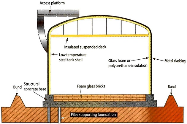
For some varieties of this tank type, additional insulation can be provided above the liquid level in the form of a suspended ceiling. Within the tank, base heating coils, or sometimes an air gap, may be fitted to avoid freezing the ground and damaging the foundations by frost heave.
Tank filling is usually through a top entry spray ring, although some designs may have a load line led to the tank bottom. Tank discharge is generally taken from the bottom via submerged pumps, although some older tank designs use side entry.
Any leakage of liquid is contained in a bunded area around the tank. Tanks of this type will normally be designed to an appropriate code that requires a bund to contain a spillage volume at least equal to the tank contents.
Single containment – double wall tanks (for LPG and LNG)
Single containment tanks are usually provided with an outer shell that surrounds the primary inner tank. Only the inner tank is then generally required to meet the low temperature requirements for product storage.
The outer shell is primarily for the retention and protection of loosely filled insulation and to contain nitrogen purge gas pressure. The outer shell is not designed to contain refrigerated liquid in the event of leakage from the inner tank, and may suffer brittle fracture if it were to come into contact with large quantities of cryogenic liquid leaking from the inner tank.
Therefore, a single containment tank typically needs to be surrounded by a bund wall or dyke to prevent uncontrolled liquid spillage. Because cargo leaking from a refrigerated storage tank is already close to atmospheric pressure, it would boil rather than flash-off. The bund wall contains any liquid leakage and its position minimises boil-off rote (BOR) by preventing liquid from spreading over a large area of worm ground.
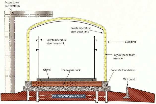
Figure 23 shows a typical double wall tank for LNG. This example shows two complete tanks with an annular gap of about 0,5 metres. The annular space may be filled with granular insulation such as perlite (see Table “Liquefied Gas Carrier TypesTypical insulation material conductivities at 20 °C“) and a nitrogen breather system is provided to accommodate volume changes in the inter-space, which may be the result of atmospheric pressure changes and inner tank expansion or contraction. A suspended roof, inside the outer tank dome, fits inside the inner tank. Here, the insulating space is filled with cargo vapour that flows freely from the main vapour space.
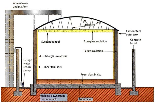
Such a tank is classified as a single containment storage system and any leakage of liquid is contained in a bunded area around the tank. Tanks of this type will normally be designed to on appropriate code that requires the bund to contain a spillage equal to or greater than the entire tank contents. Alternative versions of this design are provided with a full height concrete bund wall. This is constructed close to the tank, usually within one or 2 metres from the outer shell.
Figure 24 shows another typical double wall tank and, in this case, on elevated foundation is used to eliminate frost heave problems. There is also a complete dome cover on the inner tank to enable inner tank leakage to be detected in the nitrogen gas in the insulation space.
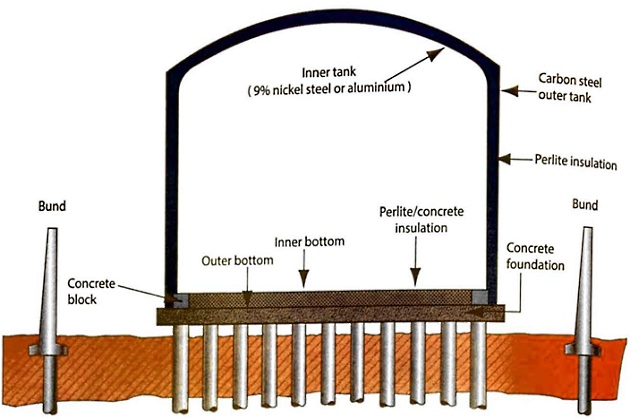
The bund wall contains any liquid leakage and its position minimises BOR by preventing liquid from spreading over a large area of warm ground.
For single containment designs, pipe penetrations below the liquid level are permitted according to US codes and regulations (NFPA 59A, 5.3.2.7 (Reference 2.24)), but under European regulations they are prohibited (BS EN 1473, 6.3.3 (Reference 2.25)).
Double containment storage tank (for LPG and LNG)
Double containment storage tanks are a development of the single wall tank. They provide increased safety margins against tank leakage by introducing an extra secondary containment.
Figure 26 illustrates this design, where the liquid is contained in an inner shell that is surrounded by an outer shell, which are both constructed of low temperature steel.
The outer shell acts in the same way as a bund and contains any liquid leakage from the inner shell. As with the single containment tanks, the secondary containment (outer shell) is generally located at a distance from the primary containment (inner tank) in order to minimise the evaporation rate of any leaked liquid.
The primary containment holds the refrigerated liquid under normal operating conditions. The secondary containment is intended to contain any leakage of the refrigerated liquid, but is not intended to contain any vapour resulting from that leakage.
For the double containment design philosophy, pipe penetrations below the liquid level are prohibited (NFPA 59A, 5.3.2.7 (Reference 2.24) and BS EN 1473, 6.3.3 (Reference 2.25)).
The mini bund, as shown in the Figure 26, is provided to contain minor leaks from pipelines valves and flanges.
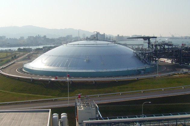
Full containment storage tanks (for LPG and LNG)
Full containment design, shown in Figure 27, is a further development of the double containment design. Both the inner tank and the outer tank are capable of independently containing the stored refrigerated liquid. The inner tank contains the refrigerated liquid under normal operating conditions. The outer roof is supported by the outer tank. The outer tank is intended to be capable of both containing the refrigerated liquid and controlling venting of any vapour resulting from a product leakage after a credible event.
Typically, the inner tank is surrounded by a low temperature steel membrane tank supported by a reinforced concrete wall. This, in turn, is backed with an earth berm to provide further assurance against both internal and external loads. This tank has a steel roof in preference to concrete. If an earth berm is not used, both the outer tank and roof are usually built with reinforced concrete. These concepts may also be applied to LNG storage tanks.
Источник: Foter.com
For the full containment design philosophy, pipe penetrations below the liquid level are prohibited (NFPA 59A, 5.3.2.7 (Reference 2.24) and BS EN 1473, 6.3.3 (Reference 2.25)).
In-ground storage tanks for LNG
In-ground tanks are a popular option for storing LNG, particularly in populated areas. They provide:
- High integrity storage with virtually no risk of spillage;
- high seismic protection against earthquakes;
- minimal visual impact on the environment.
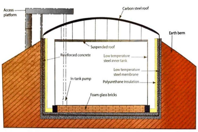
The main features of in-ground LNG storage tanks are illustrated in Figure 29.
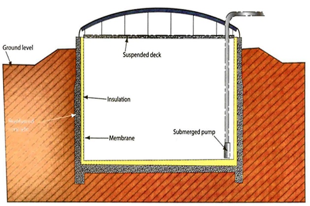
Primary containment is by a stainless steel membrane supported by rigid polyurethane foam insulation. This, in turn, is supported within a reinforced concrete caisson. The roof is a dome shaped carbon steel structure supporting a suspended deck with glass wool insulation. The roof of the tank is above ground.
Construction materials and design
The materials of construction for refrigerated tanks depend on the storage temperature. Carbon steels, or in some cases nickel alloy steels, are used for LPG tanks but, for lower temperatures, alternative materials such as 9 % nickel steel, austenitic stainless steel, invar, aluminium alloy or pre-stressed concrete must generally be used.
The foundations for all refrigerated tanks, particularly for LNG, are typically designed to allow for, amongst other things, thermal movement of the tank, anchorage against uplift, insulation of the base and foundation settlement. A further need is to prevent ground freezing and frost heave conditions, which may lift and damage the tank. This may be achieved by the provision of an air space under the tank, as in Figure 24, or by the installation of a heating and temperature monitoring system in the foundation and in the vertical wall of in-ground tanks and tanks with an earth berm.
With the widespread use of double and full containment tanks for liquefied gas storage, the use of reinforced or pre-stressed concrete has grown. This is frequently used in the construction of the outer skin of double wall tanks. A small number of LNG tanks have been constructed where both the inner and outer walls are of pre-stressed concrete and the ACI 376 Code (Reference 2.39) and EEMUA 207 Guidelines (Reference 2.36) now exist for concrete inner tank walls.
Where refrigerated tanks are insulated externally, sealing of the insulation is necessary to prevent moisture ingress (such as rain) and subsequent freezing. Poor maintenance has been known to result in insulation collapse.
Ancillary Equipment
Pressure relief venting
Liquefied gas tanks will generally need to be fitted with pressure relief valves. In certain designs, for example in the case of refrigerated tanks, vacuum breakers are also fitted. These protect the tank against over or under pressure due to process malfunction or fire conditions. Both conventional spring loaded and pilot operated pressure relief valves are used, as described in article “Cargo equipment for gas carriers carrying LNG/LPGRelief valves for cargo tanks and pipelines” and “Cargo equipment for gas carriers carrying LNG/LPGTypes of pressure relief valves“. Relief can take place either to atmosphere or to a flare. This will depend on storage quantities, site layout and products handled. Flame arresters in vent lines are a potential cause of blockage (with consequent tank failure) and it is prudent for them to be regularly inspected and maintained.
Tank farms are usually provided with a water deluge system to give additional protection in the event of fire. Alternatively, intumescent coatings that char under fire conditions, providing substantial heat absorption and insulation, are often used.
Pipelines and valves – engineering standards and surge pressure
Pipelines and valves used in liquefied gas service are designed, installed and maintained to meet specific standards and codes of practice. This means, for example, provision for positive isolation at the inlet and outlet of all storage vessels, adequate allowance for thermal expansion and contraction in pipelines and pressure relief for liquid trapped between isolation valves.
Expansion loops are incorporated into the pipeline design to provide scope for contraction during transition from ambient to cryogenic temperatures and, conversely, for expansion from cryogenic to ambient temperatures (see Figure 32).
Sample points are normally provided with double shut-off valves. It is customary to open the primary isolation valve fully and throttle on the secondary valve. In this way, any blockage due to hydrate formation will occur at the secondary valve, leaving the primary valve free to isolate again when the blockage is cleared. This is of particular relevance for drainage connections of pressure vessels.
Shore pipeline engineering standards
Pipeline design and engineering in terminals is usually covered by standards developed jointly by the American Standards for Testing and Materials (ASTM), the American Society of Mechanical Engineers (ASME) and the American National Standards Institute (ANSI). National codes are also consulted. According to the American standards, differing design factors prevail depending on the product being handled. Petroleums have been divided into four classes: A, B, C, and D. LPG and ammonia, for example, fall into Class D, which is the category carrying the highest risk.
Pipelines that run outside terminal compounds are usually designed in accordance with ASTM/ASME standards B31.4 (Reference 2.44) and B31.8 (Reference 2.45). For the ship/shore interface, these standards may only need to be addressed by terminals when considering pipework to jetties and on the jetty itself. The standards consider population densities and provide guidance for extra precautions as pipelines traverse areas of differing population levels. They also consider practical difficulties, such as the design requirements at road crossings.
Read also: Cargo equipment for gas carriers carrying LNG/LPG
External damage is a major cause of pipeline failures and specific precautions against this may need to be addressed. For example, pipelines on jetties may need to be suitably protected against damage by vehicles.
Most pipelines within terminals are designed and engineered to the ANSI/ASME B31.3 (Reference 2.46). In addition to the general engineering aspects, as covered in B31.3, design limits such as temperature and pressure for a particular pipeline are specified in ANSI/ASME B16.5 (Reference 2.47). The standards also address maximum working conditions and provide design characteristics for pipes, flanges, fittings, reducers, gaskets and bolting. B16.5 also identifies flange pressure/temperature ratings, such as ANSI Class 150 and Class 300, either of which may be found in terminals, depending on the working pressure of the system.
Surge pressures
When a liquefied gas terminal is being designed, it is common for the proposed pipeline system to be subject to hydraulic surge analysis.
Operators, designers and engineers will commonly need to:
- Recognise the potential hazards of surge pressure;
- understand the factors that affect surge pressure;
- review the engineering and operating procedures of their cargo transfer system;
- appreciate aspects of surge pressure control on the other side of the ship/shore interface for mutual understanding of safe transfer procedures;
- appreciate that surge pressures can be mitigated by incorporating a linked ship/shore ESD system.
Surge pressure limits are covered by the establishment of the maximum allowable incidental pressure (MAIP). In principle, the maximum and minimum pressures that can be developed under worst case surge conditions during normal operation will not exceed the design pressure of ship and terminal cargo transfer systems.
The inherent risks associated with surge apply to all liquefied gases.
Pipe forces and rates of pressure change can be high in LNG or LPG systems due to vapour pocket formation and collapse. LNG or LPG loading and offloading systems typically operate very close to the vapour pressure. At the operating temperature of LNG systems the vapour pressure changes significantly with temperature, so a temperature rise of just a few degrees can lead to significant vapour formation within the system, particularly in the higher elevation sections, typically at the tanks and MLAs. LNG or LPG systems are, therefore, particularly prone to vapour formation and collapse issues, although the risks are higher in LNG systems. This is because LNG is pumped at much lower temperatures and is, therefore, prone to more rapid temperature rises and vapour formation if, for example, there is a deficiency in the pipe insulation or if LNG is left to rest in the pipeline for extended time periods.
The change in velocity that is generated when an LNG vapour pocket returns to a liquid state can be very high, and occurs almost instantaneously, as LNG is essentially a very pure fluid (over 95 % methane). This, in turn, generates very high out of balance pipe loads as the high pressure waves caused by the vapour pocket collapsing are transferred through the system.
The momentum change caused by the pressure surge also results in forces acting on the pipe supports and can lead to potential pipe movement. Typically, the hydraulic surge analysis will account for the pipe forces in the design, as there is often a balance between minimising surge pressures while ensuring that the pipe is sufficiently supported. The majority of surge incidents on liquefied gas systems occur due to pipe movement or flange separation, resulting from inadequately supported pipes rather than high pressure pipe bursts.
Methods of limiting high surge pressures include the ESD system requiring specific valve closing times and the provision of special fast response pressure relief systems. In addition, mountings for pipelines on the jetty will typically be engineered to protect the jetty structure from shock loads.
While many publications are available on the subject, including SIGTTO’s “Guidelines for the Alleviation of Excessive Surge Pressures on ESD” (Reference 2.17), they support the conclusion that careful consideration will generally need to be given to surge pressures to help to prevent problems.
Excessive surge pressures on ESD can be minimised if the ship and the terminal ESD systems are linked to act in combination such that, irrespective of whether ESD is initiated o n the ship or on shore, the terminal will shut down during loading of cargo and the ship will shut down on discharging prior to the ESD valves closing.
Similarly, during discharge operations, it is common for the ship’s ESD valves to close before the terminal valves. As the IGC Code requires that ship cargo pumps are stopped on initiation of ESD, the surge pressures in the ship’s pipelines should generally be limited to within their design pressure.
While the practice of tripping the shore transfer pumps at initiation of the ESD is intended to reduce the peak surge pressures, it can significantly increase the pipe forces in the system, especially in the case of long pipeline lengths from the shore storage tank to the gas carrier.
Pipe forces are generated as a result of pressure differentials along pipes, ie rate of change of pressure affects pipe loads. Therefore, as the low pressure wave generated by the pumps tripping meets the high pressure wave caused by the MLA ESD valves closing, significant pipe forces are created in the mid pipe sections.
Surge pressures can be limited at the design stage by careful selection of line diameter, system rating, valve closure times and ESD operations. Other constraints often prevent optimisation, so other methods may need to be selected to ensure high integrity protection against surge pressures.
Bursting disks and surge drums
The danger of surge pressure generation may be greatly minimised by providing surge pressure relief of the loading pump and loading line. There are various means of achieving this, such as use of a surge relief line to a storage tank at the pump discharge. Another system is outlined in Figure 33, where surge protection is provided by bursting disks.
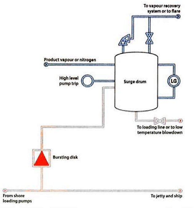
Liquid released is collected in a surge drum that is held under a nitrogen or product vapour blanket. Liquid collected is normally returned to the loading line or drained to blowdown, and vapours are usually vented to the vapour recovery system or to a flare.
Modification of existing LNG terminals for export
Many LNG import terminals have been modified to provide the additional capability to export LNG, acting, in effect, as transhipment facilities. A number of technical considerations may need to be taken into account when adapting a receiving terminal into an export terminal. A proper risk assessment may need to be carried out on the various systems in the terminal, which will include but not be limited to:
- Direction of non-return valves and other pipeline considerations;
- separate surge analyses model both the loading and unloading modes with a view to minimising any sudden potential pressure loads on the jetty structure, piping and the entire terminal system;
- upgrades to LNG transfer pumps installed in receiving terminal shore tanks, as these pumps are sized for the amount of LNG to be transferred to the terminal’s vaporisers to satisfy terminal gas sendout specifications and may be insufficient for loading a gas carrier;
- cargo transfer ESD functions (both LNG transfer pump shutdown and timing of ESD valves);
- return vapour handling;
- simultaneous operations (for example, load two ships concurrently or export/import concurrently);
- shore tank BOG management.
A number of terminals are now also used for STS loading across the dock, through the jetty pipelines, which will often require the ESD facilities to be modified.
Pumps, compressors and heat exchangers
Within terminals, centrifugal pumps are used for pumping operations when loading ships. These pumps may be inside or outside of the tank and are usually of the following types:
- Deepwell pumps;
- vertical in-line pumps;
- horizontal foot mounted pumps;
- submerged pumps within the tank.
Compressors for LPG terminal refrigeration are of a similar design to those outlined in article “Liquefied Petroleum Gas Reliquefaction Plant and Boil-Off ControlLPG Reliquefaction Plant and Boil-Off Control” for LPG ship reliquefaction systems but, generally, they have considerably greater capacity so that they can handle ship discharge or production run-down rates. A separate, smaller capacity, compressor is provided to handle boil-off vapours from within the shore tanks between loadings. This boil-off will usually be generated from heat flow through the tank insulation.
Product condensers are either air cooled or water cooled, depending on economics and environmental aspects. Other heat exchangers may include units for warming refrigerated cargoes to load fully-pressurised ships. This equipment is often heated with glycol/water systems. The basic design of this equipment is very similar to that shown in article “Cargo equipment for gas carriers carrying LNG/LPGThe Ships – Cargo Equipment“.
At some refrigerated terminals it is common practice to receive refrigerated cargoes and, subsequently, to back-load fully-pressurised ships. To facilitate loading operations cargo heaters are often fitted in the terminal loading lines. These heaters are shell and tube design and seawater may be used as the heating medium. To carry out such operations without terminal heat exchangers requires the ship to be fitted with its own cargo heater of a similar design. The basic design of this equipment is very similar to that shown in article “Cargo equipment for gas carriers carrying LNG/LPGThe Ships – Cargo Equipment“.
Figure 34 shows a typical simplified LPG terminal pipeline diagram. It includes tankage, a reliquefaction plant and export pumps.
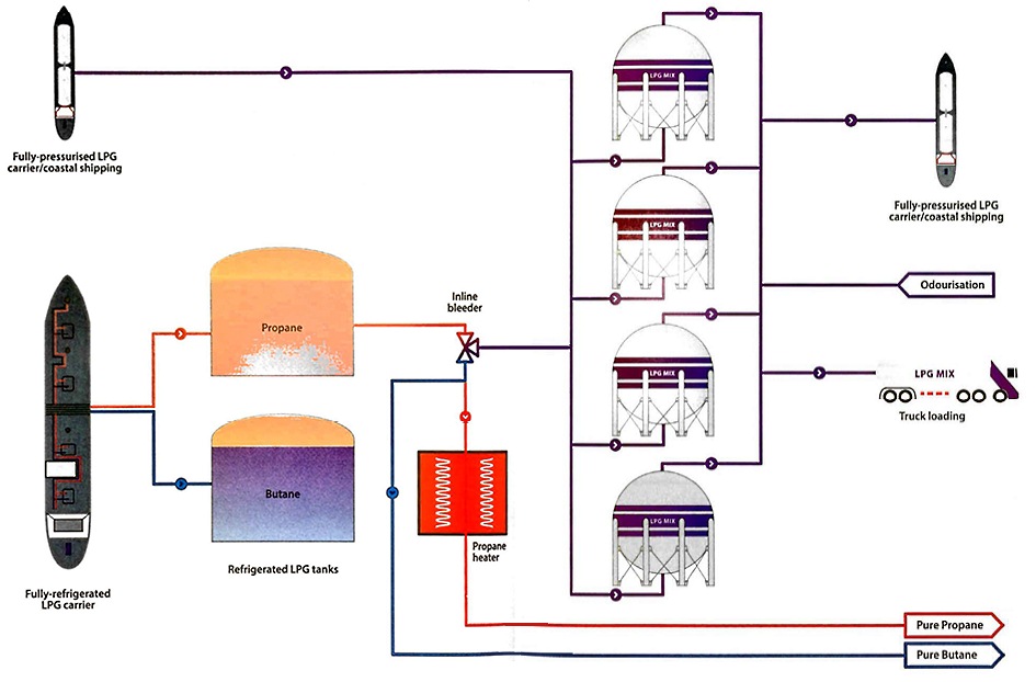
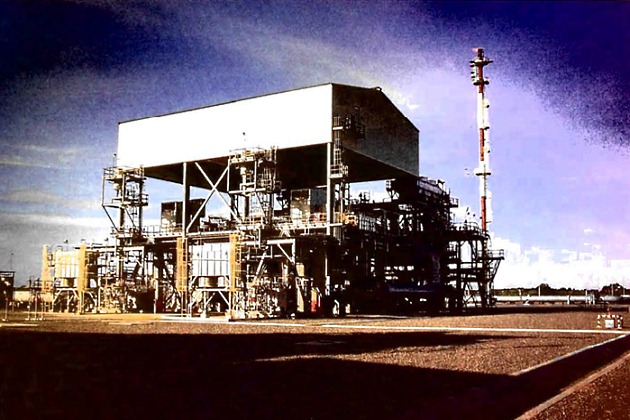
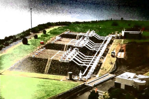
Figure 35 shows a typical simplified LNG receiving terminal.
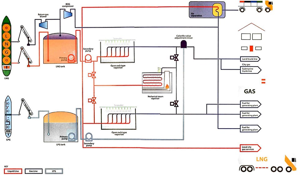
This terminal utilises the gas in two ways:
- Gas is sent out to domestic and business consumers via the distribution main;
- there is a direct connection to on adjacent electric power station.
Gas vaporisation can be achieved by:
- Natural boil-off;
- two types of vaporiser (open rock-type heated by seawater and submerged combustion type heated by gas flame);
- utilisation of cold energy in on adjacent air separation plant.
Other features of the typical LNG receiving terminal are:
- LNG is pumped from the in-ground storage tanks using submerged pumps;
- the pressure is raised to send out pressure by a booster pump that is positioned before the vaporisers;
- send-out gas is odorised and its calorific value is adjusted by injection of nitrogen or propane before leaving the plant.
Terminals utilise the energy released by vaporisation in other ways, such as by operating food freezer plants or operating direct expansion cryogenic generators to produce electricity.
Instrumentation
Product metering
The quantity of liquefied gas loaded onto a gas carrier can be determined by conventional tank gouging (ship and shore where appropriate).
Alternatively, the volumes transferred can be monitored by flow meter. It should be noted, however, that where vapours are returned to the tank being discharged, the quantity of such vapours will also be taken into account in the cargo calculation.
There are five types of metering systems in regular use at liquefied gas terminals:
- Positive displacement meters operating in a similar manner to positive displacement pumps.
- Turbine meters, where the rotation of the blades is proportional to the flow.
- Coriolis metering, where the fluid is passed through a vibrating U-tube, the mass of the gas flow being determined from the twisting of the U-tube caused by the Coriolis effect.
- Ultrasonic metering, where the volumetric flow rate can be determined. These meters are normally used for the measurement of vapour quantity.
- Vortex meter, which may be thought of as on obstruction within the pipe that causes vortices to be generated on each side of the obstruction.
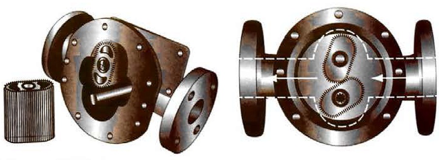
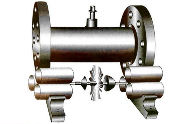
1 Positive displacement meter
Figure 36 shows a typical positive displacement meter. The meter operates on the same principle as a positive displacement pump, with the number of revolutions of the meter proportional to the volume of fluid passed.
2 Turbine meter
Figure 37 shows a typical turbine meter. Here, the speed of rotation of the turbine is proportional to the flow.
3 Coriolis mass flow meter
The Coriolis mass flow meter has the advantages of a high accuracy and direct mass flow metering without any moving parts. The measurement principle is based on the controlled generation of Coriolis forces. These forces are always present in systems when both transitional (straight line) and rotational (revolving) movements occur simultaneously. This principle has been adapted so that on oscillation replaces the rotational movements. Two parallel measuring pipes, with fluid flowing through them, are made to oscillate in antiphase so that they act like a tuning fork. When mass is flowing through there is a phase shift between the inlet and the outlet. As the mass flow increases the phase difference also increases. This phase shift is determined using electrodynamic sensors at the inlet and outlet. The measurement principle operates independently of:
- temperature,
- pressure,
- viscosity,
- conductivity or flow profile.
4 Ultrasonic meter
The measurement of vapour quantity should not be ignored. If the liquid is metered during ship loading, vapour return, if used, may also be metered. Ultrasonic meters are generally considered to offer the best possibility, mainly because they can cope with the wide range of flow rates typically found in vapour return lines. The ultrasonic meter measures the time of flight of a sound signal passing diagonally across the pipe. Times in the direction of the fluid flow and against it are required to be able to determine flow rate. These meters also require no prover and give no obstruction to the flow. They are often not calibrated since their performance can be determined from their installation, although with a higher level of uncertainty than could be expected with liquid metering. However, this does not have a major effect on the overall measurement uncertainty since the liquid mass will usually be much greater than the vapour mass.
5 Vortex meter
The principle of this meter is utilisation of the same forces that cause a flag to flap on a flag pole as it moves from side to side with the wind generated vortices.
By counting the vortices, fluid flow rate may be determined quite accurately. This meter has two advantages over the turbine meter. First, it contains no moving parts and so needs no prover and, second, it is significantly cheaper.
Proving loops
When using some types of meter, it is necessary to be able to calibrate the installation. The usual way to calibrate a flow meter for liquefied gas is to pass a quantity of liquid through a prover loop. The common arrangement for terminal metering is to have a prover loop of accurately known volume, within which there is a sphere. Figure 38 shows a typical prover loop arrangement. The sphere in the prover is designed to have a very close fit and is moved through the system by the flowing liquid. Sensors installed at the inlet and the outlet of the prover give a signal as the sphere passes. In the time taken for the sphere to pass from inlet to outlet sensor, the volume measured by the flow meter is electronically recorded. Because the volume of the prover loop is accurately known a direct calibration of the meter is possible.
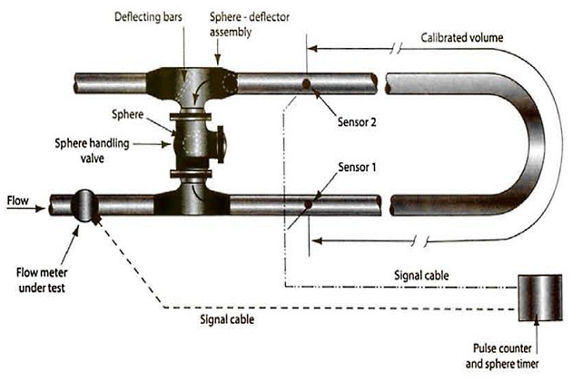
This type of prover is not to be used under refrigerated conditions because the sphere becomes hard at low temperatures. For refrigerated products a piston prover will commonly be used, with a metal piston that has low temperature seal materials replacing the sphere.
Pressure, temperature and level instrumentation
The same types of primary measurement devices for onboard instrumentation, as described in article “Cargo equipment for gas carriers carrying LNG/LPGThe Ships – Cargo Equipment“, are found in terminals.