This article describes essential operations for a LNG vessels, like drying and inerting cargo tanks, gassing-up and cooling down, load an unload liquefied gas.
- Typical Trading Cycle for a Modern LNG Carrier
- Nitrogen Purging of the Insulation Space
- Drying of Cargo Tanks
- Inerting Cargo Tanks
- Gassing-up Cargo Tanks
- Cooling Down Cargo Tanks
- Loading
- Loaded Passage
- LNG Unloading (Discharge)
- Ballast Voyage in Service – Return to Load Port
- Stripping (at Discharge Port Prior to Gas Freeing)
- Warming Up the Cargo Tanks
- Inerting of the Cargo Tanks
- Aeration of the Cargo Tanks
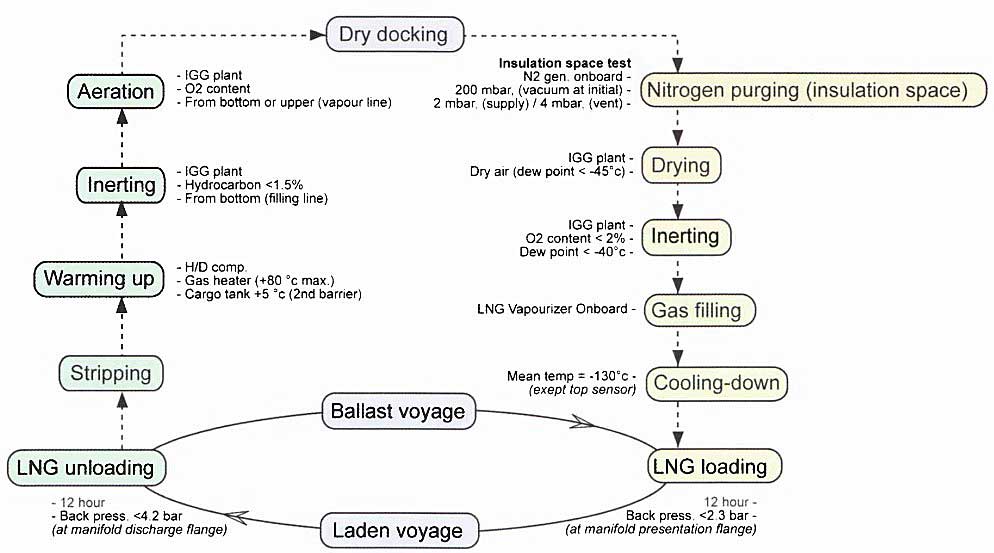
Typical Trading Cycle for a Modern LNG Carrier
The diagram below shows the typical cycle of trading pattern for a modern LNG carrier. These notes are a summary of the operations on board an LNG carrier, starting from the dry-docking stage.
Nitrogen Purging of the Insulation Space
After a new-build vessel enters service or leaves dry-dock, the humid air at atmospheric temperature in the insulation space is replaced with nitrogen (N2) before operations to prepare the cargo tanks for loading begins.
This is achieved using vacuum pumps to draw a partial vacuum on the insulation space and then removing the vacuum through the introduction of N2.
The procedure is continued until the O2 content in the insulation space is less than 2 % and the dew point is at minus 25 °C.
Drying of Cargo Tanks
On entering service after construction or a dry-dock repair period, the cargo tanks will contain humid air and must therefore be dried to prevent the formation of ice when the tanks are cooled with LNG that is at -161,5 °C.
On a 4 tank membrane vessel of 140 000 m3 it will take app. 20 hrs to dry all the tanks to a dew point of -25 °C.
Dry air from the inert gas plant is introduced to the bottom of the cargo tanks using the loading lines. It is then vented from the tank dome to the mast riser.
Inerting Cargo Tanks
(see also Cargo Handling Systems and Specialised Equipment on LNG LPG Carriers“Inert Gas System”)
Inerting takes place immediately after the “drying” stage.
The inert gas generator is used across all the tanks to reduce the O2 level to a typical value of 2 % and the dew point to -45 °C or colder.
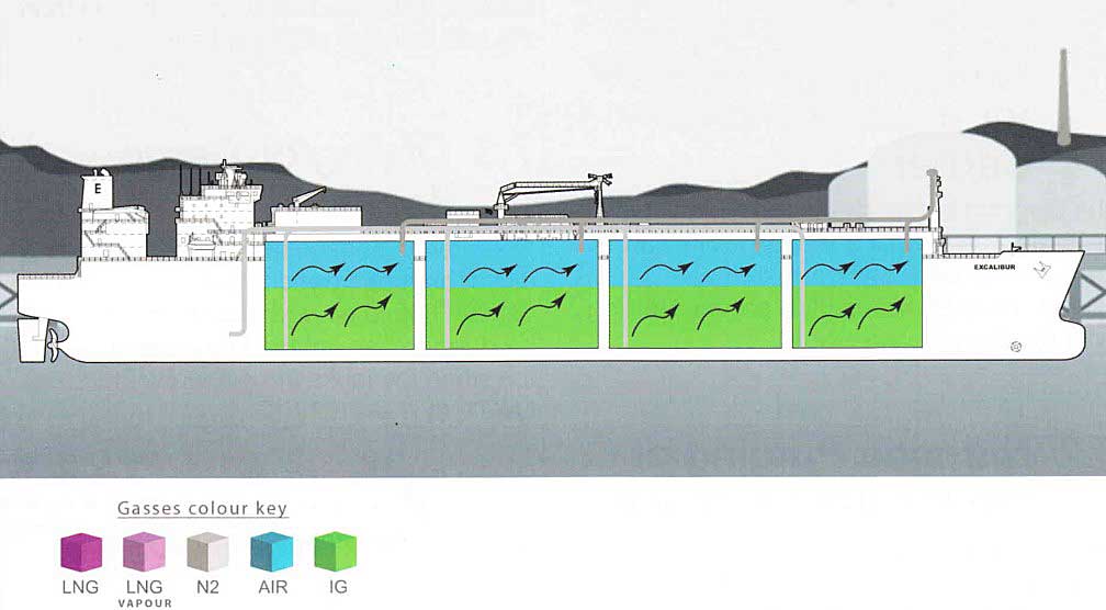
Line set-up and the introduction of inert gas is the same as for “drying”.
In addition to the cargo tanks, the following equipment must also be inerted:
- Gas heaters;
- Forcing vapouriser;
- LNG cargo vapouriser;
- LD and HD compressors;
- Spray header;
- Spray pumps;
- Spray rail;
- Cargo pumps;
- Cargo discharge lines;
- Manifolds;
- Gas header;
- Tank gauging columns;
- Instrumentation boxes;
- Fuel gas supply line to the E/R.
Inerting could be done using N2 but this is generally avoided because of the cost implications. However, it should be noted that combustion generated inert gas contains approximately 15 % CO2, which will freeze at -56 °C and can produce a white powder that can block valves and filters and spray nozzles.
CO2 freezes at -56 °C.
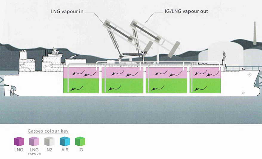
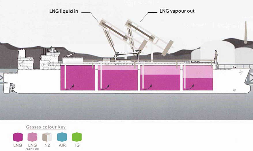
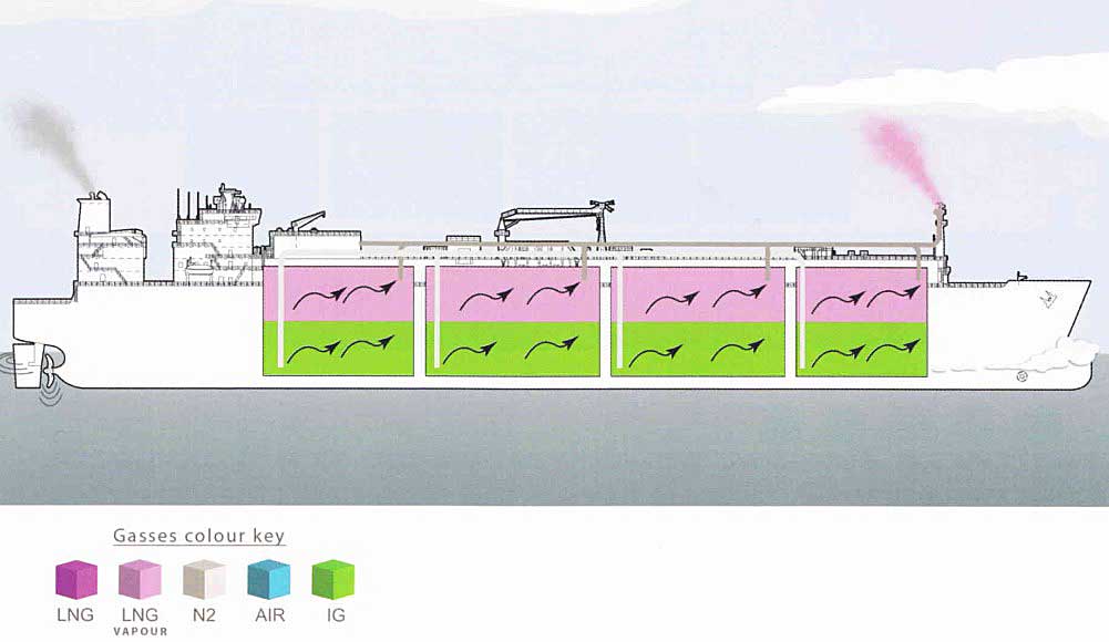
Gassing-up Cargo Tanks
After the cargo tanks have been inerted, they are purged at the load port with warm LNG vapour. This helps to remove the gases such as CO2 that could freeze at the cryogenic temperatures of the LNG. This stage is commonly known as “Purge Drying”.
LNG liquid is loaded from the shore to the LNG vapouriser and then warm LNG vapour; at approximately +20/+25 °C, is introduced to the top of the tank. This creates an interface between the LNG vapour and the inert gas in the tank.
The HD Compressors are not used when there is sufficient back pressure from the shore as they can create an undesirable turbulence in the tank.
The inert gas is expelled from the tank by “displacement” via the loading lines and is vented to atmosphere from the for’d mast riser. The operation is continued until a gas reading of 5 % methane (CH4) by volume is achieved at the mast riser. When this occurs, the HD compressors may be lined up to transfer the vapours ashore.
On a 4 tank membrane vessel of 140 000 m3, it will take approx. 20 hrs and 425 m3 of LNG for gassing-up.
The gassing-up operation is considered complete when the CH4 content exceeds 88 % in each cargo tank. Note that most LNG cargoes consist of approximately 95 % methane (CH4).
Cooling Down Cargo Tanks
Cool-down is the process that brings the Liquefied Natural Gas and Liquefied Petroleum Gas Cargo Containment Systemcargo containment system to a temperature that does not cause excessive boil-off during loading and prevents thermal shock to the primary containment system.
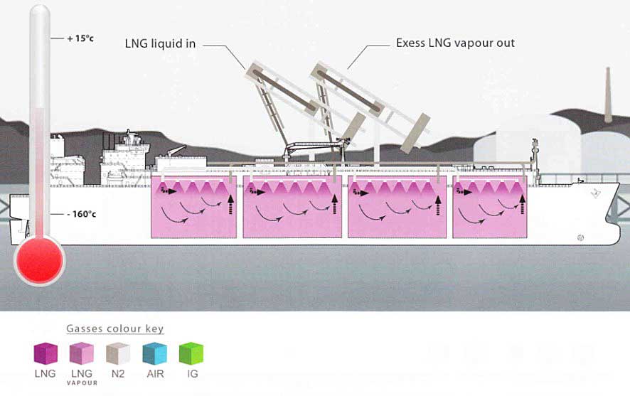
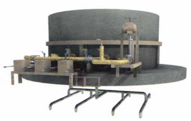
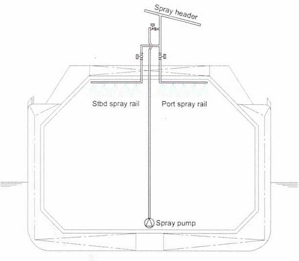
The cool-down operation is achieved by introducing LNG through the spray header and cool-down grids at the top of each tank. The liquid LNG will vapourise at the sprays and cold LNG vapour will enter the tanks.
On membrane vessels cool-down is continued until -130 °C is achieved.
On Moss Rosenberg vessels cool-down is continued until -115 °C is achieved.
The cool-down rate must never exceed 9 °C per hour on a Moss Rosenberg ship. For a ship/shore bonding cable to be effective it would need to be 12” diameter copper.
As examples of how long cool-down takes:
- 140 000 m3 membrane, approximately 10 hours from +40 °C to -130 °C;
- 135 000 m3 Moss Rosenberg, approximately 24 hours from +40 °C to -115 °C.
Any excess vapour generated is returned to the terminal, using the HD compressors, via the vapour line.
Loading
After the loading arms are connected, they are purged with N2 and leak tests are conducted using soapy water. When the loading arm is purged, the O2 level must be less than 1 % and the dew point colder than -50 °C.
After the loading arm is connected a test of the ESDS will be initiated. The closure time of the remote actuated valves will be timed to verify that they close within 30 seconds.
The ship will normally be able to burn boil-off gas throughout the loading operation.
Complete the ship/shore safety check-list with the terminal representative (as in the Terminal Operations section of this book).
Before beginning the load, the ship will request that the VRL is opened and then begin returning vapour ashore.
The ship will prepare all the lines, crossovers, manifolds, spray rails for cool-down. The terminal will begin the cool-down, gradually cooling the lines on the jetty and then the ship.
When loading commences watch for frosting of the cargo pipes on deck.
In the event of a large leak, cargo must be stopped and the area flooded with sea water to prevent cold brittle fracture of the steel deck.
The terminal will normally confirm that they have completed cool-down before the ship. When the ship has completed cool-down (normally when the liquid header is approx. -157 °C), set the tank loading valves and ask the terminal to commence loading at the agreed rates.
As the tank pressures rise, start the first HD compressor to return vapour ashore.
When the ship is coping with the levels of boil-off gas created and the hold space pressure is satisfactory, it will request the terminal to increase the loading rate as agreed.
Read also: The Gases and Their Properties, Liquefaction Process (LNG/LPG)
As the pressure rises and the creation of cargo boil-off exceeds the capacity of the HD compressor in operation, start the second unit.
When the maximum load rate is achieved, continue to monitor the loading and concurrent ballast operation as per the cargo plan. Take care throughout to ensure that a level difference does not occur on either side of the tank.
Give one-hour notice to the terminal prior to topping-off.
Throughout the loading operation the tanks will be staggered to allow for a time difference between each of the tanks finishing. This is known as “topping-off”.
IGC Code stipulates 98 % by volume.
However, flag and class approval allows, on a case by case basis, approvals for loading to the following levels:
Membrane LNG Carriers = 98,5 % (due to boil-off allowance en route).
Moss Rosenberg LNG Carriers = 98,8 % (due to tank design and boil-off allowance en route).
Throughout the topping-off procedure the loading rate will be reduced, as per the cargo plan, and the liquid valves on the tank secured. Stop the first HD compressor as the pressure begins to rapidly decrease.
Before the last tank is topped-off, stop the second HD Compressor and start the LD compressor for ER fuel gas burning.
The last tank must be stopped while leaving sufficient space to allow for draining of all lines to that tank.
When all lines are drained, close the remotely actuated manifold valves.
The loading arms will now be pressurised with N2 and purged of hydrocarbons. This will continue until the expelled vapour has a CH4 content of less than 1 % by volume.
The loading arms are released and the ship prepared for sea.
Loaded Passage
The movement of the ship on passage and the ingress of external heat through the tank insulation creates cargo boil-off. This can account for 0,10-0,15 % of the ship’s cargo volume per day.
Average daily boil off = 0,15 % per day.
The cargo boil-off is burned in the ships boilers, CH4 being the dominant component of LNG, and it is the only cargo permitted to be used as fuel in this way. CH4 vapour is lighter than air when warmed to ambient temperatures whereas LNG vapours are heavier than air. In the event of leakage, CH4 tends to be dispersed more easily.
LNG is not reliquefied on board as the plant and power requirement is too complex and costly.
If it was not possible to use the boil-off as fuel gas, or the boilers could not keep up with the cargo boil-off rate, as a last resort the tanks can be vented to relieve pressure-up the forward mast riser.
Boil-off vapours used as fuel are handled using the “Low Duty” (LD) compressor. The LD compressor takes vapour from the tanks and discharges it, through a cargo or gas heater into the engine-room fuel system. The boil-off rates during loaded passage will vary with changes in atmospheric and tank pressures. Interbarrier space pressures must be monitored.
LNG is not reliquefied on board as the plant and power requirement is too complex and costly.
Normally the compressors used on LNG vessels have N2 pressurised shaft seals, so an adequate N2 supply must be available at all times when the compressor is running. As with LPG compressors, care must be taken to avoid liquid being carried into the LD compressor via the vapour suction line.

It is necessary to ensure that pipelines supplying CH4 vapours to the machinery spaces are protected by an annular pipe with N2 atmosphere and are purged with inert gas both before and after gas burning operations.
On no account should tank pressures fall below atmospheric pressure.
As a precautionary measure, it is normal practice on LNG vessels to carry out visual cold spot inspections of cargo tank surrounds. Cold spot inspections of the hold spaces must adhere to the procedures for entry into enclosed spaces.
The cargo must be delivered within the agreed “Sale&Purchase” agreement, which commonly includes a maximum delivery temperature (colder than minus 158,8 °C) and a range of allowable vapour pressures.
Checks in preparation for the discharge port will start several days before arrival.
LNG Unloading (Discharge)
Liquid and vapour arms are connected. The vapour arm allows the shore to return LNG vapour to the ship.
The discharge arms are connected, purged with N2 and tested for leaks using soapy water. While de-pressurising, the O2 level will be checked to confirm that it is below 1 % and that the dew point is confirmed to be colder than -50 °C.
Complete the ship/shore safety check-list with the terminal representative.
Immediately prior to starting the discharge, many terminals require the LNG carrier to stop E/R fuel gas burning. This may not resume until the post discharge cargo survey “after discharge” is complete.
The ship’s ESDS is tested.
After obtaining permission from the terminal to open the manifold valves, it is standard practice to test the manifold ESD valves to allow the terminal to check the closure times.
The ship will now request return gas from the shore. All lines and valves will be set. When the ship is informed that the terminal is ready for cool-down, discharge will commence.
Cool the manifold and discharge arms using the spray pump (the spray header is cross-connected to the liquid manifold).
When the cool-down is completed, some vessels use the spray pump to prime the discharge column on the first cargo pump as this avoids creating pressure surge in the lines.

The cargo pumps are started and the vessel is brought to the full discharge rate agreed with the terminal.
Cargo discharge and ballast loading is carried out as per the discharge plan. A stagger is placed between the tanks to create an interval between the finishing times of each tank.
The terminal should be advised 1 hour before the completion of cargo discharge.
Pay attention to the manufacturer’s recommendations on the minimum levels that cargo pumps can be restarted at, which is generally about 1 metre, but note that the cargo pumps on some modern vessels cannot be started below 1,8 metres of liquid cargo level.
As the pre-determined heel quantity is approached, stop the cargo pumps in each tank. When all the pumps have been stopped, the terminal will require closure of the liquid manifold only. On completion of discharge, leave one valve open on a tank to receive the cargo line draining.
When line draining is complete and the liquid manifold valves secure, the discharge arms are purged with N2 and must attain a hydrocarbon level of less than 1 % by volume before disconnection.
The vapour manifold will normally be left open until just before the cargo survey. After closing the vapour manifold, the vapour arm is purged in the same manner as the liquid arm.
When the cargo survey figures “after discharge” are agreed, the fuel gas supply to the E/R can be re-instated.
Ballast Voyage in Service – Return to Load Port
On the ballast passage to the loading port, the following points must be taken into account.
- Maximum use of the LNG Cargo boil-off must be achieved;
- The cold state of the vessel must be maintained;
- Cargo pressures must be maintained at the manufacturers recommended level (on a membrane vessel this is greater than 70 mbar/7 kpa).
The tanks can be maintained in a cool state by periodically spraying them with the liquid heel so that the average temperature remains below the following:
- On a membrane vessel, -130 °C;
- On a Moss Rosenberg vessel, -113 °C at the equatorial ring.
On short voyages to the load port (6-8 days) the ship may retain enough liquid heel for the tank bottom to remain covered. This removes the need to spray on the ballast passage.
Checks in preparation for the loading port will have started several days before arrival.
Stripping (at Discharge Port Prior to Gas Freeing)
The ship should trim to the maximum that the terminal permits, ~2,5 metres, and seek to achieve the maximum cargo outturn.
Caution should be exercised when running cargo pumps with a partially disrupted flow for extended periods.
Start the stripping/spray pumps and stop them before the pump loses suction. When all the pumpable cargo has been discharged, drain any remaining liquid to the allotted tank. This is assisted by blowing with N2 from the shore.
Warming Up the Cargo Tanks
A successful warm-up stage is an essential part of the inerting process. Where possible, the warm-up continues past the desired target figures as this removes the deep seated cold ingress from the tank insulation.
A successful warm-up of the cargo vapour achieves the maximum vapour density difference between the warm LNG vapour and the inert gas for the next stage, which improves the displacement effect while inerting.
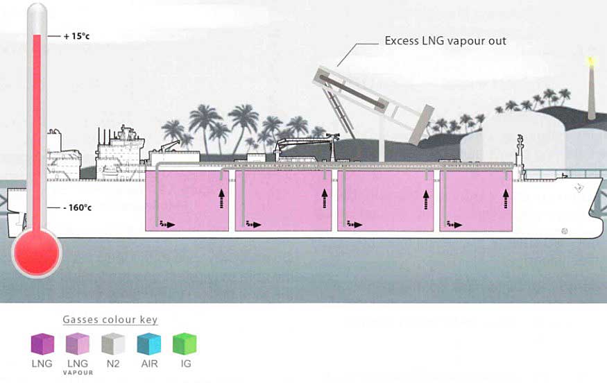
The tanks are warmed up by recirculating heated LNG vapour. The vapour is recirculated by the two HD compressors and heated in the gas heaters before introduction to the tank (1st stage 0 °C, 2nd stage 75 °C).
Watch the insulation space pressure as, when the space warms up, the N2 expands and will relieve to atmosphere.
The warm-up operation is continued until at least the following temperatures are achieved:
- On a membrane vessel, +5 °C;
- On a Moss Rosenberg vessel, -20 °C at the equatorial ring and +5 °C at the tank wall.
As examples of how long warming up takes:
- 140 000 m3 membrane, approximately 48 hours from -130 °C to +5 °C;
- 135 000 m3 Moss Rosenberg, approximately 60 hours from -115 °C to -20 °C.
Inerting of the Cargo Tanks
After the tanks have been warmed up the LNG vapour is displaced with inert gas.
Inert gas from the inert gas generator is introduced to the tanks from the bottom of the loading lines. The displaced LNG vapour is vented from the top of the tank via the forward mast riser, or ashore if the vessel is in port.
The inerting operation continues until the hydrocarbon content in the tank is reduced to 1,5 % by volume.
In addition to the cargo tanks, the Cargo Handling Systems and Specialised Equipment on LNG LPG Carriersfollowing equipment must be inerted:
- Gas heaters;
- Forcing vapouriser;
- LNG Cargo Vapouriser;
- LD and HD Compressors;
- Spray header;
- Spray pumps;
- Spray rail;
- Cargo pumps;
- Cargo discharge lines;
- Manifolds, gas header;
- Tank gauging columns;
- Instrumentation boxes;
- Fuel gas supply line to the E/R.
Typically, the operation should take 20 hours.
Aeration of the Cargo Tanks
The inert gas atmosphere in the tanks, along with all connected equipment, must now be replaced with air.
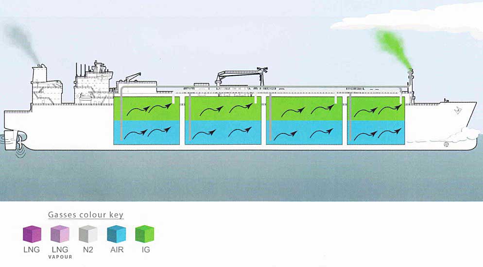
Using the inert gas generator and the dry air plant in the dry-air production mode, gas free the tanks with dry-air until a reading of 20,9 % by volume throughout is attained. This must be with 1 % LFL or less.
The cool dry-air enters the tank from the bottom of the loading lines and the inert gas is expelled through the vapour header system to the forward mast riser.
The operation will take about 20 hours.
Excellent article for begineers
tres bon article juste manque le management du nitrogène dans les espaces durant les opérations .
Thank you for your feedback! We are glad, what you find this article useful.