This article describes information about cargo handling systems, paying attention to the specialised equipment found on LNG/LPG carriers. A good understanding and appreciation of the operational capabilities and limits of this equipment is essential to ensure the smooth management of the cargo handling process.
- Cargo Piping, Pumping and Valves
- Cargo Tank Piping
- Emergency Shut-down System “ESDS”
- Pressure Surge
- Pressure Relief Valves
- Pilot-Operated Relief Valves
- Spring-Loaded Relief Valves
- Vent Arrangements
- Cargo Pumps
- Pump Performance Curves
- Running Pumps in Parallel and in Series
- Deep well Pumps
- Submerged Pumps
- Booster Pumps
- Cargo Heater
- Cargo Vapouriser
- LPG Reliquefaction Plant
- Reliquefaction Plant
- Single Stage Direct Cycle
- Two Stage Direct Cycle
- Cascade Direct Cycle
- Cargo Compressors
- Compressor Suction Liquid Separator
- Purge Gas Condenser
- Starting a Reliquefaction Plant (Cascade Cycle)
- Methanol Injection System
- Hazards of Methanol
- LNG Boil-off and Vapour Handling Systems
- Inert Gas Systems
- Inert Gas (Nitrogen) Absorption System
- Inert Gas Produced by Combustion of Gas Oil
- Electrical Equipment in Hazardous Areas
- Intrinsically Safe Equipment
- Flameproof Equipment
- Pressurised or Purged Equipment
- Increased Safety Equipment
- Instrumentation
Cargo Piping, Pumping and Valves
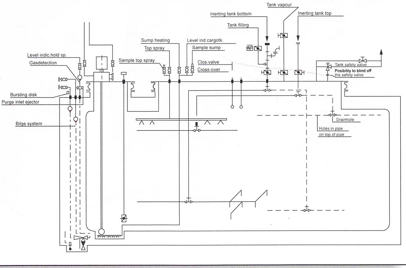
Cargo Tank Piping
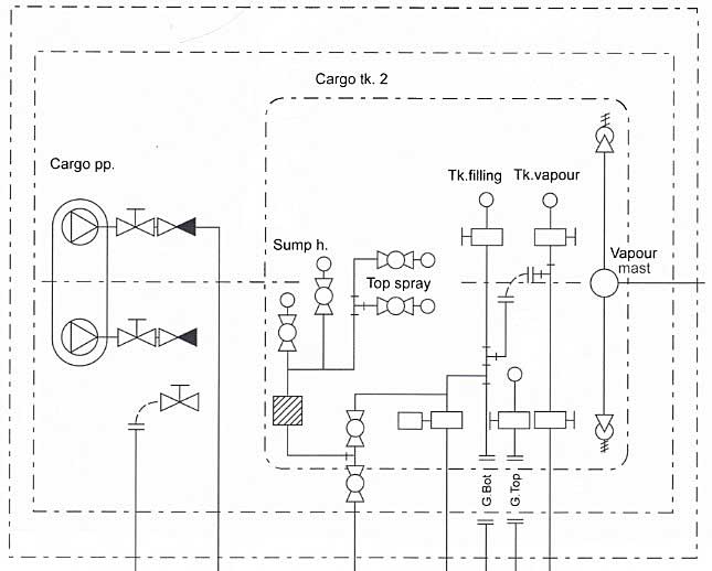
Gas carriers are normally provided with liquid and vapour manifolds amidships, each with manifold crossovers that are connected to liquid and vapour headers and with subsequent connections to each cargo tank.
The liquid loading line terminates at an opening at the bottom of the cargo tank. The vapour line is taken from the top of each cargo tank. Both the liquid and vapour lines enter the tank through the cargo tank dome.
A header is a pipeline running along the length of the main deck.
On semi-refrigerated and fully-refrigerated LPG ships, a connection from the vapour header goes to the cargo compressor room to allow for reliquefaction of the cargo boil-off and all displaced vapours.
On LNG Carriers, cargo boil-off, is taken to the engine room using the Low Duty (LD) compressors. This is burned as fuel gas in the ship’s boilers.
On LPG Carriers, a condensate header returns any reliquefied cargo (i. e. cargo condensate) back to the cargo tanks. From here it is distributed via a series of internal tank spray rails.
Cargo pipework is not allowed beneath the main deck level on gas carriers so all pipework connections to the tanks must enter through the tank dome that penetrates the deck. This design feature is to prevent the hull filling with gas or vapour in the event of a grounding or collision.
Cargo that has been reliquefied is termed “condensate”.
Vapour relief valves are fitted on the tank domes. These relieve to the mast risers whose height and distance from the accommodation are specified in the IGC Code.
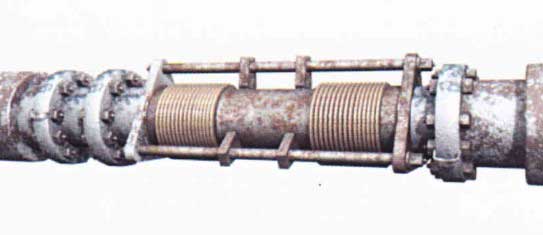
Cargo pipework must allow for thermal expansion and contraction. This is achieved using expansion bellows, fabricated expansion loops or, where appropriate, by using the natural geometry of the pipework installation. Where expansion bellows are used in a pipework section, it is important not to interfere with pipework supports as they form an integral part of the bellows installation.
On LNG ships “compressor” typically refers to a “vapour blower”.
Removable “spool” pieces are used in pipelines to inter-connect sections of line for special operational reasons, such as using the inert gas plant or ensuring segregation of incompatible cargoes.
The IGC Code requirements for isolating valves on gas carriers stipulate that cargo tanks with a Maximum Allowable Relief Valve Setting (MARVS) greater than 0,7 kg/cm2 (Type C cargo tanks) and all main and liquid/vapour connections (except relief valve connections) must be fitted with a double valve arrangement. This must consist of a manually operated screw-down valve that has a remotely operated isolation valve in series with it.
For Type “A” and “B” cargo tanks, where the MARVS is less than 0,7 kg/cm2 barg, the IGC Code makes a provision for remotely actuated single shut-off valves for the liquid and vapour connections, although they must
also be capable of local manual operation.

Remotely operated emergency shut-down valves are provided at the liquid and vapour crossovers for all gas carriers.
Emergency Shut-down System “ESDS”
1 ESDS at Sea
The emergency shut-down system ESDS (which is often pneumatically operated) is capable of operation from several locations around the ship:
- Navigational bridge;
- Cargo manifold;
- Compressor room;
- Cargo control room;
- Cargo tank dome;
- Fire control stations.
The ESDS will be activated in the event of:
- Loss of the ship’s power (blackout);
- Cargo tank high level alarm;
- Low tank pressure alarm;
- Low deck air pressure.
When activated the ESDS will:
- Remotely close the actuated valves;
- Stop the cargo pumps;
- Stop the compressors (where appropriate).
Each ESDS includes fusible elements that melt in event of fire (between 98 °C and 104 °C), initiating automatic shutdown.

2 ESDS in Port
Two types of Emergency Shut-down are classed on gas carriers:
- ESD1, activated from either the ship or the shore when in port. This deals with shutting down the ships cargo handling equipment.
- ESD2, activated by the terminal. This shuts down all the items in an ESD1, but an ESD2 also activates the “Quick Connection Disconnection Coupling” (QCDC) on the chiksan arm, creating a “dry break” from the ship and activating the quick release mooring hooks.
ESD1 = ship and shore activated.
ESD2 = shore activated.
Pressure Surge
(see also Terminal Operations for LNG or LPG Carrier after Arriving in Port“Pressure Surges”)
Creation of a pressure surge, particularly when loading cargo, is a potential consequence of activating the ESDS.
The criteria for a pressure surge varies from terminal to terminal and is proportional to the loading rate, length of the pipeline, the rate of closure of the valve and the valve characteristics. Surge pressure can cause a rupture of the loading hose or hard arm.
Remotely actuated valves on liquefied gas carriers are timed to close within 30 seconds in a controlled manner to prevent surge pressures.
On gas carriers, remote closing valves are timed to close within 30 seconds. This controlled closing rate helps to prevent pressure surges (i. e. the valve does not slam shut).
If adjustment of the valve is not possible, the terminal may reduce the loading rate to one that is deemed safe to accommodate the valve closure time.
Consultation between the ship and shore to establish the likely or known situations that can generate surge pressures must always take place when a ship comes alongside a terminal.
The types of isolation valve normally found on gas tankers are ball valves or butterfly valves, which open or close through 90° rotations. These valves are often fitted with pneumatic actuators and occasionally with hydraulic actuators.
Read also: Cargo Containment Systems of LPG and LNG
Ball valves are fitted with a means of pressure relief where a hole is normally drilled between the cavity and the downstream side of the valve.
Manifold filters are provided for loading/discharging to protect the cargo handling plant and equipment. Filters should not be by-passed and must be cleaned regularly.
Pressure Relief Valves
At least two pressure relief valves of equal capacity must be fitted to each cargo tank (except where the cargo tank is less than 20 m3 in size). Relief valves are generally pilot-operated or of the spring-loaded type.
- Relieve into the cargo tanks;
- Relieve to a mast riser fitted with liquid collecting pots.
Pilot-Operated Relief Valves
Pilot-operated relief valves may be used on Types, Layouts and Designs of the Liquefied Gas Carriers (LNG/LPG)Types “A”, “B” and “C” tanks and are required when handling refrigerated liquefied gas cargoes.
Spring-loaded relief valves are only used on Type “C” tanks when handling cargoes at ambient temperatures.
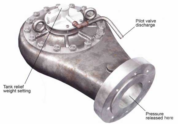
The pilot valve principle is simple. When the maximum pressure allowed in the tank is reached, the pilot valve opens and releases the counter-pressure that keeps the relief valve in a closed position.
Picture 9 shows the following:
- The connection to the tank under pressure.
- The relief valve backpressure chamber, where the pressure is normally the same as the tank pressure because of the small connection pipe.
- At equal pressure, the relief valve stays closed, as the red outer surface is bigger than the green inner surface, so the red force is bigger than the green force (Pressure = Force/Surface).
- Valve rod kept in position by the spring.
- When the tank pressure reaches the spring’s maximum setting, the valve rod lifts and the poppet valve “6” opens, releasing quickly the pressure in the chamber “2” through the pilot valve discharge “B”. The connection pipe “3” is too small to have any influence at this stage.
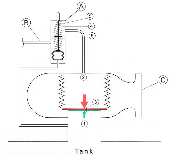
The main relief valve then opens. The tank overpressure is discharged through “C” and must be released above deck level by the vent masts.
The use of pilot-operated relief valves on Type “A” tanks ensures accurate operation at comparatively low tank pressure conditions, while their use on Type “C” tanks allows variable relief settings to be achieved using the same valve. This is done by changing the pilot spring.
Pilot operated relief valves may be fitted to Type “A”, “B” or “C” tanks.
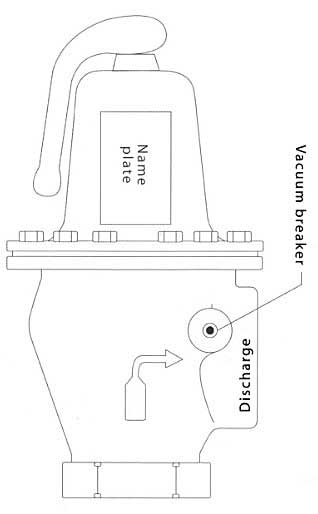
Spring-Loaded Relief Valves
A spring-loaded relief valve uses a spring to contain the tank pressure.
A spring-loaded diaphragm holds the valve closed. The manufacturer sets the spring to push down against the diaphragm at a pre-determined pressure.
Spring loaded relief valves are only to be fitted on Type “C” tanks.
The spring-loaded relief valve offers a small sized valve to protect the tank against pressure increases.
The USCG require lower tank pressure levels for Type “C” tanks than other administrations.
Many spring-loaded relief valves are fitted with a large diaphragm area to help overcome the possibility of fouling on the valve’s seat.
Vent Arrangements
Cargo tank relief valves relieve into a mast riser and so liquid drainage from the vent pipework is always allowed for.
Vent stack drains should be regularly checked to ensure that there is no accumulation of rain water or moisture in the stack. Accumulation of liquid alters the relief valve setting because of the increased back pressure. One metre of water in a column such as a mast riser would require 0,1 kg/cm2 of pressure to clear it (like a liquid pressure vacuum breaker on an oil tanker).
Regularly check the vent stack drain to check for any accumulated water or moisture in the vent stack.
Cargo Pumps
The cargo pumps fitted to gas carriers are centrifugal pumps and are either deep well or submerged.
Deep well pump motors are mounted at the tank top and submerged pumps at the tank bottom. Both are of the centrifugal type.
On a centrifugal pump, the fluid enters at the pump impeller on the axis. The rotor accelerates the liquefied gas circumferentially, compressing it against the outer rim of the impeller and generating high pressures. If the backpressure is not too high, high flow rates are achievable.
On a centrifugal pump, liquid is not sucked into the pump but flows in. If the inlet pressure falls, or liquid stops flowing in to the pump impellent cavitation will occur.
Understanding the pump’s performance is important to achieve an efficient discharge.
These may be the only pumps used. However, they can be used in series with a deck mounted booster pump (where fitted) if cargo heating is required during discharge to pressurised storage from a refrigerated vessel. Booster pumps are also centrifugal pumps that are either mounted vertically or horizontally.
Pump Performance Curves
Picture 14 shows typical performance curves for a deep well pump. You will see there are four curves displayed.

Curve A (QH Curve)
This shows the capacity of the pump as a function of the head developed by the pump. Capacity is given in terms of volumetric flow rate (Q = quantity), normally stated in m3/hr (Q). Head (H) developed by the pump is stated as “metres liquid column” (abbreviated to mlc). Adopting the parameters of volumetric flow rate and Head means that the capacity/head curve is the same for any fluid, whether it is LPG, NHs, VCM etc.
Q = quantity in m3/hr
H = head in metres liquid column (mlc).
Taking the capacity curve shown in Picture 14, this pump will deliver 100 m3/hr with a head of 115 mlc across the pump.
To convert this Head into a differential pressure reading in bars, the specific gravity of the fluid being pumped must be known. For example, at a differential Head of 115 mlc for this pump, the differential pressure across the pump, pumping ammonia at minus 33 °C (SG approx. 0,68), would be 8 kg/cm2. (i. e. [1115×0,681]/10).
Differential pressure across the pump is approximately = H x the cargo SG/10. Where the answer is in kg/cm2.
Curve B (NPSH Curve)
This shows the Net Positive Suction Head (NPSH) requirement for the pump as a function of pump capacity. The NPSH requirement at any flow rate through the pump is the positive head of fluid required at the pump suction to prevent cavitation at the pump impeller.
NPSH is the head of liquid required at the impeller to prevent cavitation.
For example, for the pump characteristic shown in Picture 14, at a capacity of 100 m3/hr the NPSH requirement is 0,5 mlc. This means that, with allow rate of 100 m3/hr; a minimum head of cargo equivalent to 0,5 metres would be required at the pump suction to prevent cavitation.
Appreciation of NPSH when pumping liquefied gas is important because the pumped is always at its boiling point. As an example, if cavitation is allowed to occur with a deep well pump, not only will it the pump impeller but also the shaft bearings will be starved of cargo for lubrication, causing bearing damage.
Cavitation can damage the pump impeller, and as the shaft bearings are liquid lubricated these can become damaged too.
Curve C
This shows the power absorbed as a function of pump capacity.
This curve is normally given for water (SG = 1) and can be converted for any fluid by multiplying by the appropriate specific gravity. Of the cargoes normally transported in gas carriers, VCM has the highest specific gravity at 0,97.
Running Pumps in Parallel and in Series
1 Running Pumps in Parallel
During gas carrier discharge, cargo tank pumps are normally run in parallel. When pumps are run in parallel their individual characteristic curves can be combined to give a capacity/head curve for 2, 3 or 4 pumps together.
Taking the pump characterised by Picture 14, the capacity head curve for running two pumps in parallel can be plotted by doubling the flow rate available at the appropriate head for a single pump, as shown in Picture 16.
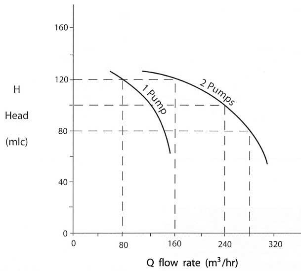
Similarly, when running three pumps in parallel, the flow rate at the appropriate developed head can be obtained by multiplying x3 the flow rate at the same head for a single pump. A series of curves can therefore be built-up from the curve characteristics of a single pump.
2 Running Pumps in Series
When pumps are run in series, the individual characteristic curves can be combined to give the appropriate curve for the series configuration.
When a refrigerated LPG/C is discharging to pressurised storage, cargo tank pumps are run in series with booster pumps.
Picture 17 shows how this can be done using, in this example, two pumps in series. This time, for each quantity of flow rate, the appropriate head developed by the pump is doubled to give the head developed by two pumps in series.

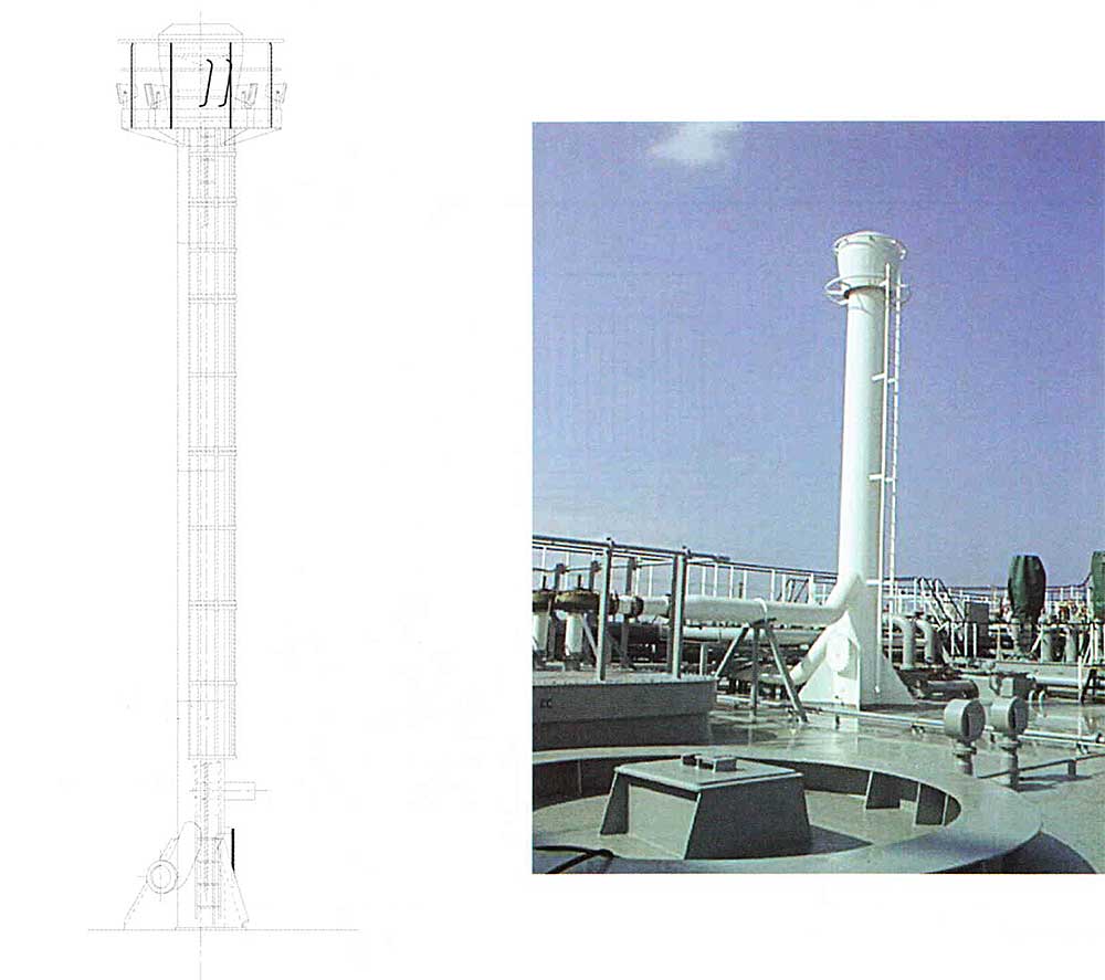
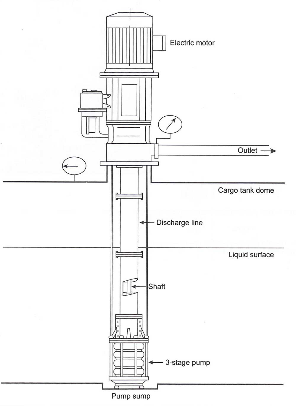
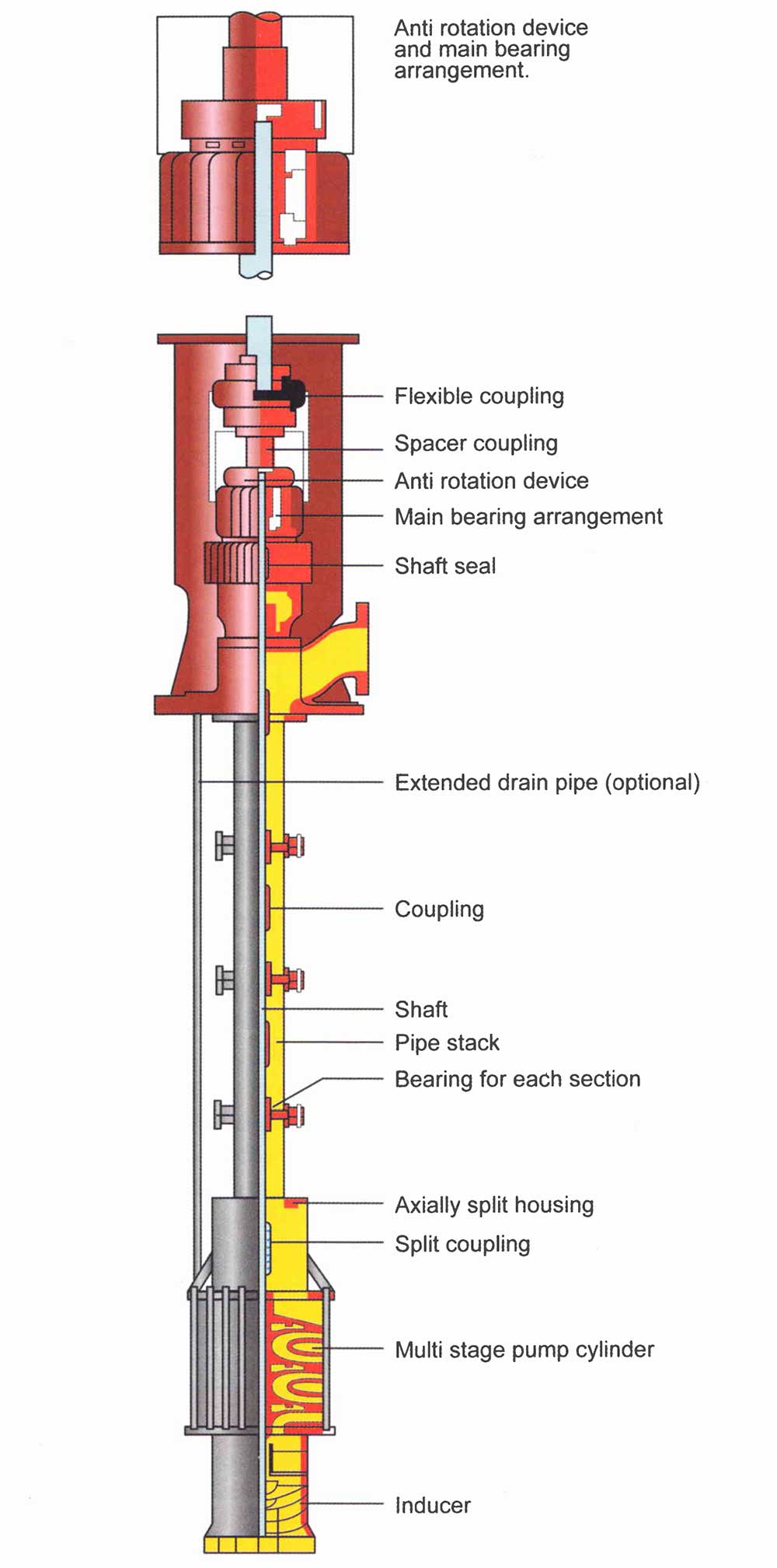
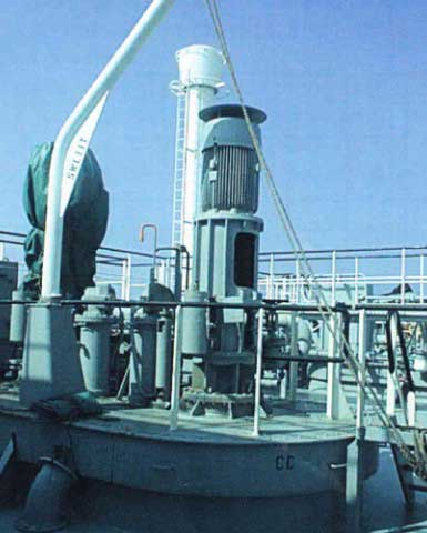
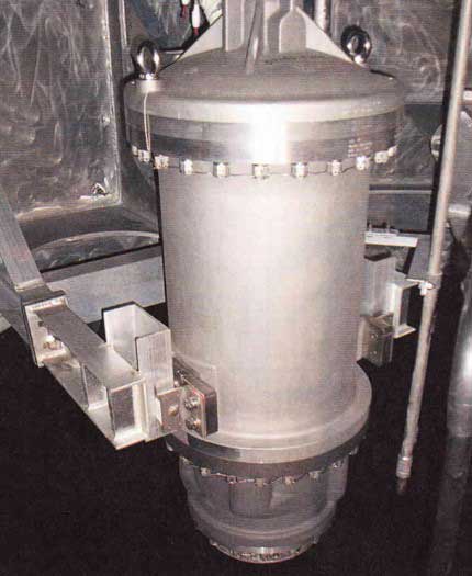
Deep well Pumps
Deep well pumps are the most common type of cargo pump. The pump is operated electrically or hydraulically by a motor mounted outside the tank. The drive shaft is aligned by carbon bearings inside the discharge piping and these bearings are, in turn, lubricated by the cargo itself.
Each time the vessel loads cargo, rotate the pump shaft by hand to ensure free movement.
The impeller assembly is mounted at the bottom of the cargo tank and will frequently comprise two or three impeller stages, together with a first stage inducer. This axial flow impeller is used to minimise the NPSH requirement of the pump. The shaft sealing arrangement consists of a double mechanical seal fitted with an oil flush. Because of the long unsupported lengths of shaft, the installation and alignment of deep well pumps is critical to the control of wear of the bearings and of heat imparted to the cooling liquid cargo, which is already at boiling point and easily vapourised.
The pump is protected with the following motor trips:
- Low motor current;
- Winding temperature;
- Overload or two phase running;
- Low differential pressure across the pump;
- Pump sealing failure.
Seizing of pump shafts on deep well pumps is a particular risk after a gas free period.
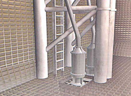
Submerged Pumps
Submerged motor pumps have traditionally been used on LNG carriers and are more likely to be used on large fully-refrigerated LPG carriers because of the problems created by long shafted deep well pumps.
Submerged pumps are cooled by the surrounding cargo.
The pump assembly and electric motor arc installed in the bottom of the cargo tank and power is supplied to the pump motor through copper or stainless steel-sheathed cables that terminate in a junction box at the cargo tank dome. The pump is lubricated and cooled-down by the surrounding cargo.
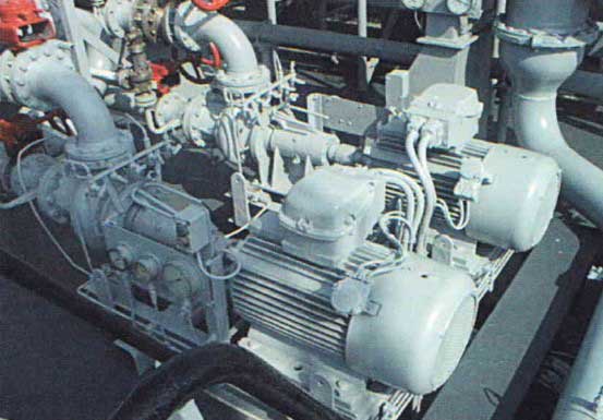
Booster Pumps
Booster pumps are centrifugal pumps and will be of the following types:
- Vertical in-line pumps, deck mounted in the appropriate discharge line and driven by an “increased safety” electric motor.
- Horizontal pumps installed in the cargo compressor room, driven through a gas tight bulkhead by an electric motor installed in the electric motor room.
Fully pressurised ships are only fitted with booster pumps.

Booster pumps are used to discharge the ship in the following circumstances:
- Where there is a high back pressure from the shore, such as when discharging into pressurised tanks ashore.
- When using the cargo heater.
If necessary, booster pumps should be circulated with cargo from the main cargo pumps and should not be started until there is sufficient cargo liquid to prevent cavitation.
Cargo Heater
The cargo heater is used when discharging
into pressurised or underground storage.
A cargo of fully-refrigerated propane at -42 °C or ammonia at -33 °C may be heated to +5 °C (this is to protect tanks or spheres ashore). The heating medium is usually seawater and the cargo heater comprises of a horizontal shell and tube heat exchanger that is deck mounted, with cargo liquid from the discharge of the booster pump on the shell side and sea water on the tube side.
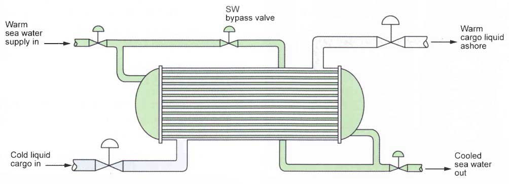
Freezing of the sea water is an obvious danger with this type of equipment and so both “low flow” and “low temperature” alarms and trips are fitted on the discharge side of the heater. Expansion bellows that allow for thermal expansion and contraction are usually necessary in the shell of the cargo heater.
Should the seawater temperature at the outlet drop (normally below 5 °C), the cargo (LPG/NH3) flow must be reduced.
The discharge temperature of the cargo at the outlet of the heater is controlled by adjusting the seawater bypass valve.
When not in use, the cargo heater must be thoroughly washed with fresh water and then drained to prevent corrosion.
Cargo Vapouriser
Liquid cargo is vapourised in the cargo vapouriser during the following operations:
- During cargo discharge, when there is no vapour return line available from the shore to prevent low vapour pressure or subsequent loss of vapour pressure in the cargo tanks which would result in a vacuum occurring.
- When gassing-up the cargo tanks if there is no vapour supply available from shore.
Vapourisers are basically vertical or horizontal shell and tube heat exchangers that use either steam, sea water or previously heated cargo as the heating source.

Steam is the most common heating medium and it may be routed from the engine room to the vapouriser. However, it is now becoming more common for the vapouriser to be capable of independent operation.
1 Operating Procedure for a Steam Heated Cargo Vapouriser
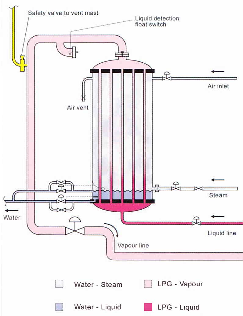
- The LPG liquid admission control valve maintains the level of liquid cargo by sensing the steam pressure.
- The LPG vapour outlet valve opens or closes according to the pressure in the vapouriser dome.
- The upper drain valve is controlled by a float-switch. It maintains the water level in the vapouriser.
- A temperature sensor controls the lower drain valve. This valve completely drains the water to avoid icing if the vapouriser is stopped. To assist in purging the water condensate the air inlet valve would be opened in this situation.
LPG Reliquefaction Plant
On semi and fully refrigerated vessels there needs to be a method of controlling the vapour pressure of the cargo within the tanks as it Increases with temperature. This is achieved by the use of a reliquefaction plant.
It is possible to cool the cargo by continually removing the vapour, an example being the practice of removing boil-off LNG vapour for use as EIR fuel gas on LNG Ships.
On fully-pressurised gas carriers (type “C” tanks), no additional means are necessary to control the vapour pressure as the tank structure is designed to withstand the maximum vapour pressures the gases might create in all normal conditions of carriage.
Semi and fully refrigerated gas carriers (LPG) are fitted with a reliquefaction plant that reliquifies the vapours produced by cargo boil-off.
Reliquefaction Plant
Reliquefaction plant of LPG carriers are of the following types:
- Direct cycle, where the cargo vapour itself undergoes a refrigeration cycle to condense it and return it to the tank.
- Indirect cycle, where an external refrigeration medium is employed to condense the cargo vapours without the cargo vapours being heated in compression. This cycle is less common and requires a very cold refrigerant so is generally used with polymerisable gases such as butadiene or VCM.
In both types, the latent heat of vapourisation, plus some superheat that the boil-off has absorbed, is removed from the boil-off vapours.
The direct cycle reliquefaction plant is found on the majority of gas carriers handling LPG and anhydrous ammonia. The manufacturers of reliquefaction plant for these cargoes have incorporated the direct cycle in different manners, but with the same main plant functions:
- Cooling down cargo tanks and related pipework before loading.
- Reliquefying evaporated cargo vapours and boil-off during loading.
- Maintenance of cargo temperature and pressure during the loaded passage.
Single Stage Direct Cycle
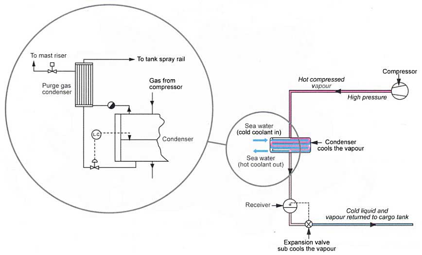
In a single stage compression reliquefaction cycle, as shown in Picture 26, the boil-off vapours from the cargo tank are drawn-off by the compressor and then compressed. This increases the pressure and temperature of the vapour; allowing it to be condensed against sea water in the condenser.
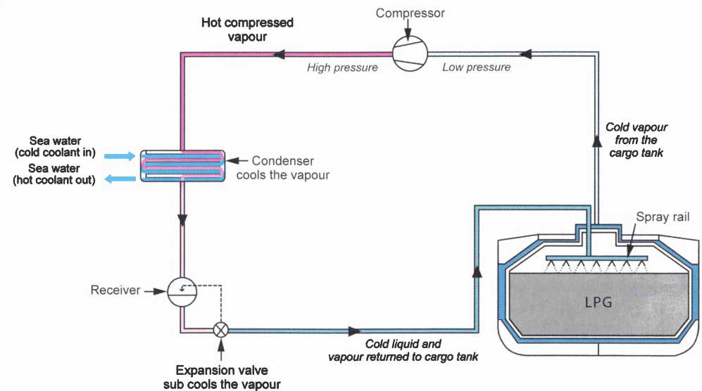
The condensed liquid is then flashed back to the tank via a float expansion valve or a level control. The liquid/vapour mixture returned to the cargo tank is normally distributed by a spray rail to maximise the cooling effect within the tank.
This cycle is also suitable where suction pressures are relatively high, as is the case in the semi-refrigerated carriage of LPG.
The Mollier diagram (Picture 27) is the European version of the Anglo-American Psychrometric chart. They are identical in content but not in appearance. Mollier diagrams show the heat quantities contained in, and the conditions of, a liquefied gas (or refrigerant) at different temperatures.
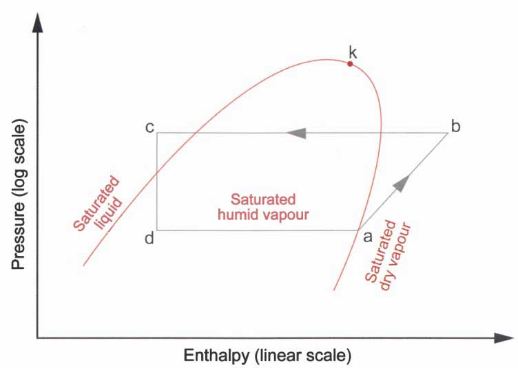
The main red line as shown depicts the saturated liquid line to the left of the apex and the saturated vapour line is shown on the right. Where they meet is called critical point “k”.
The shape shown on the diagram from point “a” is an example of the pressure and enthalpy changes that occur in a simple shipboard refrigeration plant.
- At “a” the vapour is drawn from the tanks and compressed until point “b”.
- From “b” to “c”, the vapour has heat removed from it by the condenser where it condenses to a liquid.
- Where “c” is to the left of the “saturated liquid line” it indicates that the liquid is sub-cooled. The liquid is then passed across an expansion valve and returned to the ship’s tanks.
- “cd” is always vertical and indicates the level of humidity in the returned condensate.
The total refrigeration effect of a compression cycle is the difference in enthalpy of the “vapour” drawn by the compressor at “a” and the condensate returned at “d”, measured in kJ/kg.

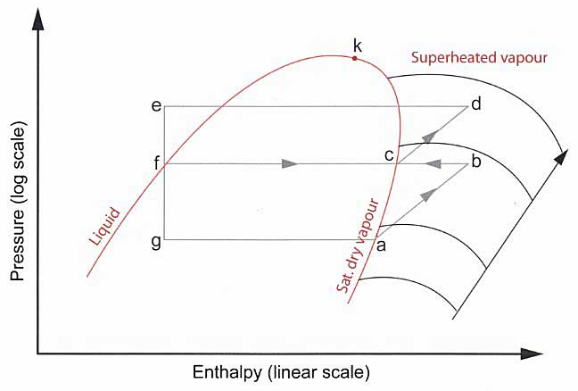
Two Stage Direct Cycle
A two stage cycle, with inter-stage cooling, is used where suction pressures are low and, as a result, compression ratios are high (assuming a seawater condenser) when compared to the single stage cycle.
Two stages of compression, with additional cooling between the stages, are sometimes necessary to limit the compressor discharge temperatures that increase significantly with each compression stage.
First stage discharge vapour is taken to an intercooler where its superheat is removed. The cooling medium is cargo liquid “flashed down” to intercooler pressure from the sea water cooled condenser/receiver. The remaining parts of the cycle are similar to the single stage cycle.
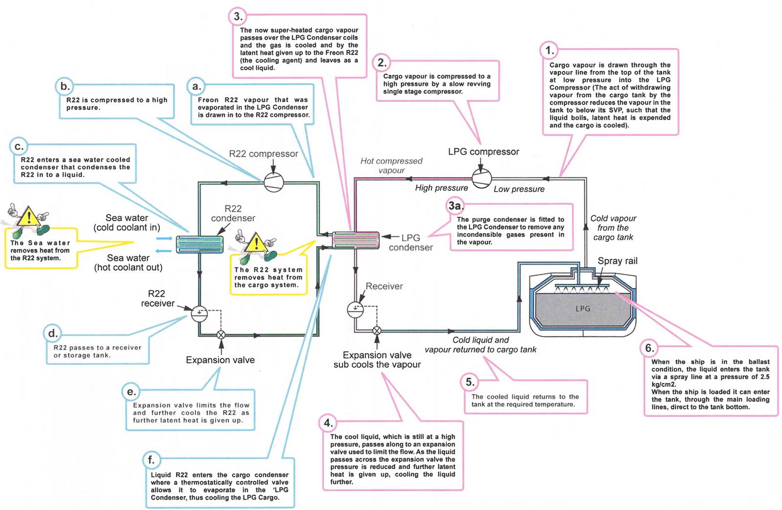
Cascade Direct Cycle
The cascade system uses a refrigerant, such as Freon R22, to condense cargo vapours.
The single stage compression of cargo vapour is identical to the single stage direct cycle, but the cargo condenser is cooled using R22 instead of sea water.
The cargo, as it condenses, evaporates the liquid R22 and the R22 vapour is then taken through a “conventional” closed refrigeration cycle, condensing against sea water hence the term “cascade”.
The cascade cycle is used for fully refrigerated LPG cargoes as plant capacity is generally unaffected by seawater temperature changes, unlike the other reliquefaction cycles.
Note: Although Freon is still used on existing vessels, Freon R22 is now prohibited on all new vessel and replaced by tetrafluroethane R-134a. (MARPOL Annex VI Reg 12 refers).
Cargo Compressors
The compressor is the main component of a ship’s reliquefaction plant. Two types of cargo compressor are used for reliquefaction purposes, reciprocating or screw. Substantially larger centrifugal compressors may be used ashore where more space is available.
1 Reciprocating Compressors
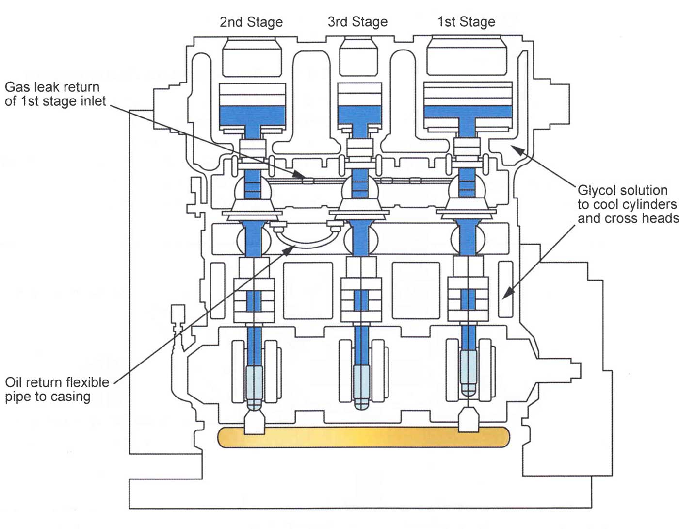
The majority of reciprocating cargo compressors used in gas carriers are oil- free compressors. In the Sulzer oil-free compressor, sealing between the piston and cylinder wall, and between the piston rod and gland, is achieved by the use of machined labyrinths.
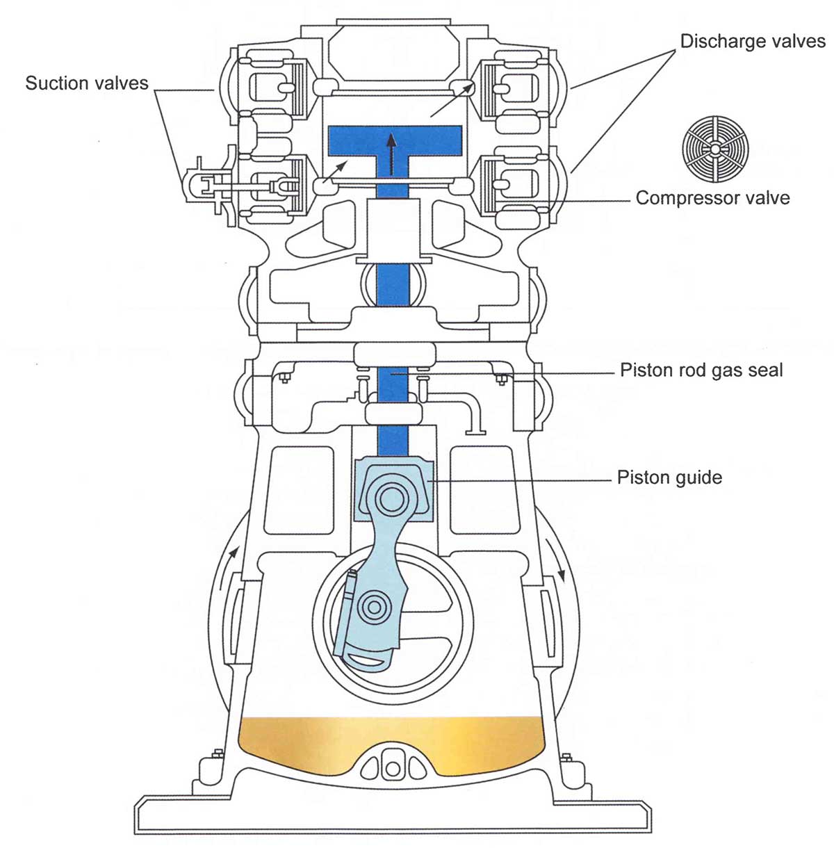
Consequently, no lubrication is needed in the cargo vapour spaces of the compressor. The absence of any contact with the seals gives minimum wear and consumption of lubricating oil.
In Linde compressors, the piston rod gas seal is constructed of poly tetra fluoro ethylene, which would be sacrificially dissolved by ammonia vapours and is therefore unsuitable for use in the carriage of that type of cargo.
When the compressor is shut-down the cargo vapour in the crankcase can condense, which would cause subsequent lubrication problems. Therefore, provision must be made for crankcase heating when the compressor is idle. When the compressor is running, cooling must be provided for the crossheads and guide bearings in the crankcase. Normally a closed cycle glycol/freshwater circulation system provides heating when the compressor is shut-down. This doubles up to provide cooling when the compressor is running.
Notes on Starting Cargo Compressors:
- Check oil level in the crankcase;
- Turn the flywheel several turns in the running direction;
- Open the suction and delivery valve;
- Check circulation of the cooling medium;
- Check that the motor is unloaded. Switch on the motor and the lube oil pressure will rise immediately to about 3,5 kg/cm2.
Notes While the Compressor is Running:
- At regular intervals (3 hrs) record the suction and discharge pressures, lube oil pressure, condenser pressure and sea water temperature;
- The compressor heads should be felt by hand during each check;
- If one of the compressor heads is hotter than the others, this normally indicates that the compressor suction or discharge valve is not operating correctly;
- If one of the compressor heads is cooler than the others, this means that droplets of LPG are entering the compressor (the heat exchanger will be found to have too much liquid);
- Generally, on long sea passages, the compressor is only run during daylight hours.
Notes on Stopping Cargo Compressors:
- Switch of the compressor, retaining full back pressure;
- According to the system set up, close the main stop valves (suction and/or discharge);
- The coolant should now circulate during stand-by periods, at a temperature of approximately 35 °C to prevent condensation of gas within the compressor and dilution of the lubricating oil;
- In all cases where the gas pressure may exceed 15 kg/cm2, when the compressor is stopped or when the gas may condense the trapped volume should be relieved.
Screw Compressors
Screw compressors for cargo use can be either dry, oil free machines or; alternatively, oil flooded machines.

In the dry machines, the screw rotors do not make physical contact but are held in mesh and driven by external gearing. Because of the leakage effects through the clearance between the rotors, high speed are necessary to maintain good efficiency (typically 12 000 rpm). In the rotor, the lobes intermesh and gas is compressed in the chambers 1, 2, 3 (see Picture 33), which are reduced in size as the rotors turn. The compressor casing carriers the suction and discharge ports.
The oil-flooded machine relies on oil injection into the rotors and this eliminates the need for timing gears, the drive being transmitted from one rotor to the other with the injected oil acting as lubricant and coolant. Because of the oil sealing between the rotors, gas leakage is much less and so oil flooded machines can run at lower speeds (3 000 rpm). An oil separator on the discharge side of the machines removes oil from the compressed gas. Capacity control of screw compressors can be achieved in a number of ways, the most common being the use of a sliding valve that effectively reduces the working length of the rotors. This is more efficient than suction throttling.
Compressor Suction Liquid Separator
With the exception of the oil injected screw compressor, it is necessary to protect all cargo compressors against the possibility of liquid being drawn in. Such a situation can seriously damage the compressors as liquid is not compressible.
It is normal practice to install a liquid separator on the compressor suction line from the cargo tanks to allow any entrained liquid to be removed from the vapour stream. This separator vessel is fitted with high level switches that alarm and trip the compressor. Liquid that is normally separated in a collecting pot is then returned back to the tank.
Purge Gas Condenser
Many reliquefaction plants are fitted with a shell and tube heat exchanger mounted above the cargo condenser. The purpose of the heat exchanger is to condense any cargo vapours that, when mixed with incondensable gases such as nitrogen, have failed to condense at the pressure and temperature present in the main condenser.
The incondensable gases, such as air or nitrogen, are displaced from the main condenser into the shell of the purge condenser as they are lighter than that of the LPG and so tend to collect at the top.
Purge condensers are fitted with an automatic venting arrangement to the mast riser to release incondensable vapours.
In the purge condenser the gases are subjected to the same pressure as is in the main condenser. However, this is at a condensing temperature that is equivalent to the outlet temperature from the expansion valve. As it is purging from the top of the purge gas condenser the condensing temperature differential allows the cargo vapours to be condensed leaving the incondensables, such as the nitrogen that does not condense until -190 °C, to be vented-off.
Starting a Reliquefaction Plant (Cascade Cycle)
- Ensure that sufficient electrical power is available.
- Seawater pumps on for Freon (R22) condensers.
- Switch LPG compressor glycol circulating pump and heating on, if it is required.
- Ensure the LPG compressor motor intermediate shaft “oil drip” is topped-up and turned on.
- Cargo tanks and lines should be setup in readiness.
- Line up vapour and condensate valves in the LPG room.
- Check R22 and LPG compressor crankcase oil levels, topping-up if required.
- Start R22 compressor and open the oil circulating valve.
- Open the R22 circulating valve on the LPG condenser.
- When the R22 cycle has settled, start the LPG compressor on 50 %.
- When the LPG cycle has settled, put the compressor to 100 % as required
- Check the R22 liquid level in the LPG condenser and, if it is high, make sure that the R22 is returning back through the R22 suction from the LPG condenser.
- Use the purge condenser when required, venting to the atmosphere as necessary.
- Watch the LPG condenser pressure and outlet temperature. These vary with the cargo carried. If the LPG condenser pressure is allowed to go too high, excess pressure will vent-off automatically, via the purge condenser; to the atmosphere.
- If a compressor failure alarm sounds, cancel and check gauges for possible cause of the failure, then rectify and restart. If the R22 compressor stops and the LPG compressor is allowed to continue running at 100 % a high LPG condenser pressure will result, with pressure being vented-off as before. If the LPG compressor stops and the R22 compressor is allowed to run for too long, sub-cooling may occur and cause congestion in the LPG condenser outlet.
- Keep a check on tank temperatures, pressures and the various oil levels on the reliquefaction machinery side.
- On completion of reliquefaction, close the plant down in reverse order to the starting procedure while ensuring as much R22 gas as possible is returned to the R22 condenser.
At check items 8, 9, and 10, if R22 liquid is already in the LPG condenser it may be advisable to start the LPG compressor first. This will evaporate the R22 liquid, enabling the R22 compressor to gain suction when started.
Methanol Injection System
A methanol injection system may be located at strategic points in the cargo and reliquefaction plant. This is used to deal with any pipes, expansion valves or pumps that may become blocked with hydrates.
Some hydrocarbon products react with water to form “hydrates”. The presence of water can be due to:
- Condensed air in the inert gas (the IG dew point is too high);
- Water content of the hydrocarbon product, particularly propane;
- Water in the cargo piping system.
Hydrates are white crystalline solids that are not soluble in water and can only be washed out by a very fine molecular alcohol known as methyl alcohol, trade name “methanol”. This solvent (i. e. methanol) is aggressive to water borne structures, dehydrating the water and leaving an acidic corrosive residue and is therefore only used with the agreement of the cargo receivers and other interested parties.
Hazards of Methanol
Methanol is a flammable, non-corrosive colourless liquid. It is toxic if swallowed and it has an accumulative poisoning effect. Its vapour is heavier than air, has a density of 1,1 and has a slightly alcoholic odour. You can be exposed to dangerous quantities of methanol before you detect its smell.
As small quantities of methanol are not poisonous it is used as an anti-freeze by direct injection at the cargo pumps and expansion valves.
Pure grades of cargo can easily be placed off-specification by the addition of methanol.
LNG Boil-off and Vapour Handling Systems
On LNG vessels the cargo boil-off vapours are not reliquefied but are instead used as fuel gas in the E/R.
Note: At the time of print there are no LNG carriers fitted with a reliquefaction plant in operation. However, in 2006 the first LNG carrier fitted with a reliquefaction plant was ordered and it added a cost of cira $ 30 million USD to the purchase price.
A reliquefaction plant would be more likely to be installed on an LNG ship if the economics of the market made it viable. However, to date they have only been fitted with the equipment to handle the boil-off vapours by collecting and heating them before they are blown, by the LD compressors, through a double walled pipeline to the boilers.
LNG vapours are lighter than au and the IGC Code permits their use in the engine room for this reason. (Note that LPG vapours are heavier than air and so are prohibited from use in the engine room).
Vessels that are designed for LNG carriage use steam turbine driven axial flow compressors to handle the vapours produced during cool down, loading and loaded passage. A Low Duty (LD) compressor usually handles the boil-off vapours produced during loaded passage, with High Duty (HD) compressors handling the vapours that are produced during loading.
The LD compressor takes boil-off vapour and uses a steam-heated vapour heater to warm it for supply to the engine room. Automatic surge controls are fitted to the compressors to protect against damage from flow reversal and subsequent surging. The surge control system ensures that minimum flow is maintained above a set value that depends on the compression ratio.
Inert Gas Systems
Inert gas is used on gas carriers to inert cargo tanks and hold spaces. Production on board generally uses one of two methods:
- Inert gas is produced by removing oxygen from the air through physical absorption;
- Inert gas is produced by combustion of gas oil. (This is the most widely used system).
Inert Gas (Nitrogen) Absorption System
Nitrogen is generated on board using a system called “pressure swing absorption”. The process is based on the use of an absorbent carbon bed, which acts as a molecular sieve, absorbing oxygen and leaving nitrogen as the unabsorbed product.
On exhaustior, the carbon beds are regenerated in a valve-operated sequential system, venting an oxygen rich waste. This type of system produces nitrogen gas of high purity, with less than 1 % oxygen. The system is normally operated in conjunction with a buffer nitrogen storage system.
High purity nitrogen gas with a very low O2 content is also termed as an “inert gas”.
Nitrogen is not commercially viable as an inert gas for purging cargo tanks, but is used in a number of areas on LNG Carriers such as:
- Inerting the hold and annular space;
- Inerting the jacket around the pipe that carries the LNG “boil-off” gas to the engine room.
Inert Gas Produced by Combustion of Gas Oil
Inert gas produced by the combustion of low sulphur gas-oil produces a low oxygen content gas that is further purified and treated to provide an inert gas of acceptable purity. The quality of the inert gas produced will vary widely, depending on the conditions under which the generator is operated.
The principles of operation of the generator are shown in Picture 36.

The system comprises of three main components:
1 Combustion chamber with scrubber and cooler
The burner is designed to ensure proper combustion with a minimum of excess air; while the combustion chamber itself is water jacketed without a brick lining. After combustion, the gas enters the washing/cooling section (i. e. the demister/R22 cooler) ala temperature of about 800 °C and is cooled and scrubbed by spraying with seawater. The gas leaves at approximately 5 °C above seawater temperature and is essentially free of the sulphur dioxide that forms during the combustion of any sulphur present in the fuel.
2 Refrigerated drier (normally cooled by a Freon gas)
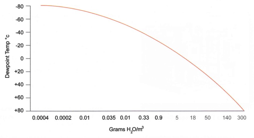
In the refrigerated drier the inert gas is cooled to approximately 4 °C, resulting in condensation of most of the water vapour present in the gas. Picture 37 shows the saturated water vapour content of inert gas as a function of temperature, the water vapour content of inert gas being much less at 4 °C than al 25 °C.
3 Absorption drier
The absorption drier consists of two vessels that are filled with activated alumina. One vessel is on drying duty while the other vessel is re-generated. The cycle time takes about 6 hours. Drying in the absorption drier reduces the atmospheric pressure dew point of the inert gas to -40 °C or below. (the relevance of a dew point of -40 °C can be seen by measuring off the water content at this level in Picture 37).
The refrigerated drier and the absorption drier are used to dry the inert gas to achieve dew points of -40 °C or less.
Combustion type generators must be located outside the cargo area and connections to the cargo system are temporary, normally via spool pieces. When the inert gas plant is not being used, temporary connections must be disconnected and blanked-off.
The main advantages of the combustion type generator as a source of inert gas are:
- The cost of the inert gas produced is much less than the purchase of pure nitrogen;
- The inert gas plant is available when necessary.
The disadvantage of this system is the quality of produced gas. Even under good operating conditions, the inert gas supplied is unsuitable for use with many of the chemical gases.
A typical output from an inert gas generator would be as follows:
| Component | % by Volume |
|---|---|
| Nitrogen | 85-86 |
| Carbon Dioxide | 14-15 |
| Carbon Monoxide | 0,1-0,3 |
| Oxygen | 0,1-0,5 |
| Hydrogen | 0,2 |
| Sulphur Dioxide | 20 ppm |
| Oxides of Nitrogen | 0-5 ppm |
| Other | Dew point -50 °C to -55 °C Ash and soot traces |
Continuous monitoring of the O2 content on the inert gas supply is required with an alarm set at a maximum of 5 % O2 by volume.
Electrical Equipment in Hazardous Areas
There is a broad classification of spaces that are either “gas safe” or “gas dangerous” on gas carriers. The gas dangerous zones on deck extend between 3 to 5 metres forward and aft of the tank section, depending on the size of ship.
Accommodation spaces are “gas safe” while compressor rooms, cargo tank areas, etc are “gas dangerous”. In gas dangerous spaces only electrical equipment of an approved standard may be used. This applies to fixed or portable electrical equipment. There are several types of certified safe electrical equipment found on gas carriers.
Intrinsically Safe Equipment
An intrinsically safe system is one in which the energy released for use in the hazardous area is limited, under normal and specified fault conditions, to well under the minimum energy that would cause the Flammability, Explosion and other Hazards of Liquefied Gasignition of a flammable mixture.
The use of intrinsically safe equipment is limited to instrumentation and control circuitry and cannot be used in power circuitry.
Note. Recent European legislation (ATEX Directives) has required the re-certification of most equipment for use in hazardous atmospheres.
Flameproof Equipment
A flameproof enclosure is one that can withstand the pressure developed during the internal ignition of an explosive mixture and whose design is such that any product of the ignition occurring within the enclosure would be cooled below ignition temperature before reaching the surrounding atmosphere. Flanged joints, through which the gases are allowed to escape, are critical and great care must be taken in assembly and maintenance to ensure that no bolts are omitted or may work loose.
Pressurised or Purged Equipment
This is a technique to ensure that an enclosure remains gas free, either by pressurisation or by purging. In the case of pressurisation, an overpressure of 0,5 mbar relative to the surrounding atmosphere must be maintained by leakage compensation while, in the case of a purged enclosure, a continuous supply of purging gas must be provided. Air or inert gas can be used.

Increased Safety Equipment
This is used for light fittings and motors. The equipment has a greater than normal separation between conductors and between terminals. Starters are designed to reduce the degree of arcing and the temperature rise. Increased safety motors are frequently used on deck on gas carriers to drive deep well pumps, booster pumps, etc. In these cases, they must be also be protected by a flame proof enclosure.
Instrumentation
Instrumentation is an important part of the gas tanker equipment. Different types of instrument are found for the primary measurement of level, pressure and temperature.
A review of these follows:
1 Liquid Level
The IGC Code states that every cargo tank must be fitted with a liquid level gauge. The Code allows for different types of gauging system, with specific requirements for certain cargoes.
The IMO classification of gauging systems is as follows:
- Indirect systems – weighing or pipe flow meters.
- Closed devices that do not penetrate the cargo tank – ultrasonic devices or radio-isotope sources.
- Closed devices that penetrate the cargo tank – float gauges, bubble tank indicators etc.
- Restricted devices that penetrate the tank but release small volumes of liquid or vapour when in use (e. g. slip tubes). When not in use, the restricted device should form a closed system.
The most common type of level gauging on most conventional /NH3 vessels are of types b) and c).
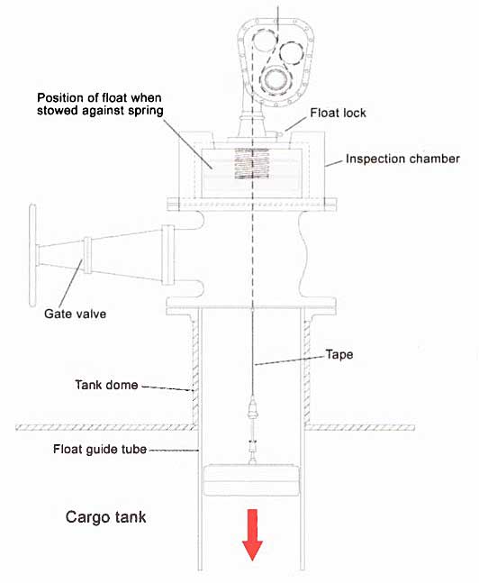
2 Float Gauges
The float gauge, which is widely used in tankers, consists of a float attached by a tape to an indicating device that can be set up for local or remote readout. When not in use the float must be lifted from the liquid and secured. If it is left down the fluctuation in liquid levels may damage the tape tensioning device.
3 Nitrogen Bubbler Gauge
This gauge measures the pressure necessary to displace liquid from a small bore tube that is mounted in the tank. Nitrogen is introduced into the tube to displace the liquid, and the pressure to do this is measured as a function of the liquid level and the liquid density. For cargoes of known density, a level readout can be directly obtained.
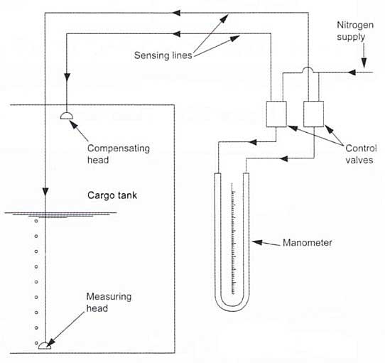
4 Differential Pressure Gauge
This device measures the differential pressure between a liquid and vapour and so the cargo density must be known. The signal lines for the instrument are normally purged with inert gas.

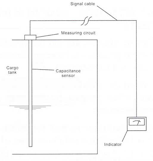
5 Capacitance Gauge
This type of device measures the variation of electrical capacitance between two probes as the liquid level changes.
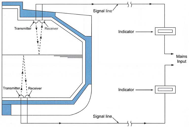
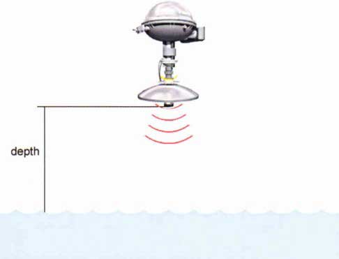
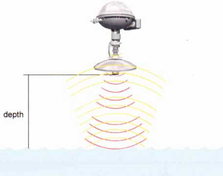
6 Ultrasonic Gauge
An ultrasonic level gauge operates in a similar manner to an echo sounder, where the time taken for a sound wave to be reflected back through the liquid is measured and then used to calculate the liquid level.
7 Tank Radar Gauge
Radar-type liquid-level gauges have been specifically developed for use on tankers.
The tank radar system is based on the same principle as the ship radar. If the speed of the radar waves is known, the time needed by the signal to reach the cargo liquid level, bounce back and be picked up by the antenna can be accurately measured.
The distance to the cargo liquid level (ullage) is:
(divided by 2 because the signal travels both ways).
Together with the pressure sensor signal and the signals of the various temperature sensors at different levels in the tank, the tank ullage signal is sent to the CCR (Cargo Control Room). The electric circuit from the dome to the CCR is an intrinsically safe one.
Using these parameters, the cargo volume can be calculated.
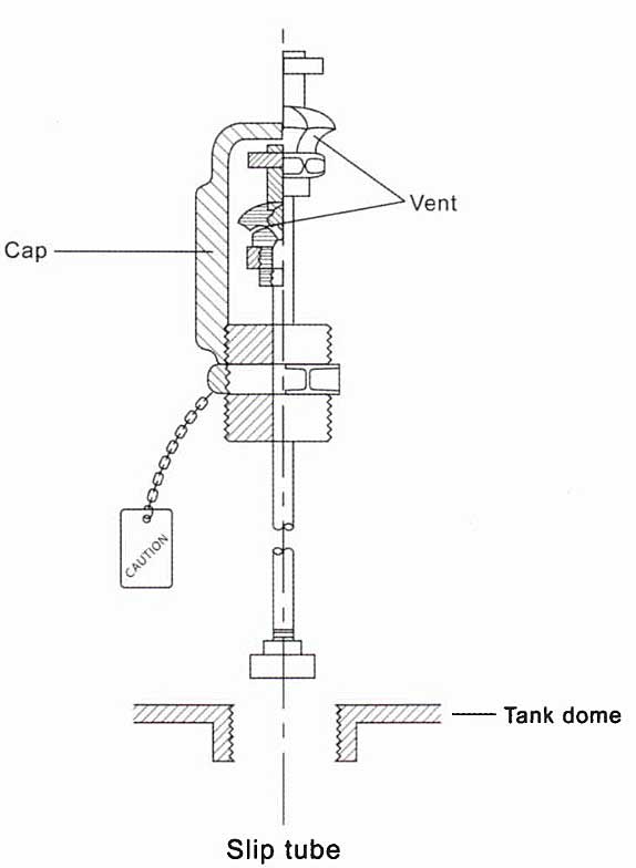
8 Slip Tubes
Use of this type of gauging device is restricted as an amount of cargo is released during measurement. The IGC requirements limit the orifice diameter through which cargo can be released to 1,5 mm unless an excess flow valve is provided. The device has a sliding capillary tube that penetrates the tank. This tube is glanced at the tank penetration point and can be raised or lowered within the tank. Liquid or vapour issuing from the orifice provides an indication of the position of the liquid/vapour interface. This is a simple and direct method of measurement but special precautions must be taken, e. g. protective clothing, the spray must be directed away from personnel and the tube must be closed when it is not in use.
9 High Level Alarms
With the exception of Type “C” tanks that have a capacity of less than 200 m3, every cargo tank must be fitted with an independent high level alarm that provides both audible and visual alarm.
There are 3 levels of alarm. As an example, for a filling ratio of 98 %:
- A high level alarm will sound at 95 % of the tank volume (audio and visual warning). This early warning alarm can be activated either by the tank level measuring system or by an independent sensor.
- A high level alarm will sound at 98,5 % of the tank volume (audio and visual warning that differ in sight but not in sound from the 95 % alarm). Isolation of the overfilled tank will automatically take place by shutting the tank loading valve. If the early warning alarm is activated by the tank level measuring system this high level alarm must be activated by an independent sensor.
- A high-high level alarm at 99 % of the tank volume (audio and visual warnings that differ in sight from the 95 % and 98,5 % alarms). The ESDS will be automatically activated. If the high level alarm is activated by the tank level measuring system the high-high level alarm must be activated by an independent sensor.
The high level and high-high level alarms must automatically stop the flow of cargo to the tank.
10 High Level Alarms
When loading cargo, there is a risk of generating a significant pressure surge if the loading valves close to quickly against the shore pumping system. To avoid this, the IGC Code stipulates that ESD valves will close in all service conditions with a maximum closure time of 30 seconds from the initial signal.
Alternatively, an ESDS can be put aboard by the terminal and the tank level/alarm shut-down system disconnected.
11 Pressure and Temperature Monitoring
The IGC Code requires pressure monitoring throughout the cargo system, including cargo tanks, pump discharge lines, liquid and vapour crossovers, etc. It also requires at least two devices that indicate cargo temperatures, one placed at the bottom of the cargo tank and the other near the top, below the highest allowable liquid level. In practice, most tanks also have a mid-sensor that provides temperatures for the top, middle and bottom.
Where cargo is carried in Type “A” tanks below -55 °C, the IGC Code requires temperature indicating devices within the insulation or on the hull structure adjacent to the Liquefied Natural Gas and Liquefied Petroleum Gas Cargo Containment Systemcargo containment systems. The devices should be set to alarm at the lowest temperature acceptable to the hull steel to prevent cold spot damage.
12 Vapour Detection Systems
The IGC Code requires gas carriers to have a fixed gas detection system with audible and visual alarms installed throughout the vessel, though the use of portable gas detectors may be permitted when carrying toxic gas cargoes.
Detector heads must be provided in the following areas:
- Cargo compressor room;
- Electric motor rooms;
- Cargo control rooms, unless they are classified as gas safe;
- Enclosed spaces, such as hold spaces and inter-barrier spaces;
- Air-locks.
The detector heads should be sited by taking into account the range of cargoes likely to be carried, i. e. heavier than air vapours at a low level and lighter than air vapours at a high level.
The alarms from the gas detection system will normally be monitored from either the cargo control room or the navigational bridge. Provision should be made for regular testing of the installation and span/calibration gas should be readily available, permanently piped if possible.
Sampling and analysis of each detector head is done sequentially and sampling intervals must not exceed 30 minutes. Alarms should be activated when the vapour concentration reaches 30 % LFL of the particular flammable vapour being sensed. Toxic gas measurement is carried out at 4 hourly intervals at sampling heads located in each hold or interbarrier space.
In addition to the fixed gas detection system every gas carrier must have at least two sets of portable gas detection equipment suitable for the products being carried. A suitable instrument for oxygen measurement in inert atmospheres must also be carried.
All personnel on gas carriers should be familiar with the gas detection equipment provided and its limitations. Manufacturer’s instructions must always be fully read and understood.
13 Custody Transfer System
Most LNG vessels are fitted with a “custody transfer system”. This is an integrated system of cargo instrumentation that allows cargoes to be bought and sold by heat value in BTU (British Thermal Units) or Kilo/cal. To determine the amount of energy transferred, accurate volume, density and composition measurements must be made by the system and the information returned to a data logger and computer for recording and calculation.