This article looks at the categories, designs and standards of liquefied gas carriers and their containment systems (tank types).
It explains the different options for refrigeration or pressure and provides an understanding of the reasons for each design decision. Real examples of the ship types are provided.
Principles of Gas Carrier Design and Construction
The basic requirements for the design and construction of gas carriers are extremely rigorous and are specified in the IMO “Codes for the Construction and Equipment of Ships Carrying Liquefied Gases in Bulk”, of which the lnternational Gas Carrier Code, or IGC Code, is the most up-to-date reference and should be used in conjunction with SOLAS.
Gas carriers built before 1986 complied with the IMO Gas Carrier (GC) Code and before 1976 with the Existing Gas Carrier Code (EGC).
A ship that complies with the IMO Code can be issued with an “International Certificate of Fitness for the Carriage of Liquefied Gases in Bulk”, which confirms a minimum standard of constructional safety. If a vessel is to comply with the code throughout its lifetime it must be periodically re-inspected.
Many factors are taken into consideration, all of which can affect the eventual design. These include the types of cargo to be carried:
- conditions of carriage (e. g. fully-pressurised, semi-pressurised, refrigerated and fully refrigerated);
- type of trade, which in turn determines the degree of flexibility required of the ship;
- terminal facilities that will be available when loading or discharging the vessel.
There are many different designs of gas carrier and containment systems. This article contains descriptions of those most commonly encountered.
Cargo Containment System
The IGC Code identifies four different types of cargo containment system. They are:
- Independent tank types (Type “A”, “B” or “C” tanks);
- Membrane tank types (Technigaz/Gaz Transport);
- Semi-membrane tanks (a variation of the membrane tank system);
- Integral tanks (built as part of the hull, like a conventional tanker).
Independent Tank Types
Independent tanks are completely self-supporting and do not form part of the ship’s hull. The design pressure will determine which of the 3 allowable independent The Liquefied Gas Tanker typestank types are used.
1 Type “A” Tank
General Overview
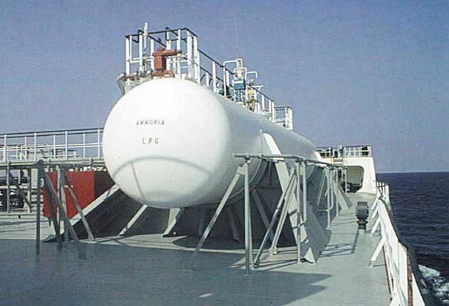
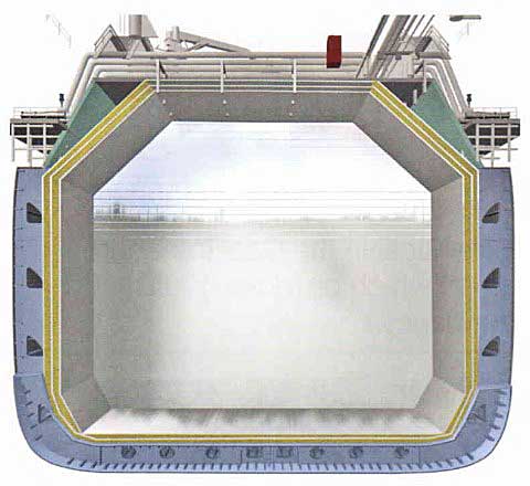
Type A tanks are constructed from low temperature steel (Arctic D) of a prismatic shape, making use of the maximum amount of space within the hull. The maximum allowable vapour pressure in this type of system is normally 0,25 kg/cm2. This means that cargoes must be carried in a fully refrigerated condition and at or near atmospheric pressure. Picture 1 shows a cross-section of this type, the example being a fully-refrigerated LPG carrier.

Construction
A type “A” tank is constructed as a self-supporting prismatic tank that requires considerable internal stiffening. The stresses in these tanks are not determined as accurately as, for example, a pressure vessel type tank. Therefore, to protect the ship’s hull from low temperatures and to ensure safety in the event of cargo tank leakage, a secondary containment system is needed. This secondary containment system is known as a “secondary barrier” and is a feature of all ships with Type “A” tanks that are capable of carrying cargoes at temperatures of below -10 °C.
Where liquefied gas is carried in a tank that is not a pressure vessel, a second barrier may be necessary.
For a typical fully-refrigerated LPG carrier (which will not carry cargoes below -55 °C) this “secondary barrier” must be a complete barrier that is capable of containing the whole tank volume. It may form part of the ship’s hull, which is an approach generally adopted, so the hull will be of a special steel that is capable of withstanding low temperatures.

The alternative is to build a separate secondary barrier around each cargo tank. Any secondary barrier must be able to contain tank leakage for a period of 15 days. The space between the primary tank (sometimes referred to as the “primary barrier”) and the secondary barrier on LPG Carriers is known as the hold space or void space. When flammable cargoes are carried, these spaces are filled with inert gas that, in the event of primary tank leakage, prevents a flammable atmosphere from being created.
When non-flammable cargoes are carried the hold spaces can be filled with air. Thermal insulation can be applied either to the outside of the primary tank or to the inner hull.
Insulation
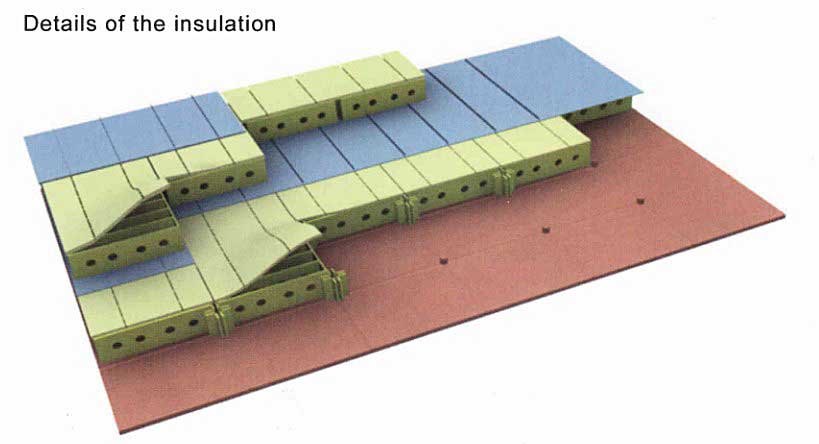
The cargo tanks are externally insulated by 120 mm thick polyurethane foam panels, covered by a 0,5 mm flat aluminium sheet and each fastened to the tank hull by polyethylene studs.
An insulation system is designed to keep the vessel and adjacent tank spaces under normal operating conditions while maintaining the cargo fully refrigerated as a liquid.
There is a space of approximately 10 mm between each of the polyurethane panels and this is filled up with foam strip and covered with self-adhesive tape (Teroson). This makes the insulation cover vapour-tight and relatively water-tight and prevents the ingress of humidity from the surrounding atmosphere of the hold spaces.
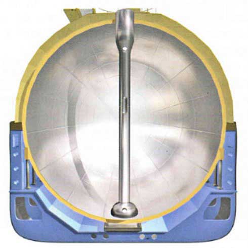
2 Type “B” Tank
General Overview
Type “B” tanks are generally spheres, although the Code makes provision for constructing them from plane surfaces. The maximum allowable vapour pressure in this type of system may be slightly higher than in a type “A” tank, e. g. 0,35 kg/cm2.
Construction
This type of containment system is subjected to a thorough stress analysis, including fatigue life and crack propagation analysis. Because of its design, the Type “B” tank requires only a partial secondary barrier that comprises a drip tray and a splash barrier.
In this design the hold space will be filled with either inert gas or air when it carries flammable cargoes. When dry air is used, the hold must be capable of being made inert if any cargo vapour is detected.
Read also: Cargo Containment Systems of LPG and LNG
Above deck, a protective steel cover is applied to the tank (weather cover) and insulation is applied to the outside of the tank.
A protective steel dome covers the primary barrier above deck level and insulation is applied to the outside of the primary barrier surface. The spherical Type “B” tank was originally designed for LNG carriage, but is frequently used for ethylene carriage.
Insulation
The cargo tank is a thick, self-supporting, aluminium sphere that is carried by a cylindrical skirt at its equator. The containment system is based on the principle of “leak before fail”.
The insulation system consists of two layers:
- Layer 1 = phenolic resin foam.
- Layer 2 = polyurethane foam.
The insulating structure is reinforced by wire nets and covered with AL-PET aluminium foil sheet. The insulation also doubles as a “Spray Shield”.
Any leaked cargo drains by gravity, through the annular space between the cargo tank and the insulation, to the bottom sphere. An opening in the insulation leads to a “rupture disc”, which bursts under cryogenic temperatures, allowing the liquid to drain into the drip-pan in the cargo hold space beneath.
3 Type “C” Tanks
General Overview
Type “C” tanks are usually horizontal cylindrical pressure vessels that are designed for pressures higher than 0,7 kg/cm2.
Construction
This type of containment system is used in semi and fully-pressurised gas carriers and is the construction used for deck tanks on all LPG carriers.
Type “C” tanks are designed and built to conventional pressure vessel codes and, as a result, are subject to accurate stress analysis. Where this type of system is used, no secondary barrier is required and the hold space (when located within the vessel’s hull) can be filled with either inert gas or air.
In the case of a typical fully-pressurised ship (ambient temperature carriage), the vessel may be designed for 17 kg/cm2. By comparison, a typical semi-refrigerated ship would be designed for approximately 7 kg/cm2 gauge pressure and a 50 % vacuum (-0,5 kg/cm2 gauge pressure) with tank steel capable of withstanding -48 °C.
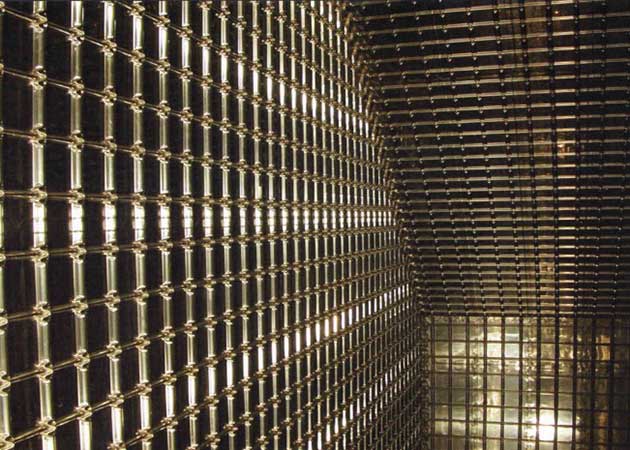
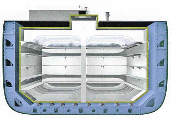
Membrane Tank Types
General
The membrane cargo containment system is based on a very thin primary barrier or “membrane”, supported by a layer of insulation within the confines of the hull of the ship.
A secondary barrier is a back-up protection, outside of the primary tank, which can contain the cargo for a period of fifteen days in the event of an emergency.
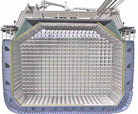
The membrane system differs from the self- supporting tanks as the containment system must be provided with a complete secondary barrier to ensure cargo integrity in the event of leakage of the primary barrier. There are two principal types of membrane system in common use, both of which are named after the companies that developed them, Gaz Transport and Technigaz (the companies have now merged to create Gaz Transport Technigaz GTT).
Until recently the maximum size of LNG Carrier was about 135 000 m3, and the ship-owner would choose either a membrane or type “B” sphere construction. However, the recent move toward much larger LNG Carriers (up to 250 000 m3 in 2006) has created a dominance by the membrane design as it makes better use of the inner hull space.
1 Gaz Transport Membrane System
The Gaz Transport membrane system is fitted to most of the existing membrane type ships. The primary and secondary layers are identical in the Gaz Transport system, which provides 100 % redundancy.
Invar is a stainless steel alloy of about 36 % nickel and iron with almost no shrinkage factor.
The primary and secondary layers are constructed of a 0,7 mm thick invar skin and a 200 mm layer of perlite-filled plywood boxes that act as insulation.
The thickness of the insulation layers is adjusted at the design stage to achieve the desired cargo boil-off rates for fuelling the ship’s boilers, a practice in most trade routes though future LNG Carriers may be fitted with reliquefaction plants. Nippon Yusen Kaisha (NYK) operates the first LNG Carrier; the “LNG Jamal”, equipped with a reliquefaction plant.
Invar is chosen for the membrane as it has a negligible coefficient of thermal expansion. “Invar” is short for “invariable”.
2 Technigaz Membrane System
In the Technigaz system the primary barrier is stainless steel that is constructed of “cross corrugations”, that “waffles”, to allow for expansion or contraction.
The primary barrier is supported by an insulation layer made of reinforced cellular foam. In between the insulation layers is a cloth of laminated fibreglass and aluminium that acts as the secondary barrier This secondary barrier is able to contain cargo leakage for 15 days.
3 Gaz Transport Technigaz Containment System 1 “CS1”
The cargo containment system known as “CS1” is a recently developed hybrid that combines the advantages of the existing Gaz Transport Technigaz systems (i. e. No 96 and Mk III).
It uses a primary invar membrane supported by the existing Mk III type insulation panels, including a secondary “triplex” membrane.
Requirements for a secondary barrier are raised if the cargo temperature is below -10 °C. Note: For cargoes down to -55 °C the ship’s hull may be used as 2nd barrier provided it is of a suitable material. However, if the cargo temperature is colder than -55 °C, the ship’s hull is not on acceptable secondary barrier.
The first vessel of 74 000 m3 fitted with CS1 had her delivery date delayed until late 2006 because of problems with the adhesive in the secondary membrane.
Cost savings are estimated at 15 % for the CS1 system, because a higher level of prefabrication is possible.
4 Self-Supporting Prismatic Type (SPB, IHI)
At the time of publication (2007) this containment system had only been fitted on two LNG Carriers.
The tank is made from aluminium and, because of the tank’s enhanced design, it requires only a partial secondary barrier. The advantage of the self-supporting prismatic type of tank is that, with the entire tank situated beneath the vessel’s deck plating, it maximises the use of space within the ship’s hull.
For this reason the design may become more popular in the future. Provided that the hold space can be quickly made inert if cargo vapour is detected, it is acceptable for it to be filled with dry air.
Materials of Construction
The cargo tank materials used are dictated by minimum service temperatures and cargo compatibility.
Because most metals and alloys become brittle below a certain temperature, the most important property considered when selecting cargo tank material is toughness at low temperatures.
Fine grain treatment of structural carbon steels can be used to achieve low temperature impact characteristics and the IMO Code specifies low temperature limits of down to -25 °C for varying grades of such steel. (Reference should be made to the IMO Code for specific details).
Typically, ships carrying fully-refrigerated LPG cargoes will have tanks capable of withstanding -55 °C. To achieve this, service temperature alloy steels such as fully milled fine-grain carbon manganese steel must be used, sometimes alloyed with 0,5 % nickel.
A ship specifically designed to carry fully- refrigerated ethylene (atmospheric pressure boiling point – 104 °C) or LNG (atmospheric boiling point -163 °C), must use nickel alloyed steels, stainless steels or aluminium.
Insulation
Thermal insulation must be fitted to cargo tanks for the following reasons:
- To minimise heat flow into the cargo tanks and so reduce boil-off.
- To protect the general ship structure from the effects of low temperature, particularly around the cargo tanks.
- To minimise the size of reliquefaction plant required.
The main characteristics required of any insulation material are as follows:
- It should have low thermal conductivity.
- It should be non-flammable or self-extinguishing.
- It must be able to bear a load.
- It should have the ability to withstand mechanical damage.
- It should be lightweight.
- It should be unaffected by the cargo liquid or vapour.
Vapour sealing to prevent the ingress of water and water vapour into the insulating material is very important. Not only can the ingress of moisture result in loss of insulation efficiency but, in the worst case of condensation and freezing, extensive damage can occur.
To help to avoid this, humidity conditions in hold spaces must be kept as low as possible.
The following are the main materials used for insulation in gas carrier construction, together with their characteristics and approximate value of thermal conductivity at 10 °C:
| Zone 0 | Intristically safe Special protection | Ex. ia. Ex.s (certified for use in zone 0) |
| Polyurethane | Pre-formed, sprayed or foamed Thermal conductivity 0,02-0,03 J/(ms °C) | |
| Mineral Wool | Slab or roll form Thermal conductivity 0,03 J/(ms °C) | |
| Balsa | Load bearing insulant used in LNG containment system designs. Thermal conductivity 0,05 J/(ms °C) | |
| Perlite | Thermal conductivity 0,04 J/(ms °C) | |
| Polystyrene | Thermal conductivity 0,036 J/(ms °C) | |
Thermal insulation may be applied to various surfaces, depending on the design of the containment system. For Type “B” and “C” containment systems, insulation is applied directly to the cargo tank surfaces. For Type “A” cargo tanks, insulation can be applied either directly to the cargo tank or to the inner hull. Insulation applied directly to the cargo tank is the more common solution.
Hold Spaces
The hold space, also known as the void or interbarrier space, is the space located between the tanks and the ship’s hull.
On LPG Carriers it is kept under a dry inert gas. It may be kept under constant dry air when carrying ammonia cargoes.
On LNG Carriers, the hold space is normally filled with dry air, provided the space can be made inert if cargo vapour is detected. The inert gas used is nitrogen.
Bustring Disc
If a catastrophic fallure of the cargo containment system caused a leak of cargo into the hold spaces, a large amount of vapour would be generated by the rapid boiling of the cargo. This would be allowed to escape into the atmosphere via a large deck pipe opening. The entry to this pipe is a stainless steel type bursting disc. In most cases the disc does not actually burst but instead the bi-metallic plate contracts and bends back (opens) in the presence of cryogenic liquid.