The Liquefied Natural Gas (LNG) marketplace is inherently complex and is becoming quite competi-tive. Automation strategies have become a key element for aligning business needs with operating practices to increase competitiveness. There are various components of a best in class automation system. From the field sensors to boardroom information, choices for the controls and automation impact the effectiveness and profitability of an LNG operation. A well-designed, maintained, and leveraged control system will reduce start-up time, maintain maximum operating profit, avoid forced shutdowns, keep operating and maintenance costs as low as possible, assist in the management of environmental compliance, and support plant safety and security needs without adversely affecting construction costs. Though automation represents only 2 to 6 % of the typical project spending, its impact on the operations over the plant life could be around 15 to 30 %. The main objectives of the LNG plant automation are the safe, reliable operation and optimization of both the process operations and the plant asset utilization.
- Introduction
- Objectives of LNG plant automation
- LNG plant process control/automation development and functionalities
- Distributed control system
- Intelligent field devices
- Data historian and alarm management
- Safety instrumented system
- Inventory management
- Asset management system
- Process control of key units in LNG plants
- Inlet facilities
- NGL recovery unit
- Fuel gas system
- Liquefaction system
- Storage and loading
- Advanced process control and optimization of LNG plants
- Model predictive control technology
- Advanced process control implementation steps
- Benefits and challenges in applying advanced process control in LNG plants
- dvanced process control for individual units in LNG plants
- Process control and automation in LNG import terminals
- Basic process control systems
- Terminal information management system
- Optimization in LNG receiving terminal operations
- Case study 1: advanced process control for APCI C3MR LNG process
- Estimation of benefits from APC implementation
- Design and implementation of LNG advanced process control
Introduction
The history of plant automation is one of rapid technological progress. Early days of automation were characterized by manual operation of the valves by operators in the field. This was followed by pneumatic control systems, whereby the signals were transmitted pneumatically via air pressure and calculations were performed by mechanical computation devices. This enabled the use of automatic control using algorithms like proportional, integral, and derivative (PID) control. The sensor technology also started to improve accordingly. The pneumatic control systems were gradually replaced by electronic systems.
The introduction of distributed control system (DCS) in the 1970s enabled several new innovations in the plant automation field. The control became centralized with operator displays, alarm panels, and field stations. Another important development was the rise of microcomputers, which resulted in the widespread acceptance of computer-based control. This also facilitated the development of several control algorithms and plant optimization technologies that have since matured. The future of auto-mation in the LNG plant is geared toward intelligent field devices and further innovations in asset management and asset optimization. The concept of Collaborative Process Automation, which involves delivering information at the right time to the right people, is also expected to become widespread. Advanced process control (APC) and other optimization techniques are expected to become more standard tools in LNG plant operations.
The key aspects related to the automation and controls of LNG plant and import terminals are described in this chapter.
The chapter gives an overview of main automation functionalities in the LNG plant and their applications. The control of individual units in the LNG plant is discussed, where the main control loops in each unit are described. The chapter includes a discussion on APC, which is being deployed widely in LNG plants. A brief overview of the control and automation of LNG import terminals is also included.
Objectives of LNG plant automation
The key objectives of LNG plant automation are the following:
- Safety. Safety is the first and foremost objective in the LNG plant automation. Design and functionalities of key areas of the automation systems are directly are related to this. The first step in achieving this goal is to maintain the important process variables in the safe operating limit. This is accomplished by the base and advanced regulatory loops in the plant. The alarms and trips in the DCS are designed to warn the operators or take action about any impending violation of the safe operating limit. The SIS system is designed to ensure that the plant is safely shut down in case any significant violation is detected;
- Stable operation. The smooth and stable operation of the LNG plant is another important objective of the automation system. This is achieved by the base regulatory controls in the plant. Hence, the design and tuning of these control loops are critical for the stable operation. Apart from these, advanced regulatory controls and advanced process controls can be utilized to enhance the operational performance of the plant;
- Operations optimization. The optimal operation of the LNG plant that considers the various market factors and operating conditions is economically beneficial. This is best achieved by using APC/Real Time Optimization;
- Asset performance optimization. The proper management of plant assets is important in the overall optimization of plant life cycle. This includes both asset management and maintenance management.
LNG plant process control/automation development and functionalities
The selection of the process control and automation platform is a strategically important decision that impacts the long-term performance of the facility. The process control and automation system development for LNG plants during construction normally is done by the EPC contractor. In some cases, a Main Automation Contractor (MAC) is identified, who acts as a single point responsible party for all automation related aspects of the project. This is one approach for achieving sustained benefits across all three (construction, startup, and operational) phases of LNG asset life.
Distributed control system
Distributed control systems (DCSs) were introduced in the early 1980s to avoid the proprietary PLC and other systems. Initially, the control was performed at the local level. With the appearance of microcomputers, distributed control became possible in the plants.
The backbone of a DCS is a data highway, used to communicate between various elements. There could be several data highways depending on the scope. It also acts as the main data link between the main control computer and other parts of the network. In the common DCS architecture, micro-computers attached to the process are used to perform lower level calculations like unit conversion. The results from this are then passed on to higher level computers that are responsible for more complex calculations like control algorithms.
The following are the main elements of the typical DCS system (Figure 1):
- Local control unit. These units are capable of handling a number of individual PID units;
- Data acquisition unit. Both discrete and analog I/O can be handled with these units;
- Batch sequencing unit;
- Local display;
- Bulk memory unit. The various historical data are archived and stored in these units;
- General purpose computer. These are used to perform more complex calculations like optimization, advanced control, etc;
- Central operator display. This typically consists of consoles for operator communication with the system;
- Data highway. This is the main digital data transmission link connecting the various components of the system;
- Local area network.
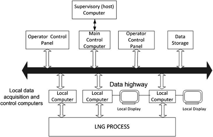
The key role of the DCS system in the day-to-day plant operation is to maintain the various process variables for smooth and stable operation. This is accomplished using the base and advanced regu-latory control schemes in the DCS.
Base regulatory control
The base regulatory control layer is the main control layer in the plant, which ensures that the operating variables are maintained at desired values. These are normally PID control loops that control the pressure, temperature, flows, etc., in the plant. These loops are executed with a frequency of one second or less to ensure fast response. The proper design of this control layer is the key to stable and optimal operation of the facility.
PID control
The PID control is the main control technology used in the plant. The PID control algorithm is a singleloop control algorithm that utilizes proportional, integral, and derivative action to maintain the variable at a setpoint. One or more of these actions can be selectively utilized, depending on the variables that are being controlled.
There are various PID equations that are available in commercial DCS systems, which are im-provements over the base PID equation. The main control tuning parameters for the PID control are the proportional gain, integral time, and the derivative time. These are selected to achieve desired closed loop performance like minimum overshoot, fast settling, and so on. Various tuning methodologies developed over the years are available for PID controllers.
An overview of the various PID loops that are used in the LNG plant is given later, where process control of the individual units is discussed.
Advanced regulatory control
Advanced regulatory control involves control strategies beyond the normal PID control. These are still configured in the DCS system. These control schemes are used for certain control loops that are challenging and not handled by the regular PID algorithm alone.
Types of advanced regulatory controls
Different types of advanced regulatory control loops are available to improve control performance. Some of the common loops are described here.
- Cascade control. In cascade control, the master controller sends its output to the slave controller, which uses it for its setpoint. An example is the level control scheme, where the level controller (master) sets the setpoint for the flow controller (slave);
- Ratio control. Ratio control is used to maintain the flow rate of one process stream at a specified proportion to that of another. An example is the specification of reflux rate as a fixed ratio to the column feed rate;
- Override control. Override control schemes are used to decide between competing control objectives. This is used to take control of output from one loop to allow another, more important loop to manipulate the output. Override control is mostly used to maintain one or more limits with a single control handle;
- Feed-forward control. This is used to handle disturbances that affect the process in an adverse manner, but may not be compensated by the control handles in a timely manner.
In feed-forward control, a model that predicts the effect of a disturbance on the controlled variable is utilized to determine the appropriate control actions in advance to offset the effect of the disturbance. Ratio control can be considered as a very basic feed-forward loop.
Other advanced regulatory control schemes are available in the commercial DCS systems. With proper implementation and tuning, advanced regulatory control schemes can improve the overall controllability of the LNG plant significantly.
Loop management
Loop management functionality offers comprehensive online control loop and valve diagnostics and reporting, expert loop tuning, and continuous Crew Evaluation Test online about Remote Control System AutoChief4remote monitoring to help ensure maximum control loop performance over time. A brief description of the capabilities that are usually present in the loop management system scope is given here.
- Controller monitoring. Here, the performances of the various PID loops in the plant are monitored on a continuous basis. Typically, it is found that some of the control loops are run in manual, which is not desirable. This issue can be addressed using diagnosis of the controller performance problem using statistical techniques. The problem could be controller tuning, sticky valves, actuator problems, and the like. Once the problem is diagnosed, an appropriate solution can be implemented. All the loops can be monitored using key performance indicator (KPI) values developed for the best performance enhancement;
- Controller tuning. Different tools to perform optimal controller tuning are available in the plant DCS. These tools can be used to identify the tuning parameters for the various PID controllers in open-loop or closed-loop mode. Various tuning criteria can be used to optimize the tuning of controllers for either setpoint tracking or disturbance rejection;
- Remote monitoring. Remote monitoring is a valuable tool to identify and troubleshoot any field problems remotely. With the advent of Ethernet-based and Internet-enabled systems, it is possible to perform remote monitoring at any location with a smartphone or other device;
- Valve diagnostics. DCS systems with the latest technology provide enhanced functionality to utilize field device data for enhanced monitoring and diagnosis. One of the valuable applications of this is the valve diagnostics. This includes identifying any sticky valves, valves with excessive wear or other issues, and subsequent troubleshooting of the problem. This can significantly contribute toward enhancing the overall plant control performance.
Intelligent field devices
An automation strategy begins with the selection of field devices such as transmitters, valves, and rotating equipment monitors. Intelligent field devices can lead to reduced capital costs while allowing a digital automation network to receive the maximum amount of information on which to act. Digital systems run throughout a facility carrying important process and equipment information from the devices to enable process control, asset optimization, and safety functionality. These digital plant networks create a wealth of data enabling unprecedented information about overall plant performance.
The increased use of intelligent field devices has resulted in safer, more reliable, and more productive processes with the added benefits of lower costs and faster implementation. Intelligent field devices with digital capabilities that include predictive diagnostics for monitoring equipment and process health as well as open-standard communications offer the LNG process system designer many benefits. These include precise measurement and control to reduce process variability and the ability to use multivariable field devices to reduce the number of products required. The higher level of information that is available enables more informed decision-making from the control room to the executive suite.
Open communications standards including Fieldbus and other digital protocols enable timely transmission of data generated by field devices. Built-in diagnostics provide the capability to monitor asset health and predict problems before they develop into faults that could interrupt production or result in a safety or security situation. Asset management software can deliver these predictive diagnostics from the most critical production assets in the facility, including control valves, transmitters, and motor-pumps.
Fieldbus protocols are an all-digital, two-way communications technology for plant instrumen-tation. Automation architectures based on Fieldbus improve operations by providing access to data not previously available while reducing maintenance costs through expanded access to diagnostics and other digital device information. Engineering drawings are simplified by Fieldbus technology, and wiring and connection costs are decreased. Fieldbus technology also permits control in field devices, providing greater engineering flexibility and reliability options in contrast with traditional control systems. Fieldbus protocols were developed specifically to meet the needs of the process industry. They have become worldwide standards accessible to multiple suppliers and open to innovation.
The diagnostic capabilities of digital intelligent field devices enable users to manage the health of the devices themselves as well as the process to which they are connected. Fieldbus devices report a good, bad, or uncertain status, and asset management software enables individual devices to be interrogated to determine their status. Screen graphics allow operations and maintenance personnel to “look inside” these assets from a centralized control room, making it easier to pinpoint the location and nature of a problem and dramatically reduce the troubleshooting effort required.
Online, real-time diagnostics running in intelligent field devices provide the information needed to streamline maintenance activities. The diagnostics run continuously in the devices and generate alerts that enable operations and maintenance personnel to identify issues and take actions that prevent abnormal situations. This enables the scarce maintenance resources, typical of most production en-vironments, to focus on assets that require immediate attention.
By using diagnostic and asset management software to identify deteriorating equipment or process conditions and potential problems, maintenance engineers at an LNG plant can predict how long it will be before equipment will fail or a potential safety or security issue will develop. Remedial action can be scheduled on the basis of actual conditions rather than a predetermined schedule, thereby safely maintaining production at optimal levels. By resolving problems before they interfere with production, the unscheduled breakdowns and work stoppages that are typical of a reactive maintenance regime can be avoided.
Leading automation suppliers offer a complete range of intelligent devices and process automation solutions that extend the digital architecture across the complete LNG supply chain, including control valves and regulators, transmitters and analyzers, motor-pumps, metering skids, gauging, and ultra-sonics. Typical integrated solutions include best-in-class turbine/compressor antisurge protection, LNG storage tank management, terminal management and custody transfer, gas processing and transmission, safety instrumented systems, and marine and offshore applications.
Fieldbus in LNG plants
A fieldbus is an industrial network communication system for real-time distributed control. It connects field instruments and measurement with control devices via serial, two-way communication systems. It is increasingly used in the area of process automation. Fieldbus encourages the move away from switches to transmitters, thus enhancing performance and flexibility (Figure 2). The potential paybacks include reduced life cycle costs and improved access to information.
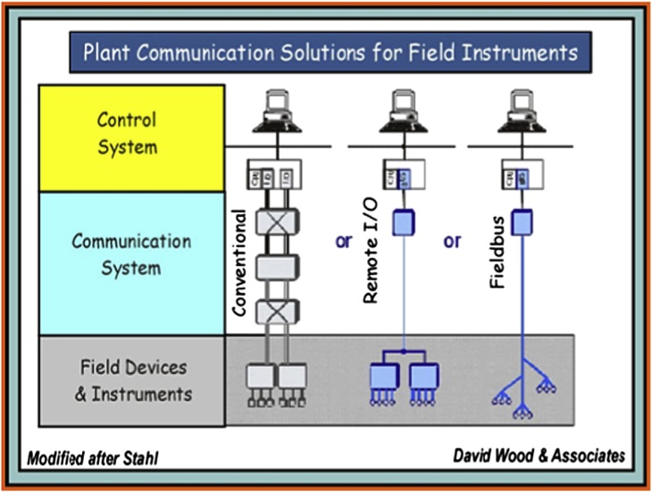
Fieldbus is also an enabling technology for knowledge-based decision-making to improve plant operations. It enables real time diagnostics and preincident information. The information and knowledge gained can be used to enable real-time information management applications and pre-dictive maintenance functions that improve the overall plant performance.
A prominent fieldbus technology that is widely used is Foundation fieldbus. It is an all-digital, serial, two-way communication system that serves as the base level network in a plant. It is the local area network for the instruments used in process automation with built-in capacity to distribute control applications across the network. LNG plants can employ Foundation fieldbus to interconnect the field equipment, such as transmitters, sensors, and valves, on a single network. In this technology, true distributed control is achieved by enabling control capability at the device level across the plant.
LNG plants usually are located in remote environments, which make fieldbus an attractive tech-nology to consider. The capability for remote diagnostics, predictive maintenance, Internet/web-based connectivity, and remote reporting has the potential to minimize downtime and drive down the life cycle project costs substantially.
Data historian and alarm management
Plant historians allow real-time event management, retrieval, and archiving of process data to analyze and generate reports. These historians provide information for performance management and tracking. By employing interactive graphics, dashboards can be generated to display results similar to infor-mation delivery in cars and aircraft. The data from the historian can be used for process improvements any time in the plant life cycle.
Alarm management is designed to dramatically minimize nuisance alarms. Alarms indicate abnormal conditions in the process. However, there may be times when an operator cannot do anything to correct the abnormal condition. If this happens frequently, the alarms can become a nuisance, or even worse, the operator can become desensitized to the alarm, which is a potentially dangerous situation.
There are certain key areas in alarm management that can be very beneficial to the plant operations. First is the management of alarm rate and the prevention of alarm flood that is potentially detrimental to operator performance. The priority distribution of the alarms can be optimized to better deliver the critical alarms. The analysis of alarm type can help to determine and set the priority and limit the alarm flood.
Safety instrumented system
Safety Instrumented Systems (also known as emergency shutdown, ESD, or safety shutdown, SSD systems) are designed to protect plant personnel, equipment, and environment by reducing the like-lihood (frequency) or the impact severity of an identified emergency event. The safety system is independent of the process control system in the plant.
The following are the main components of the safety instrumented system:
- Sensors. Sensors are used to collect information necessary to determine an emergency situation. The sensors are dedicated to the safety system and could be pressure, flow, temperature, etc;
- Logic solvers. This part of SIS determines the action that needs to be taken based on the information from the various sensors. These are highly reliable and provide both fail-safe and fault-tolerant operation. The final output from these go to the final control elements to implement the required action;
- Final control element. The final control element implements the action determined by the logic solvers to ensure safety of the process.
Inventory management
Comprehensive inventory management integrates purchasing and the work order system. Demand from work orders automatically creates pick lists in inventory. Inventory replenishment may create purchase requisitions, purchase orders, or requests for quotation. Information flows from one function to another seamlessly and in real time.
Inventory management addresses the main challenges of maintenance repair and operations (MRO), enabling the control of a large number of unique and low-unit-value items. The system automates the reorder process by recognizing calculated safety stock levels, replenishment lead times, and sophisticated “available-to-promise” logic based on expected receipts (open purchase orders). The module also provides the ability to uniquely identify and track repairable items and critical parts through serialization.
The main objective of the procurement function in a maintenance and materials management environment is to minimize the cost of buying high volumes of MRO inventory items, and to ensure that parts are available when needed. Purchasing receives demand from work orders and inventory, maintaining tight links to those systems for visibility into the progress of a purchase order.
Asset management system
Asset performance management (Figure 3) with LNG-specific performance services increases the visibility between plant assets and the enterprise, aligning their operation and maintenance with key business metrics. Asset management solutions are ideal for implementing and supporting a total productive maintenance program. A total productive maintenance program impacts the corporate culture by forming a partnership with engineering, maintenance, and operations to focus on improving equipment effectiveness and product quality while reducing waste.
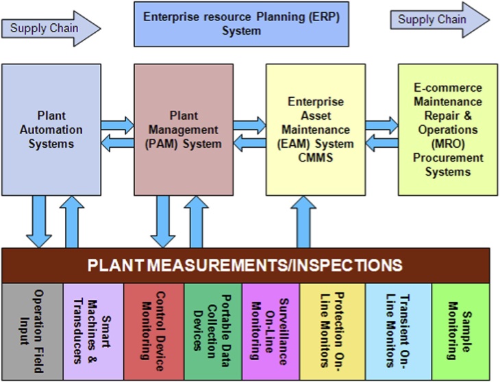
Total productive maintenance begins with a comprehensive program that includes preventive maintenance, planned and scheduled maintenance, predictive maintenance, materials management, training programs, and an enterprise asset management system. In addition, it involves a more quality- focused employee empowerment approach. Reliability centered maintenance also can be embraced in a total productive maintenance approach.
The collection of accurate maintenance and materials management activity data and the trans-formation of that data into information through relevant compilation and presentation are critical for an effective total productive maintenance program. With insight, direction, and involvement, this infor-mation provides the knowledge to guide the total productive maintenance teams in their tactical planning and decision-making processes.
Maintenance software acts as the central collection point for all asset information (cost, perfor-mance, history). Predictive maintenance is a valuable addition to a comprehensive, total plant maintenance pro-gram. Where preventive maintenance incorporates routine machinery servicing, predictive mainte-nance schedules specific tasks, as they are actually required by the equipment.
Recent surveys report that one-thirdd 33 cents out of every dollardof all maintenance costs is wasted due to unnecessary or improperly implemented maintenance. The major cause is a lack of factual data that quantifies the actual need for repair or maintenance of plant equipment and systems. The premise of predictive maintenance is that regular monitoring of the actual mechanical condition of machines and operating efficiency of process systems will ensure the maximum interval between repairs; minimize the number and cost of unscheduled downtime, and improve the overall availability of production systems. Predictive maintenance goes beyond preventive maintenance by using nondestructive testing methods to uncover hidden or pending failures in their primary mode.
A Condition Monitoring layer helps move from the reactive and/or preventive mode of operations to a proactive and predictive environment. Ultimately, it is this linkage between the real-time and operational environment that moves your organization from asset management to Asset Performance Management.
Including predictive maintenance in a total plant management program will optimize the avail-ability of production equipment and greatly reduce the cost of maintenance. A survey of 500 plants that have implemented the process indicates significant improvements in reliability, availability, and operating costs.
Preventive maintenance is a key process in any asset management program. It covers the range of periodic tasks (from inspections and adjustments to component replacement) that are performed on assets at a specific date, on an elapsed time, or preferably, a usage basis in order to keep assets functioning properly.
A preventive maintenance program defines the work plan, entities to which the preventive main-tenance applies, and triggering mechanisms. Multiple triggers may be defined for each entity on a task, and triggers may be:
- Time-based (e.g., daily, weekly, every 45 days, yearly, every 2 years, etc.);
- Based on predefined dates;
- Based on a defined shutdown period;
- Based on other tasks being due (within a specified timeframe);
- Based on user-defined statistics (e.g., meter reading, throughput, temperature, pressure, etc.);
- Future statistic-based trigger dates calculated based on specified average values for the entity or actual values over a specified period of time;
- Future triggers based on work task creation or work task completion;
- On demand.
Reliability centered maintenance (RCM) is a process that determines what must be done to ensure that any plant asset continues to function in the desired manner within its present operating context. There are numerous variations and derivatives of the classic RCM process in use today, most of which are aimed at facilitating the failure modes and affects analysis and developing the appropriate plan of action. These methodologies are often supported by tools such as:
- RCM analysis software;
- RCM forms generators;
- RCM spreadsheets.
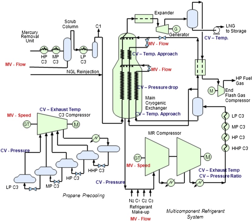
Process control of key units in LNG plants
Inlet facilities
The following describes the special considerations that are necessary for stable plant operation.
In the inlet facility, the level control loop is important as the liquid flows from the slug catcher to the condensate stabilizer system. Attempts to control the level too tightly can introduce unnecessary disturbances in the condensate stabilizer. Appropriate controller tuning strategies like averaging level control tuning can be used to address this issue.
The main control of the stabilizer is to produce a bottom product with acceptable RVP. An RVP analyzer or GC can be used to measure the RVP in real time. This measurement can be performed on a daily basis. An alternative is to use an RVP soft sensor with a pressure compensated temperature (PCT) as the input. The condensate stabilizer bottom temperature is normally used for controlling the RVP.
The feed from the feed drum needs to be maintained as relatively stable. Typically this drum has a relatively large surge volume, and coupled with the tuning of the level controller of this drum, has to accommodate rapid feed rate changes. The stabilizer level is controlled using a feed forward controller cascading to the flow control from the bottom products. The stabilizer overhead pressure control scheme typically is controlled using the capacity controller of the overhead compressors. Alternatively, the column pressure can be controlled by recycling the compressor discharge vapor.
The overall capacity of the LNG plant can be controlled in the back-end LNG product stream, (as is done in the APCI C3MR process), or in the front-end feed gas stream. A stable feed gas pressure is critical in the LNG plant operation, which is typically achieved with a feed pressure control valve. The pressure downstream of the valve is controlled by a flow control valve to maintain the process required by the LNG process and to avoid overpressuring. This can be achieved by an override control system that will reduce feed rate when the maximum operating pressure is reached.
An important consideration in the design of an LNG plant feed system is monitoring the feed gas temperature, since this is needed to prevent hydrate formation. Hydrate formation typically occurs across control valves when the inlet pressure is high and temperature is low. In this case, provision, such as a feed heater, needs to be used for controlling the temperature above the hydrate formation temperature. In most cases, methanol injection points must be provided on the control valve and heat exchanger in case the feed gas temperature unexpectedly drops below the hydrate temperatures.
The main equipments in a typical LNG feed treatment system are the amine system, molecular sieve dehydrators, and mercury removal system. The molecular sieve dehydrators normally are operated in batch mode, with a fixed number in dehydration mode and others in regeneration mode. The sequencing of the operation is automated and the switching is done automatically with a predetermined period for operation during absorption, heating, cooling, and repressurizing. Moisture analyzers with high accuracy to the ppb levels are provided at the outlet of each dehydrator and the combined stream to ensure the gas is completely dried. The regeneration gas flow and temperature has to be controlled to ensure proper operation of this system.
Amine treating system
The amine treating system may use DGA or formulated MDEA to meet the acid gas content required for LNG production. Excessive CO2 will result in freezing in the downstream natural gas liquid (NGL) unit or LNG liquefaction unit, which must be avoided.
To treat the sour gas, lean amine is supplied to the amine contactor at a fixed flow rate. The rate is controlled by a flow controller that is set at a rate high enough to remove the required acid gas content from the feed gas. The composition of the feed gas and treated gas are monitored and the lean amine rate can be set appropriately.
To properly operate the amine unit, the lean loading and the rich loading must be monitored using the procedure recommended by the amine licensor. Rich loading is determined by the amount of amine used. Typically rich loading is determined by the approach to equilibrium (amine to acid gases) which is set at 80% for design cases. This would allow sufficient operating margins to avoid a breakthrough of acid gases. Rich loading in most operation is limited to 0.4 to 0.5 depending on the acid gas content in the feed gas.
The lean amine loadings are different for different types of amine. The lean loading can be controlled by adjusting the steam flow to the reboiler in the regenerator. Typically, the optimum stripping ratio in the regenerator overhead is about 1 to 1.3 (mole steam per mole of acid gas). Alternatively, steam supply can be controlled using amine circulation as the criteria. Typically, in treating a lean gas, such as the tail gas treating unit, the steam requirement can be set based on amine circulation, typically at 1 to 1.3 lb of steam per gallon of circulation.
The amine strength is maintained by the addition of amine or demineralized water. As CO2 tends to react irreversibly with amine to form heat stable salt, amine must be reclaimed on a continuous or periodic basis. The strength of the amine can be maintained by purging the amine system while supplying fresh amine. If DGA is used as the amine solvent, amine can be reclaimed thermally using an amine reclaimer.
Molecular sieve dehydration system
The objective of the molecular sieve dehydrators is to produce a treated gas with low water content suitable for LNG production. Accurate moisture analyzer must be used on each molecular sieve bed and on the common discharge line to monitor the bed performance.
The main control in the molecular sieve operation is the switching valve operation. Depending on the number of beds in operation, the duration of the bed operation under different conditions (absorption, regeneration, heating, and cooling) should be adjusted and optimized as needed to produce a dry gas.
The temperature profile in the molecular sieve beds must be monitored to ensure that the beds are fully regenerated before they are returned to the absorption cycle. The regeneration heater is controlled by fuel gas to maintain the heater outlet at the optimum regeneration temperature.
The water condensate may contain mercury and other hydrocarbons and should be analyzed and disposed of properly.
NGL recovery unit
Most of today’s LNG plants are designed to recover propane and heavier components, which is necessary to meet the heating value specification of the export LNG.
The control philosophy of an NGL recovery is to meet the NGL recovery target and the LPG product specification. Typically, 99 % propane recovery can be achieved and the LPG product should not contain more than 1 mole % ethane. A typical control scheme for an NGL recovery unit is shown in Figure 4.
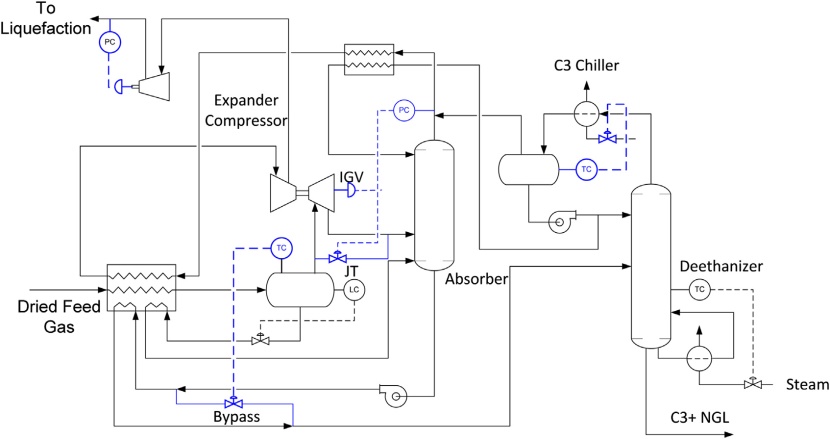
The NGL recovery process requires refrigeration for condensation and for refluxing in the frac-tionation column. The refrigeration requirement is provided by turbo-expansion of at least a part of the feed gas, and externally supplied by propane refrigeration. In some feed cases, propane refrigeration is not necessary if the feed gas is lean and the feed pressure is high.
The column pressure must be maintained stable during normal operation. However, the column pressure can be increased when a high throughput is required. Higher column pressure reduces the pressure ratio across the expander, and hence less refrigeration is generated, which ultimately results in lower recovery.
There are two control devices that can be used for column pressure control: the inlet guide vane (IGV) valve of the turbo-expander, and the JT bypass valve. Normally, the absorber pressure is controlled by closing or opening of the IGV valve. Only when the IGV valve is fully open and the column pressure is still dropping, the JT valve will open to maintain the pressure. This typically occurs during plant startup or shutdown operation.
The residue gas pressure is controlled by varying the speed of the residue gas compressor as necessary to meet the LNG liquefaction plant inlet requirement.
Another critical operating parameter is the temperature of the expander suction drum temperature. This temperature determines the composition and amount of NGL condensed in the drum. Lower temperature will reduce the flow rate to the expander while increasing the liquid from the suction drum that is eventually fed to the column. Conversely, higher temperature will increase the flow to the expander and reduce the liquid to the column. Changing this temperature will impact the control of the expander and the vapor traffics in the columns.
One of the control options on controlling the expander suction drum temperature is to bypass the absorber bottom. The absorber bottom is used to provide cooling to the feed gas, and bypassing this stream will reduce the cooling effect on the feed gas, increasing the chilled temperature. The operation will reduce the feed temperature to the deethanizer, which will indirectly reduce the propane chiller duty.
Another measure that needs to be monitored is the deethanizer overhead temperature. Decreasing the overhead temperature will increase the reflux to the deethanizer, which will result in better separation and higher NGL recovery. The reflux drum temperature can be controlled by adjusting the propane flow to the chiller.
The LPG product quality is controlled by adjusting the steam flow to the reboiler in the deethanizer column. The C3+ liquid is typically analyzed periodically, which is used to set the bottom temperature.
Fuel gas system
The fuel gas system is designed to supply the fuel gas to the gas turbines, fired heaters, steam generators, and other users at the required pressure levels. This system typically consists of at least two pressure levels. The sources of the fuel gas can come from different sources. It can be from the feed gas, the residue gas, storage tank boil-off gas, or other off-gases in various parts of an LNG plant.
The fuel gas control system has to ensure that the dew point criteria and the fuel gas heating value criteria are maintained to be within specifications. Depending on the type of gas turbine, the Modified Wobbe Index (MWI) may have to be maintained within a certain range. Also, for the more efficient aero-derivative DLE (Dry Low Emissions) gas turbines, the rate of change of fuel gas properties has to be within certain limits. This is important for the gas turbine controls to ensure proper burner operation.
The main objectives of the process control schemes for the fuel gas system are as follows:
- Maintain adequate fuel gas supply. This requires adequate backup supply of fuel gas sources in case of a surge in fuel gas consumption during transient conditions;
- Maintain the temperature and Wobbe Index. It is critical to prevent any condensation in the system. The temperature has to be maintained at a superheat state, avoiding the condensing temperature. Also, the fuel gas Wobbe Index has to be within a certain range for the gas turbine to operate properly. This may require blending with lean fuel gas or with nitrogen;
- Mitigate rate of change of fuel properties. This could be important to ensure proper burner operations during transient conditions. Sudden changes in the fuel compositions may result in gas turbines misfire, resulting in a shutdown of the gas turbine.
Pressure controllers could be cascaded to flow controllers, which are tuned for fast response. The pressure controls could also be set up with staggered setpoints or split range control schemes to manage the various makeup sources for the fuel gas. One of the challenging issues for control is the transition from one fuel source to other. The regular PID control scheme may not react fast enough to prevent a drop in the header pressure. Feed-forward schemes may be required to avoid an unacceptable drop in header pressure. Appropriate advanced regulatory control schemes to operate under this scenario can be developed and tested using dynamic simulation.
Fuel gas temperature can be controlled by heating using a steam or electric heater. A temperature controller is normally used, with the setpoint set with a good margin above the dew point. If frequent changes in the fuel gas composition are expected, the dew point calculation can be automated based on the fuel gas composition.
One way to mitigate problems during transition is to ensure that the proper instrumentation and control schemes are set up to handle it. Normally, a Wobbe meter would be needed to measure the properties of fuel gas for the burner control scheme. The positioning of the Wobbe meter can be tailored to ensure that the deviation is within acceptable limits. Dynamic simulation can be used to determine the appropriate location of the instrumentation and control logic that is effective under all transitions.
Liquefaction system
The liquefaction system is the heart of the LNG plant, because it cools and condenses the pretreated natural gas to produce LNG. This system is characterized by extensive heat integration utilized to enhance process efficiency. The process temperatures at various points need to be maintained to ensure proper temperature approaches for heat exchangers. Another important requirement here is the reliable operation of the turbo-machinery used to compress the refrigerants in the system. The specific aspects of the liquefaction process control scheme depend on the process technology that is used. There are several liquefaction process technologies available on the market. These include the APCI mixed refrigerant process (C3MR), cascade refrigeration process, the Shell DMR process, among others. The discussion will be targeted mainly at the former three processes, since these are used in the majority of the operating LNG plants and LNG plants under construction.
The main objectives and challenges in the control of liquefaction section of the LNG plant are:
- Ensuring that condensing and subcooling are maintained for the LNG stream. This is achieved by controlling the LNG temperature, directly or indirectly;
- Ensuring the reliable operation of the LNG plant with changing ambient conditions and feed composition. The specifications for LNG and NGL products have to be met under various feed gas compositions;
- Proper operation of the turbo-machinery strings, which is critical for the reliability of plant operation. This includes surge protection for the refrigeration compressors;
- Maximizing the LNG production or maximizing efficiency under fixed LNG production.
The selection of appropriate controlled variables and manipulated variables is important to ensure adequate operability of the LNG plant. Methodologies to perform this selection have been reported by Jensen and Skogestad and Singh et al. This is based on optimizing certain objective functions and evaluating the degrees of freedom in the LNG process. This methodology was utilized to develop a regulatory control scheme for the LNG plant.
Control of refrigeration processes
Since the LNG processes utilize principles of refrigeration systems in their design and operation, the control philosophies from traditional refrigeration processes are applicable. A typical singlestage refrigeration process normally consists of a chiller, compressor, condenser, and surge tank. The chiller cools the hot stream and evaporates the refrigerant in the process. The liquid from the accumulator goes through a JT valve to the chiller. A schematic of the typical refrigeration process with the control schemes is given in Figure 5. The main control loop here is the temperature of the cooled stream, which is maintained by controlling the pressure in the chiller. This can be achieved by manipulating the compressor speed by implementing a cascade loop.
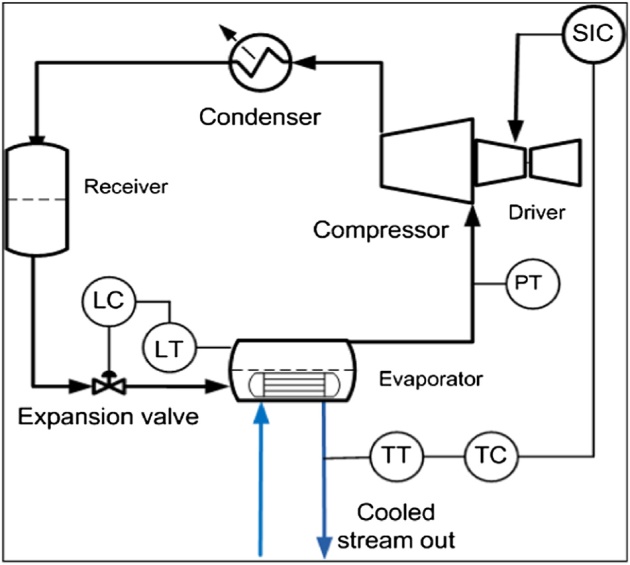
Either the temperature itself or the chiller pressure can be the process variable for the master loop. The rest of the process essentially floats on the chiller duty. The chiller level is normally maintained using the JT valve. Multistage refrigeration processes are used to enhance the efficiency of the process. The basic control philosophy in this case is still the same as for a single-stage process. A systematic procedure to analyze the available degrees of freedom in refrigeration systems is given in Jensen and Skogestad.
Control of liquefaction unit
The main control objective in the liquefaction section is to ensure that the condensing of natural gas to form LNG and subcooling of LNG is achieved under all conditions. The other important consideration is to maintain the desired plant capacity. These two objectives should be achieved while rejecting disturbances like ambient temperature and feed composition. The capacity control can be achieved by feed rate control or back-end LNG flow control. The cascade refrigeration process normally uses the first, whereas the APCI C3MR process utilizes the second. Instead of feed flow control in the front end, pressure control in the front end can be utilized as an alternative. This scheme can be designed to take as much feed gas as needed to produce LNG at a particular temperature.
It is important to maintain the LNG temperature to ensure condensing of natural gas and any amount of subcooling that is required. If the LNG is too warm, the boil-off gas vapor generation will exceed the capacity of the BOG system, resulting in flaring. For cascade refrigeration processes, the LNG temperature is maintained by maintaining the pressure in the chillers, as in a typical refrigeration process. This is controlled by cascade control with the refrigeration compressor speeds. The condensing pressure in the back end is also controlled in this case.
For APCI C3MR processes, if independent control of production and temperature is not desired, the LNG temperature is controlled by varying the production rate. The refrigeration capacity is adjusted by the compressor speeds and JT valve positions (warm and cold). The amount of refrigeration is determined by these handles. This will also set the production rate to maintain the LNG temperature. The compressor pressure ratio is also controlled using these variables. The ratio of liquid mixed refrigerant (LMR) to vapor mixed refrigerant flow rate is an important variable in the C3MR process and is controlled using the JT valve positions.
For independent control of LNG temperature, temperature can be controlled by manipulating the amount of refrigeration in the system as shown in Figure 6.
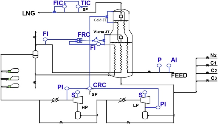
This can easily be achieved by manipulating the MR compressor speed. Other parameters like Warm JT valve can also be used as a handle to accomplish this. Increasing the compressor speed would lower the LNG temperature for a given production rate. The LNG production can then be set at the desired value that is independent of the temperature. The cold JT valve can be used to maintain the ratio of liquid MR to vapor MR (Figure 6).
Compressor and gas turbine control
The refrigeration compressors are critical equipment in any LNG plant and their proper operation is important for the overall reliability of the plant. The control schemes used for these compressors depend on the driver that is selected for them. A vast majority of the drivers used in the LNG process are gas turbines, including frame-type turbines and aero-derivative turbines (steam turbines and electric motors are used as drivers, but rarely). The capacity control of these machines is accomplished using compressor speed as a variable. The compressor speed can be used as an independent variable and set by the operator. Alternatively, the compressor suction pressure is cascaded to the speed control to maintain the capacity. This way, the machine speed, and hence the load, change depending on the refrigeration load.
There are different options as to the implementation of this capacity control function for refrig-eration compressors. This could be implemented in the plant DCS system or can be included in the compressor control package from different vendors. The second one is the preferred option (as opposed to DCS-based capacity control). This is due to the fact that the capacity control interacts with the antisurge control, and this has to be accounted for via a loop decoupler for improved control performance.
There are several important capabilities that are required in a well-designed compressor-driver control system. Some of the key ones are:
- Capacity control. A well-designed capacity control system is important to ensure the smooth operation of the LNG process. The selection of the controlled variable is important here;
- Antisurge control. An effective antisurge control system is critical for the protection of refrigeration compressors and to prevent damage due to surge;
- Load balancing. Load balancing is important to enhance the operation of compressors in parallel. This helps to ensure that both machines operate with close to equal loads, thus preventing the possibility of one machine operating in recycle (unloaded) with the parallel one fully loaded;
- Loop-decoupling. The interaction between antisurge and the capacity control can be significant. This is due to the fact that opening the antisurge valves affects the pressure and changing speed varies the antisurge control setpoint (flow requirements). Hence, loop-decoupling is important to ensure the interactions between these do not result in persistent oscillations;
- Override control. The override control of suction or discharge pressure should be considered to prevent undesirable operating conditions. These control overrides normally utilize the antisurge valve openings to prevent any abnormal suction or discharge pressures;
- Load-limiting control. This is relevant for the cases where the driver power becomes a limiting factor. In these cases, the load on the machines has to be maintained below the upper limit to prevent driver overloading (which could result in a turbine underspeed trip). This can be accomplished using load limiting controls that use handles like suction throttling valves or other variables.
The various features of the compressor-driver control system are shown in Figure 7. These ca-pabilities may be provided by a control system vendor specialized in control of compressor systems.

These could be used to separate the system from the plant DCS system. Certain DCS systems also provide functionality for implementing these functionalities. The final decision has to be made considering a number of project-specific factors.
Antisurge control systems
The antisurge control system is critical in ensuring the safe operation of the refrigeration compressors in the LNG plant. The refrigeration compressor stages usually run at high power levels, which can encounter severe damage if operated in the surge region. Operating the compressor in the surge region can result in intermittent and rapid flow reversals, which can severely affect the impellers.
Although surge prevention is paramount, other undesirable operating conditions like stonewall also need to be avoided. Also, the compressor speed has to be maintained within acceptable ranges to prevent unplanned shutdowns. The safe operating region for a compressor is shown in Figure 8. The acceptable operating range for a compressor is set based on these operating constraints and certain chosen margins of safety.
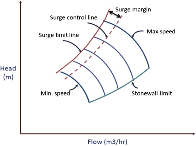
The main objective of the antisurge control system is to ensure the compressor stages operate to the right of the surge limit line in the map (which ensures flow greater than surge flow). A surge control line is selected, with a predetermined margin (surge margin) and the control scheme is set to maintain the operating point to the right of this surge control line. The selection of the surge margin has to be based on several factors, including:
- Control functionalities that are utilized (derivative response, recycle trip response, etc.);
- Shape of the compressor curve, especially the head rise to surge. Having flat curves in the surge region would necessitate using higher surge margins for control;
- Discharge and suction piping volumes. Larger discharge volumes may require higher surge margins;
- Antisurge valve characteristics. The size and speed of the antisurge valve also has an impact on the selection of surge margin. A slower valve may require more margins for control.
The surge control margin will have to be developed empirically based on actual field testing. Reliable initial estimates can be obtained using dynamic simulation analysis.
The control functionalities used for the antisurge control are important in deciding the performance of the surge protection system. The following are some of the capabilities that are desirable in the antisurge control systems:
- Normal Proportional-Integral (PI) control. The base antisurge control is usually a proportional and integral-based control response. This looks at the distance from the surge control line (SCL) and tries to maintain the operating point to the right of SCL;
- Derivative response. The derivative response evaluates at the speed at which the operating point moves toward the surge control line. Based on this, the antisurge response is varied to enhance the control performance;
- Recycle trip response. The recycle trip response is used once the operating point moves to the left of the recycle trip control line (closer to surge limit line). The antisurge controller output is proportionally opened in this case to bring the operating point back to the right of SCL;
- Surge counter reset. The surge counter is used to evaluate the number of times the surge happens. This is used to reset the surge margin and move the surge control line to the right to prevent further surge events.
Gas turbine control
The control of gas turbine drivers is handled by the gas turbine vendor package and not in the scope of plant DCS. It is still important to understand the various control features for effective LNG plant design and operation. The main features in the gas turbine controls are listed here.
- Speed governor. The gas turbine speed control is the most important loop because this sets the refrigeration compressor speeds and hence the capacity. This could be an independent variable that is set by the operator (alternatively APC system) or could be cascaded to the suction pressure for capacity control. The speed governor normally manipulates the fuel gas flow to the turbine, which delivers varying shaft power. This is a PID controller with all three modes active and tuned for fast response;
- Exhaust temperature control. The exhaust temperature control is normally an override loop that will act on the fuel gas if the limit is reached. This loop should not be active normally since this is a physical limit;
- Acceleration control. Acceleration control is used to ensure that the gas turbine rate of change of speed does not vary beyond safe limits. This is normally applicable in transients like startup to limit thermal stresses due to overacceleration. During normal operation, this may become active to prevent rapid overspeeding in the event of a sudden load reduction;
- Other. Other control functionalities are also present in a gas turbine control package, which are important from a mechanical and machine integrity perspective.
Storage and loading
The storage and loading section of the LNG plant consists mainly of LNG storage tanks, the boil-off gas compressors, the LNG loading pumps, and the loading system.
The main objective of the process control system here is to maintain the LNG storage tank pressure to prevent any flaring due to overpressuring of the tank. The vapors from the tank are fed to the BOG compressor, which then compress it and sends it back into the liquefaction process or uses it as fuel gas. The tank pressure has to be controlled by manipulating the flow of BOG vapors. This can be accomplished in two ways. If the BOG compressor is variable speed or variable IGV machine, speed or IGV control could be used to control the pressure. On the other hand, if it is a fixed speed machine, discharge valve throttling is used to control the pressure.
The control of tank pressure is also impacted by the liquefaction system performance, especially the LNG temperature. If the LNG product is too warm, excess vapor generation will overload the BOG system. Hence, specifying and maintaining the correct setpoint LNG temperature control is important for efficient plant operation.
Advanced process control and optimization of LNG plants
APC has established itself as a widely used technology in process and other industries. Currently, there are hundreds of industrial units that benefit from this technology. The main reason for its popularity is the ability to run plants at optimal conditions while handling various operational constraints and disturbances. Model predictive control (MPC) is the most popular advanced control technique. MPC consists of a model capable of predicting the behavior of key variables in the plant. Adjustments are made to the corresponding manipulated variables to keep the control variables tracking close to their desired target values. These target values are obtained from an optimizer that aims to increase the profit function. A typical MPC application resides on top of the regulatory control layer and sends the setpoints to the PID controllers in the plant.
There are many benefits to be derived from application of APC to an LNG process. LNG plants are characterized by operational challenges including varying ambient conditions, heat integration, and product quality constraints. For LNG plant owners, the main benefit from APC is product maximization, which increases the operating profit. Other benefits like increased process efficiency, increased NGL production, and reduced operator intervention are also valuable. A properly designed APC application can achieve these objectives with reasonable capital investment.
APC has been applied extensively in refining and petrochemical industries in the early days of this technology. There was not much interest in applying advanced control to LNG units then. This has changed in recent years, and different applications of APC to LNG processes are being reported. Recently, Shell has reported applications of APC to the LNG processes based on the Shell DMR process. Application of APC to a LNG train in Qatar was reported by Aspen Technology. More interest in the application of APC to LNG plants is expected in the future. This is due to changing market conditions, whereby operating plants will be able to sell excess LNG production in the spot market. This provides significant economic incentives in maximizing the existing plant potential. This also raises the issue of tailoring the LNG quality to the appropriate market and changing the product mix based on economics. APC is a proven tool to achieve all these objectives.
Model predictive control technology
Model Predictive Control (MPC) is a class of methods that uses an explicit model for predicting future response of the plant and for control. The variables in MPC are divided into manipulated variables (MV), which are changed to maintain the controlled variables (CV) within constraints. This is accomplished in the presence of disturbance variables (DV) that upset the process. The plant model that is used for MPC is an empirical model derived from performing step tests in the plant or a dynamic model. This empirical model is developed from the step test data and model identification tools. At each time step (every minute or so) MPC solves an optimization problem to calculate the best steady state operating point for the plant. This optimization is normally formulated as a linear or quadratic program.
Once the optimization is solved and the optimal steady state operating point is determined, the best method to reach the target is calculated. This calculation is done based on the empirical model and the current operating point. The first manipulated variable move of this trajectory is implemented and the whole calculation is repeated in the next time step with the new measurements.
Advanced process control implementation steps
The main steps in the implementation of APC are detailed here.
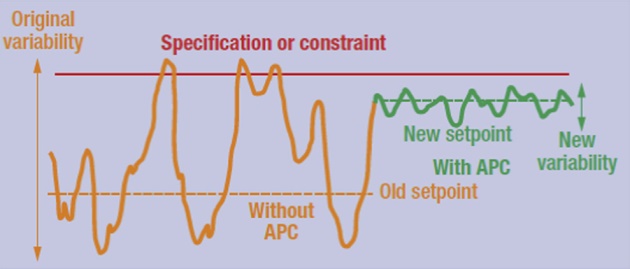
- Economic benefit analysis. The first step in the implementation of APC is the evaluation of the economic benefits that can be achieved from APC. This is done using statistical methods based on the plant operating data. In this case, the performance of the plant is analyzed in terms of the variability in the key variables, normally measured in terms of standard deviation. The benefit of implementing advanced control is to reduce the variability in these key constraints. This allows the operation of the plant closer to the constraint, thus improving economic gain (Figure 9);
- APC Controller design. In this step, a design of the controller is developed. This is based on the operational expertise of the plant personnel and operators. The main objective here is to identify the various capacity limiting constraints and the economic benefits from optimization. Also, the main controlled variables, manipulated variables, and the disturbance variables are identified at this stage. The need for any inferential variables is also determined here;
- Plant pretest. This step involves a thorough review of the existing plant regulatory controllers and analyzers. The APC sends the setpoints to the base regulatory controls. The tuning of these controllers has to be verified and improved. Also, the reliability of any analyzers used in the plant will be established in this stage;
- Plant step test. Here, the main objective is to develop empirical models for the APC controller. This can be done in the plant or a dynamic simulation model. The models developed can be updated using closed loop identification at a later stage during commissioning;
- APC controller development. In this step, the data collected from the plant step test is used to identify empirical models for the controller. Also, the controller is configured with the initial tuning parameters and limits for field implementation;
- APC commissioning. In this step, the developed APC controller is implemented in the plant. The controller is tested in open and closed loop modes. The performance of the APC under various disturbances and other operational scenarios are verified;
- Operator training and post implementation review. The operators have to be trained to understand the plant operation with APC. This is done in this stage of the project. Also, the actual benefits derived from APC are estimated in this step using the plant data after implementation.
Benefits and challenges in applying advanced process control in LNG plants
There are several key benefits to be derived from application of APC to LNG plants as detailed here.
- Maximize plant throughput. The main benefit of APC is to maximize the LNG production by operating at the capacity limiting constraints. These could be hydraulic, equipment, or other constraints. These constraints vary with changing conditions like ambient temperature, feed composition, and so on;
- Enhance plant efficiency. There are two different objectives to be considered in this case. First is to minimize the plant fuel consumption to increase the net LNG production with a fixed plant feed rate. The second is to minimize the energy consumption for the operation of energy-intensive unit operations like separation columns. This can be achieved by operating the column under optimal conditions;
- Improve yield of valuable products. A typical LNG plant has products like NGL, propane, or butane, in addition to LNG. The benefit of applying APC here is to increase the production of more valuable product by operating at the best constraints. This is accomplished while honoring the product quality;
- Maintain product quality. It is important to meet the product specification for LNG and NGL products to minimize product waste. For LNG, the HHV and Wobbe Index are important parameters. For NGL, the RVP has to be maintained. The APC can move the operation closer to the limits of these specifications to improve the overall optimum;
- Improve stability and reduce variability. The APC reduces the overall variability in operation due to changing ambient conditions or other disturbances. This indirectly helps to minimize abnormal events like flaring;
- Reduce operator intervention. In the operation of a typical LNG plant, the operator has to make frequent adjustment to the plant operation with changing ambient temperature or other operating conditions. APC eliminates the need for this and allows the operator to focus on other important tasks;
- Enhance operational flexibility. One of the key benefits of APC is the ability to incorporate market conditions to determine the optimum product mix. This could imply that under certain market conditions, maximizing the production of NGL would be more valuable than LNG or vice versa. APC objective functions can incorporate this to reach an overall economic optimum.
There are certain features of LNG plant operation that are challenging and will have to be considered in the APC controller design. These include the following:
- Ambient temperature variation, both typical day-night cycle and sudden changes due to extreme weather conditions. This affects the gas turbine operation and hence the LNG process and will have to be handled by the APC;
- Feed gas composition changes, with changes from lean feed gas to rich and vice versa. The APC should be able to change the various operating conditions, including separation column variables to handle transitions likes this;
- Strict limitations on temperature differentials in plate and frame exchangers, which needs to be maintained during dynamic transitions;
- Ensuring proper CO2 and H2O removal for feed to liquefaction units to prevent freezing in downstream equipment;
- Variations in feed gas supply temperature and pressure, which acts as disturbances to the APC;
- Ability to accommodate ship-loading, which results in extra boil-off-gas return to the liquefaction section of the plant;
- Other unmeasured disturbances that can impact the LNG process.
dvanced process control for individual units in LNG plants
Upstream and inlet facilities
The upstream and inlet facilities in the LNG plant include the slug catcher, the inlet stabilizer, and associated equipment. This does not include the offshore equipment, which is usually implemented in a separate controller. The slug catcher does not have significant APC benefits, other than to control the level and to use the buffer capacity efficiently.
The main area of application of APC in this area is to the stabilizer columns. The inlet stabilizer is a key unit that removes the NGL from the inlet stream. The main control objective here is to maintain the C5+ concentration in the overhead and the RVP of the bottom product. The APC can be beneficial in the control of RVP, which can be pushed to its high limit, thus increasing the condensate production.
Another application of APC in this unit is to reduce the energy consumption. It is beneficial to operate this column at a low pressure, thus reducing the energy consumption. This pressure is con-strained by the column flooding, control valve openings, or the capacity of the overhead compression system. Further economic benefits can be derived from increasing the stabilizer throughput. This is especially beneficial in the case where stabilizer capacity is the limiting factor in increasing the plant production.
Acid gas removal unit
The objective of an acid gas removal unit is to remove the CO2 and H2S in the feed gas to a very low concentration before sending the gas to liquefaction. This is achieved using absorption with MDEA or other solvents. The solvent is regenerated in the regenerator column and recycled back to the absorber. The main benefit to be derived from applying APC to the acid gas removal unit is the improvement in control of CO2 concentration in the column overhead. This is achieved by means of reduced variability via model-based control. The reduction in variability in CO2 concentration makes it possible to minimize the energy consumption in the column reboiler. Normally, steam or hot oil is used for reboiler energy supply. Other benefits include the reduction in amine recirculation rate, which can reduce the solvent losses. The main manipulated variables that are used to achieve these objectives include the lean amine flow rate, the reflux ratio setpoint, and the regenerator bottom temperature.
The benefits to be gained from applying APC to the acid gas removal unit may not be significant compared to the other units like liquefaction. For plants with a sulfur recovery unit, increasing the sulfur recovery using APC could yield significant economic benefits. A comprehensive benefit analysis would be needed to evaluate this and to make a decision to include this unit in APC.
The other main components of the feed treatment system in LNG plants are the molecular sieve units for dehydration (to ppm level) and mercury removal beds. There are no significant economic benefits to be gained from applying APC to these units. There could be cases where the water or mercury composition in the feed gas at the outlet of these can be a capacity limiting constraint. The composition could be then included as a constraint in the APC.
Liquefaction system
The liquefaction system is the main unit in the LNG plant and is also the unit where significant benefits can be derived from APC. The design and specific variables used for APC in a liquefaction system are dependent on the liquefaction technology that is used. The application of APC has been reported for the APCI C3MR process, Conoco Phillips Optimized cascade LNG process, and Shell DMR process.
The main APC objectives in the liquefaction system are to increase capacity and optimize the overall plant efficiency. All LNG processes are affected by the ambient temperature, and hence the need to push the plant capacity to the maximum at any ambient is applicable to various LNG tech-nologies. The plant efficiency is enhanced by operating the plant at the optimal conditions that minimize the fuel usage for the drivers.
The capacity limiting constraints could be different for different LNG processes. For the plants based on the same LNG process technology, individual plants have unique constraints in addition to the generic constraints. The main constraints applicable to all processes are the limitations in the refrigeration compressors and drivers (gas turbines or other), including turbine power or compressor conditions (flow limitations, speeds, discharge pressure, and temperature). Further, all LNG plants are characterized by limits on heat exchanger temperature differentials, which should be included as constraints in the APC design.
For the C3MR process, the MR compressor/driver and propane compressor/driver variables are key constraints. Also, LNG temperature is one of the key controlled variables. These are maintained by mainly varying compressor speeds or MR compositions and flow rates. The design of APC for this process is discussed in more detail later.
For the cascade refrigeration process, optimal distribution of load between various refrigeration cycles can be maintained using APC. This load balancing between the various refrigeration systems is very important to maximize the capacity under all conditions. The key variables that are used to achieve this are the suction pressures for the refrigeration compressors. In addition, other load-balancing handles are normally provided, which can be used to optimize the plant capacity.
The other main consideration in this system is maintaining the product quality for LNG (HHV). This is discussed further in the next section. Also, the BOG compressors need to be able to handle the BOG return from the LNG tank. This means that the LNG product sent to the storage tank has to be at an appropriate temperature and the vapor return at an appropriate pressure, such that the BOG vapor return compressors are able to handle the return vapors from the tank.
Scrub column and fractionation units
There are significant economic benefits to be gained from using APC in the NGL and fractionation section of the LNG plant. This is the area of the plant that dictates the LNG properties and the split between various products. The main objectives of the APC controller in this unit are:
- Determine the right operating LNG/NGL split. The APC can incorporate the market values of LNG and NGL to determine the optimum allocation of one versus the other;
- Control the product qualities. The APC can be valuable in maintaining the product qualities in the NGL and fractionation systems and hence the final LNG product quality;
- Minimize the energy consumption. Further operational optimization can be achieved by minimizing the energy consumption in the columns in this section.
The scrub column (Heavies removal column) is first used to remove the heavier components in the feed stream, before it is sent to liquefaction. There are two main objectives of APC in this column.
- Maintain the overhead composition of the C5+ below limit. This is important to ensure that heavier components do not cause freezing in the liquefaction;
- Depending on the market conditions, the remaining objective of the scrub column could be different;
- If the NGL is a more valuable component, then the bottoms from the scrub columns can be maximized with the overhead composition maintained such that the LNG product meet its HHV spec;
- If it is more important to maximize LNG, the HHV of the LNG can be pushed to the maximum allowable limit by sending heavier components to the overhead of the column.
The LNG plant fractionation section may or may not be present depending on the facility and plant design. A typical fractionation system consists of deethanizer, depropanizer, and debutanizer. The following key objectives are to be considered for APC on this unit.
- Maintain the operating temperature and pressure values for each column;
- Maximize the recovery of propane and butane in the overhead of the columns;
- Maintain the RVP spec for the final bottom product;
- Minimize the energy consumption to optimize efficiency.
APC has been applied extensively to fractionation columns, and the design of the controller for these columns is well established.
The main controlled variables in the NGL recovery section are the product qualities; hence, reliable measurement for these is important. It is preferred to have online analyzers to measure these in real time. Even if these properties are measured, the measurement may be very infrequent. It is beneficial to develop and use property inferentials (soft sensors) for use in APC. These inferentials are used to determine a product quality variable as a function of other measured variables. These can also be used along with the analyzers to provide more frequent updates for control.
If the plant has a DOMGAS and LPG unit, further economic benefits can be gained from application of APC to this section. The main benefit in this unit is ensuring the quality and increasing the recovery of the LPG, which is a sellable product. Additional optimization can be achieved by coordinating APC here and in the fractionation section APC, thus maximizing the overall facility LPG recovery.
Process control and automation in LNG import terminals
There are several challenges in designing the automation and control layer in LNG terminals. These include tough environmental regulations, volatile market conditions, and operational challenges. The main components of the LNG import terminal automation system include the process control system (PCS), the safety system, the fire and gas system and the emergency shutdown system (ESD).
Basic process control systems
The process control in LNG terminals can be divided into three distinct areas of operation:
- LNG ship unloading;
- LNG tank operation;
- LNG send-out and vaporization.
The LNG ships unload their cargoes to the LNG storage tanks using the ship pumps. The unloading rate is controlled by the ship. The operation of LNG ship pumps, unloading arms, BOG compressors, and vapor return blowers are coordinated during unloading. There is a significant increase in the vapor return during ship loading. The operator will have to set the number of BOG compressors based on the ship unloading rate to maintain the system pressure. Normally, a Jetty unloading and mooring PLC will monitor the unloading line and automatically stop unloading when unsafe conditions are detected.
The LNG storage tank pressure normally is controlled to prevent it from going too high or low. When the tank pressure goes high, the BOG compressors will be manipulated to increase the flow and bring the pressure down. When there is no ship loading, the tank pressure can go lower than the desired values. This is prevented by introducing vacuum breaker gas on pressure control. In addition to this, the instrumentation with alarms is provided to monitor levels, temperatures, and pressures in the LNG storage tanks.
During ship unloading, the BOG can be returned to the ship using return blowers. The pressure of the vapor return will be maintained by pressure control at the blower outlet. The return vapor will also have to be desuperheated on temperature control to maintain appropriate temperature. The BOG gases, which are compressed, are normally used as a fuel gas supply for the submerged combustible vaporizers (SCV). The remaining BOG can be condensed and recovered in the BOG recondensors. The fuel flow to SCV will vary based on the demand and is set to maintain the pressure. The pressure control at the discharge of the BOG compressors open the valve to the recondensor based on the total vapor flow.
The LNG is sent to the vaporizers using the send-out pumps on flow control. The temperature at the outlet of the vaporizers is monitored to ensure a sufficiently hot stream. This product natural gas is then delivered to the pipeline. A pressure controller is used to maintain the back pressure in this line.
Terminal information management system
The main role of the Terminal Information Management System (TIMS) is to ensure operational safety and efficiency and to provide integration between the corporate management systems and terminal process control system. This is especially important for LNG receiving terminals because they are a crucial link between the gas field and the consumer. Also, there is a tight linkage between terminal scheduling and operating orders, with cyclical switching between loading and unloading. This coordination is more important with the changing market conditions, where the LNG terminals are serving more customers. The application of an operating information system (OIS) for the Incheon LNG terminal was discussed by Lee and Yang. The OIS in this case included several advanced functions including online monitoring and reporting, data reconciliation, PID autotuning, and operator support.
The main functionalities of the typical LNG TIMS, as shown in Figure 10, are:
- Supply chain management. The objective of SCM is to ensure proper delivery of timely information for supply chain optimization. Several functions like cargo tracking, energy balance, and terminal scheduling are included in this;
- Operations management. Assists the terminal operations by providing the right information and the operating parameters;
- Asset management. Assists the maintenance personnel with maintenance data and schedules;
- Compliance management. Helps to ensure that the regulatory reporting requirements are met by facilitating reporting;
- Business management. Ensures alignment of business processes to meet stakeholder requirements.
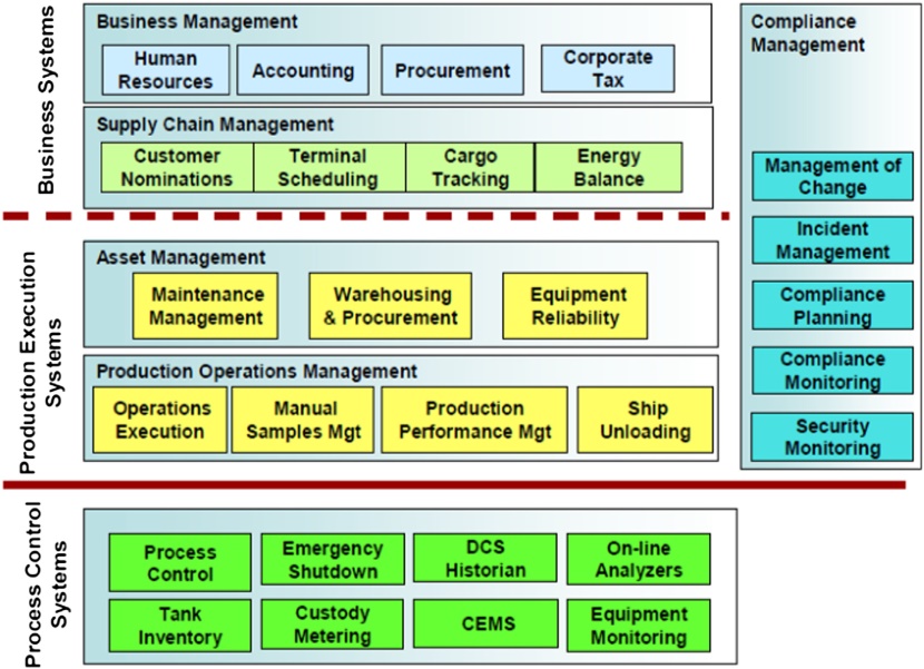
Optimization in LNG receiving terminal operations
Several options are available to enhance the reliability and efficiency of the LNG terminal operation. These include the traditional methods like process control enhancements and advanced process control. Some of the other possible options in this regard are:
- Basic process control and advanced control. This entails integration of various control systems so that they can be monitored and operated from common consoles;
- Operator training with simulators. The improvements in basic control systems mean that there are less frequent upsets. Hence, the operators have to be trained to handle emergency situations using operator training simulators;
- Facility condition monitoring. Enables early detection of fault signs and response to the same. This increases the reliability of gas production and reduces maintenance costs. For example, this allows detection of excessive vibration from cryogenic power generation and LGN pumps before any failure, thus enabling early measures to correct the problems;
- Tank operation planning system. Used to determine a tank operation plan that efficiently balances the costs including LPG for calorific adjustment and electrical power, while honoring the operating constraints. This system takes tank level, tank calories, cargo schedule, production schedule, etc., as its inputs and outputs the optimal LNG discharging and receiving plans;
- Productivity management system. Utilizes the operating and productivity data for four main types of equipment in the LNG terminal: LNG pumps, BOG compressors, seawater pumps, and LNG vaporizer units. This is then used to provide operation support that improves the productivity of the entire terminal.
A very important economic objective is the efficiency of operation of the LNG import terminal. This is achieved by reducing the power consumption for various equipment like BOG compressors, LNG pumps, and seawater pumps (if used). Alternatively, efficient operation of SCV can increase the overall LNG terminal operational efficiency.
Case study 1: advanced process control for APCI C3MR LNG process
The evaluation, design, and implementation of an APC controller for the APCI C3MR process is discussed in this case study. The APCI C3MR process is the most common LNG process used in the industry. Detailed descriptions of this process are available in the literature. The case study considers the liquefaction and the heavies removal sections of the plant. The application of APC to condensate stabilizer system was presented in Mokhatab and Poe.
Estimation of benefits from APC implementation
A feasibility study is first conducted to identify the economic benefits from APC and the potential implementation issues. The main benefits identified included maximizing the LNG and LPG production and enhancing the overall plant efficiency. Other intangible benefits like stabilizing plant operations are also considered valuable.
The scrubber column APC objectives could be different, depending on the relative LNG and LPG prices. If the LPG is more valuable, the objective is to maximize the LPG production. Otherwise, it is more beneficial maximize the C3+ content in LNG (with due consideration of the LNG HHV spec). For the plant under consideration, LPG maximization was beneficial. Hence, the main objectives of APC for the scrubber unit include the following:
- Keep C5+ in the overhead below the specified limit to prevent freezing;
- Keep the overhead stream HHV within range;
- Maximize the C3 in scrubber bottoms.
The main objective of the APC in the deethanizer is to ensure that the overhead stream meets the specified limits. This stream is send to liquefaction or fuel gas for further processing.
The liquefaction APC is where the majority of the economic benefits are realized. The main objective here is to maximize the LNG production. The LNG HHV has to be maintained within the specification range. Also, the LNG has to meet the required specifications; including the one that the amount of C1 should be higher than the specification value. If the production is constrained by the market, the efficiency has to be maximized to realize the benefits. The efficiency for the C3MR process is specified by Specific Brake Horse Power (SBHP). Alternate measures of efficiency including the ratio of the amount of fuel gas to the amount of LNG can be utilized for optimization purposes.
The APC benefit estimation is based on reducing the variability in plant operation, hence pushing the key variables to the constraints (Figure 11). The standard deviation of the main controlled variables before APC implementation is determined from the historical plant data. The reduction in standard deviation by means of APC is known from other similar implementations. This difference in standard deviation can be translated to an economic benefit and can be determined (Figure 9). For calculating the benefits from LNG production maximization, the percent increase in the LNG is determined based on the reduction in standard deviation. For example, for a plant with 10 MTPA LNG production rate and 1 % increase in LNG production, the benefits can be calculated as Economic Benefits = 10 × .001 × (LNGP — GIPP), where LNGP is the price of LNG and GIPP is the price of gas in place (GIP).
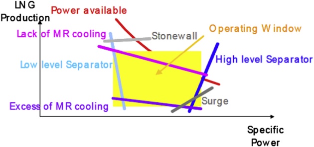
The other main economic benefit for this case is in maximizing the NGL production by three means:
- Reducing C3+ content in LNG up to specification;
- Increasing C2 content in C3 product up to specification;
- Pushing the amount of condensate in LPG C4.
The benefits from these actions can be calculated by determining the extra NGL that is produced. For this, the variability in the LNG composition (HHV) is first determined from operating data. The reduction in variability is assumed, thus making it possible to push more C3 in the NGL products. The economic benefits can be determined from this and the NGL price. In a similar manner, the benefits from maximizing the C2 components in a C3+ product can be estimated. These calculations need to account for the need for additional feed gas (hence added cost) due to reduction in LNG production/ increase in NGL.
The APC benefits from increasing plant efficiency can also be calculated. This involves looking at the current operational efficiency and estimating a typical improvement with APC. This can then be translated to a decrease in fuel consumption, which increases the net LNG output.
Design and implementation of LNG advanced process control
The objectives of the APC implementation for the entire LNG plant can be accomplished in different ways depending on the user preferences. One option is to have one APC controller for the liquefaction, scrubber, and deethanizer sections. This controller will be large in scope. An alternative is to have different controllers for the liquefaction and the column sections. This approach is utilized here. These controllers could still pass data between them to enable the true optimum operating point.
The design of the APC for scrub column is undertaken to maximize the condensate extraction and to control the LNG HHV in a tight range while operating the unit in a steady manner. The objective function is formulated so as to minimize the overhead HHV (and hence maximize the condensate extraction). For deethanizer, the controller is designed to ensure more C2 components in the bottom flow. The main manipulated and controlled variables are listed in Table 1 and shown in
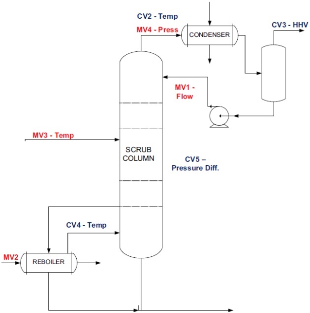
For the scrub column and the deethanizer, the main manipulated variables (MV) are the reboiler steam flow and the reflux flow rate. In addition, the operating pressure is used as an MV to add further flexibility for optimization. The main controlled variables are the product properties and the column differential pressure (to prevent column flooding). The operating temperatures are also maintained within constraints. The HHV of LNG is also included to control this in a tight range, so as to minimize giveaway of heavier components.
Since the properties are important variables in the controller, inferential properties for the column overhead and LNG HHV are developed. The HHV of the scrub column overhead is a function of column top PCT (Pressure Compensated Temperature). The LNG HHV can be calculated as a function of the scrub column overhead HHV and reinjected C2, C3, and C4. These inferential property estimators are used along with the analyzers (bias update) to obtain frequent, reliable measurements for APC. Similarly, inferential measurements are developed and used for deethanizer top and bottom quality variables.
The design of the liquefaction section APC is developed to achieve the key economic objectives. The manipulated and controlled variables selected for this purpose are listed in Table 2 and shown in Figure 13. The main economic objective here is to maximize the LNG production by pushing against the capacity limiting constraints. The constraints could be compressor power/speed, exchanger temperature approaches, or the flash drum pressures. In addition, load shifting between C3 and MR compressors need to be performed with varying ambient conditions to maximize capacity. If the LNG plant capacity is limited by the market conditions, the efficiency needs to be maximized. These objectives are formulated in the APC controller, which is then used to calculate the steady state targets for the manipulated and control variables.
In the APC design, the compressor speeds, light mixed refrigerant flow (LMR) and heavy mixed refrigerant flow (HMR) are main manipulated variables for the liquefaction section. The makeup flows for the mixed refrigerants (MR) are used as manipulated variables as they add further flexibility for control. The main disturbance variable is the cooling medium temperature, either ambient air or seawater temperature.
The manipulated variables are used to control the LNG temperature and HMR/LMR ratio. In addition, the compressor constraints like pressure ratio and driver constraints like power are included. The valve outputs are also included in the controller to ensure that the valves do not become saturated (mainly LNG off-take valve, HMR flow valve, and LMR flow valve). The key approach temperatures for the MCHE are controlled variables, since these are important for equipment protection (Figure 13).