Liquefied natural gas (LNG) properties, such as its high energy density and low temperature storage requirements, make it an efficient and practical solution for long-distance transportation of natural gas.
Liquefied natural gas is a clear, colorless, non-toxic liquid that forms when natural gas is cooled to around -162 °C (-260 °F) at atmospheric pressure. It is highly energy-dense, occupying around 1/600th of the volume of natural gas in its gaseous state, which makes it more economical to transport over long distances. LNG is primarily composed of methane, with small amounts of ethane, propane, butane, and other trace gases.
Physics and Chemistry
Reference: SIGTTO “LNG Shipping Suggested Competency Standards”, Sections:
1 Have an awareness of the physics relating to the change of state of fluids:
- Latent heat;
- Heat and energy transfer;
- Refrigeration and liqefaction of gases;
- Critical temperatures;
- Diffusion and mixing of gases.
2 Know and understand the “Gas Laws” and how they are applicable to LNG operations: pressure and temperature relationship.
3 Know and understand the physics relating to the change of state of the various components involved in relation to LNG:
- Assuming atmospheric pressure, temperatures at which following components change from vapour to liquid:
- Butane;
- Propane;
- Ethane;
- Methane;
- Nitrogen.
- Behaviour of CO2 relative to other components.
4 Know and understand the principles involved in the changing of tank atmosphere:
- Know the physics involved in the piston purge effect and stratification;
- Know the methods that can be used to change tank atmospheres;
- Know which method should be used and explain why.
5 Have an awareness of the parameters for Inert Gas:
- O2 content;
- CO content;
- CO2 content;
- Dew point.
6 The meaning of “dew point”: know the importance of dew point in cargo operations.
7 Know and understand the principles used during the tank cool down process: know the principles for latent heat.
Latent heat
This is the heat given to or taken from a substance to change its physical state, from solid to liquid (latent heat of fusion) or from liquid to vapour (latent heat of vaporisation), while the temperature remains constant.
Heat and energy transfer
Heat is a form of energy that is capable of transmission through solids or fluids by either:
- Conduction, which involves the transfer of energy from one molecule to adjacent molecules without the substance as a whole moving.
- Convection, which involves the migration of warmer parts of a substance away from the source of heat. This only takes place in liquids and gases.
- Radiation, which is the transfer of heat energy in the form of electromagnetic radiation.
Evaporation
This is the process through which a substance is converted from a liquid state into a vapour.
Condensation
Condensation is an exothermic process, where a substance is converted from a vapour into a liquid state, meaning that it releases heat.
Condensation. When a compressed vapour passes through a condenser, the latent heat released heats up the cooling water and the remaining condensate will be approximately the temperature of the condensing medium (e. g. seawater, freshwater).
Refrigeration and liquefaction of gases
The principles of heat transfer, evaporation and condensation are applied in Cargo Temperature Control and Cargo Vent Systemsrefrigeration systems. Figure 1 shows the operating cycle of a simple shipboard refrigeration cycle on a fully refrigerated LPG carrier. LNG reliquefaction systems are discussed in detail in Section 2.17.
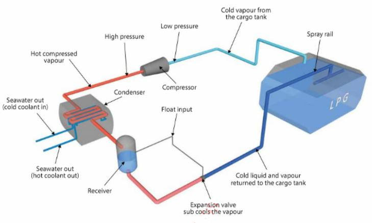
In a single stage compression reliquefaction cycle, the boil-off vapours from the cargo tank are compressed. This compression process increases the pressure and temperature of the vapour, allowing it to be condensed by the cooling medium (usually seawater). The condensed liquid is then returned back to the tank via an expansion valve. The liquid/vapour mixture that is returned to the cargo tank is normally distributed by a spray rail to maximise the cooling effect within the tank.
Critical temperature
This is the highest temperature a gas can reach while still capable of being condensed by the application of pressure. The pressure of a gas at its critical temperature is known as its critical pressure.
Diffusion and mixing of gases
When liquids of differing densities are loaded into the same tank, without any mixing having taken place, there is a possibility of layering.
Generally, for LNG tanks, layering may take place due to:
- The LNG becoming aged or weathered, where the initial composition of the liquid gradually changes over a period of time.
- Genuine density differences (cargoes from different geographical locations may have differing compositions).
- A high concentration of N2 in the feed gas.
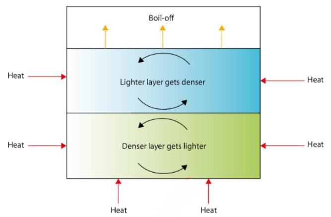
Instability will occur between the layers if the lower layer becomes less dense than the upper, leading to stratification within the tank. This can happen when heat is input to the lower portion while evaporation of methane is taking place in the upper layer, leaving a higher percentage of the heavier ends (weathering).
If a cargo is stored for any length of time and boil-off is removed to maintain tank pressure, evaporation will cause an increase in density and a reduction of temperature near the liquid surface. The static head will create a higher pressure, so at the tank bottom there will be an increase in temperature and a lower density.
This unstable equilibrium will exist until some disturbance occurs, such as the addition of new liquid. Spontaneous mixing will then take place, with a violent production of large quantities of vapours. If “rollover” is anticipated, the tank contents should be circulated or mixed at regular intervals, where possible.
“Rollover” can also occur if the same or compatible cargoes of different densities are put into a tank or if two part-cargoes are loaded into the same tank as there would be a large boil-off caused by any temperature difference between the two.
Where two LNG cargoes of different specific gravity (SG) are mixed, the resulting SG will be somewhere between the two. The resulting SG may be found using a simple ratio calculation.
Gas Laws
It is not only by alteration of its temperature that the volume of a gas can be changed. Changing the pressure exerted on it can also have this effect.
This tells us that a gas has three properties, “volume”, “temperature” and “pressure”, all of which may change. Early investigation of the physical properties of gases showed that, in certain respects (for a fixed number of moles), all the different gases behave in exactly the same way.
Boyle’s Law
The relationship between volume and pressure at constant temperature. Boyle’s Law says that, for a fixed amount of gas at a fixed temperature, the pressure and the volume are inversely proportional.
In other words, as pressure increases, volume decreases.
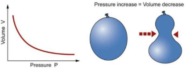
When you squeeze on a balloon to increase the pressure,the volume of the balloon reduces.
Charles’ and Gay-Lussac’s Laws
The relationship between volume and temperature at constant pressure. Charles’ Law says that, for a fixed amount of gas at a fixed pressure, the volume is proportionate to the temperature.
In other words, as the temperature increases, the volume increases.
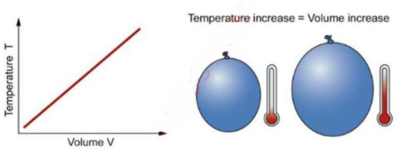
When you heat a balloon the volume of the balloon increases. Gay-Lussac’s Law says that, for a fixed amount of gas at a fixed volume, the pressure is proportionate to the temperature.
In other words, as the temperature increases, the pressure increases.When you squeeze on a balloon to increase the temperature, the volume of the balloon increases.
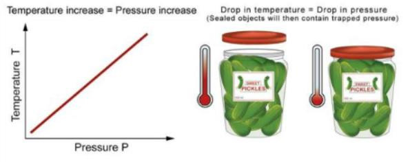
When you put a jar in the refrigerator, the drop in pressure from the trapped air becoming colder makes it hard to open the jar later!
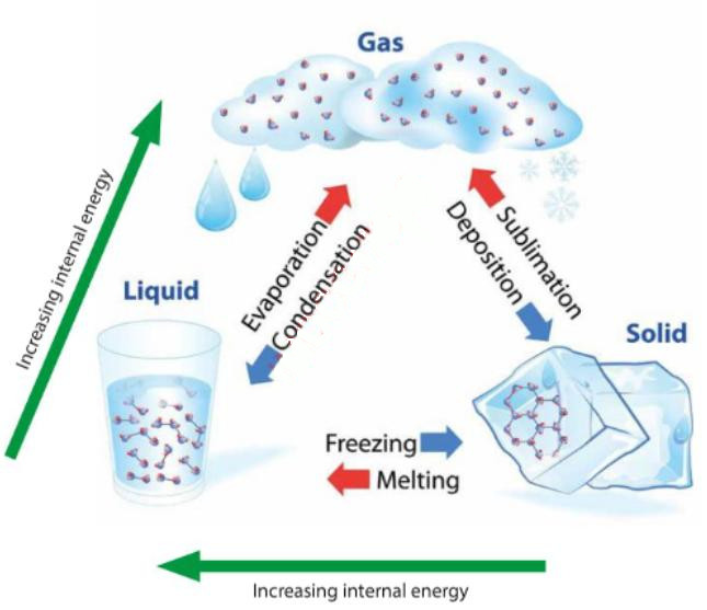
Change of state
Gas, liquid and solid are the three primary states of matter. A solid has a definite shape and volume. A liquid has a definite volume and takes the shape of its container. A gas fills the entire volume of a container.
Most substances can exist in either a solid, liquid or vapour state. There are specific terms used for each of the changes from one state of matter to another:
1 Energy
This is involved in each of the various changes of state that occur, primarily in the form of heat. Each of the changes of state processes either uses heat or releases heat.
2 Latent heat
When a substance changes from the solid phase to the liquid phase, energy must be supplied in order to overcome the molecular attractions between the constituent particles of the solid. This energy must be supplied externally, normally as heat, but does not bring about a change in temperature. We call this energy “latent heat”.
The two latent heats are typically described as the latent heat of fusion (melting), and the latent heat of vaporisation (evaporation).
3 Heat of fusion
This is the amount of thermal energy that must be absorbed or lost for 1 gram of a substance to change state from a solid to a liquid, or vice versa. It is also called the latent heat of fusion (or the enthalpy of fusion) and the temperature at which it occurs is called the “melting point”. When you withdraw thermal energy from a liquid or solid the temperature falls. When you add thermal energy to a liquid or solid the temperature rises. At the transition point between solid and liquid (the melting point), extra energy is required (the heat of fusion). To go from liquid to solid, the molecules of a substance must become more ordered. For them to maintain the order of a solid, extra heat must be withdrawn. In the other direction, to create the disorder from the solid state to liquid, extra heat must be added.
The heat of fusion can be observed if you measure the temperature of water as it freezes. If you plunge a closed container of water at room temperature into a very cold environment (say minus 20 °C (-20 °C)), you will see the temperature steadily fall until it drops just below the freezing point (0 °C). The temperature then rebounds and holds steady while the water crystallises. Once completely frozen, the temperature will fall steadily again.
4 Latent heat of vaporisation
A change of state from liquid to vapour at constant temperature also requires the input of energy, called the “latent heat of vaporisation” (or standard enthalpy change of vaporisation). This implies that while a liquid undergoes a change to the vapour state at the normal boiling point, the temperature of the liquid will not rise beyond the temperature of the boiling point. The latent heat of evaporation is the energy required to overcome the molecular forces of attraction between the particles of a liquid, which brings them to the vapour state where such attractions are minimal.
When a liquid evaporates, it cools. This is because it is the higher energy molecules that leave the surface of the liquid, leaving lower energy molecules behind in the body of the liquid.
Changing from a gas to a liquid
Gas can be moved using pipelines, although for transportation over long distances it becomes more economic to move it by ship. To transport a gas over a long distance it must first be liquefied as the liquefaction process reduces natural gas to 600 times less than its volume in the vapour state.
When a gas is compressed its molecules are forced closer together and, as their vibratory motion area is reduced, heat is given off. As compression proceeds the speed of the molecules and the distances between them continues to decrease until, eventually, the substance undergoes a change of state and becomes liquid. Due to this effect, extreme cooling is not necessary during the liquefaction of gases. However, some level of cooling is required as each gas has a definite temperature, called its “critical temperature”, above which it cannot be liquefied regardless of the pressure exerted upon it.
A gas must be cooled to below its critical temperature before it can be liquefied. As an example, to convert natural gas to a liquid it must be cooled to the temperature at which the main component, methane, will form a liquid. This is approximately minus 161,5 °C (-161,5 °C) or minus 256 °F (-256 °F).
The liquefaction process works in a similar manner to a typical refrigerator. Cold liquid refrigerants, such as propane and ethylene, are reduced in pressure and evaporated as heat is exchanged with the natural gas steam. As this happens, it cools the natural gas to the point where it turns into a liquid. Once the gas has been liquefied, it is sent to storage (in dedicated, specially constructed tanks) to await shipping.
Gases and vapours
As this is now a liquefied product, during shipping the behaviour of the substance as a vapour, rather than as a gas, must be considered. An important distinction between gases and vapours is that a gas is a substance in its gaseous state at a temperature above its critical temperature that cannot be liquefied by compression alone. However, a vapour is a substance on its gaseous state at a temperature that is below its critical temperature. For a vapour, the critical pressure is the pressure required to compress a vapour to liquid at its critical temperature.
Saturated vapour pressure
The average energy of the particles in a liquid is governed by their temperature. The higher the temperature, the higher the average energy. However, within that average, some particles have energies higher than the average and others have energies that are lower.
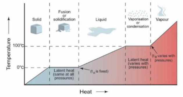
A – rise in temperature as ice absorbs heat;
B – absorption of latent heat of fusion;
C – rise in temperature as liquid water absorbs heat;
D – water boils and absorbs latent heat of vaporisation;
E – steam absorbs heat and thus increases its temperature
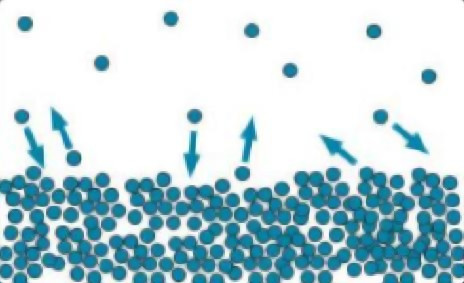
Some of the more energetic particles on the surface of the liquid can be moving fast enough to escape from the forces of attraction holding the liquid together. This means they will evaporate.
Note that evaporation only takes place on the surface of the liquid. This is different from boiling, which happens when there is enough energy to disrupt the forces of attraction throughout the liquid. It is the reason why, if you look at boiling water, you will see bubbles of gas being formed all the way through the liquid.
If you look at water that is evaporating in the sun, you don’t see any bubbles. Water molecules are simply breaking away from the surface layer. Eventually, the water will all evaporate in this way. The energy lost as the particles evaporate is replaced from the surroundings. As the molecules in the water jostle with each other, new molecules will gain enough energy to escape from the surface.
The evaporation of a liquid in a closed container
Now imagine what happens if the liquid is in a closed container. Water in a sealed bottle does not seem to evaporate and, or at least, it doesn’t disappear over time.
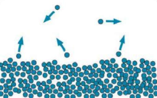
However, there is constant evaporation from the surface as particles continue to break away from the surface of the liquid and are trapped in the space above the liquid.
As the gaseous particles bounce around, some of them will hit the surface of the liquid again and be trapped there. An equilibrium will rapidly be established in which the number of particles leaving the surface is exactly balanced by the number rejoining it.
In this equilibrium, there will be a fixed number of gaseous particles in the space above the liquid.
When these particles hit the walls of the container, they exert a pressure. This pressure is called the “saturated vapour pressure” (also known as “saturation vapour pressure”) of the liquid.
A high vapour pressure means that the liquid must be volatile. Molecules escape from its surface relatively easily, resulting in larger numbers of them in the gaseous state once equilibrium is reached.
| Temperatures (boiling points) at which various gases change state at atmospheric pressure | |
|---|---|
| Butane | minus 0,5 °C (-0,5 °C) |
| Propane | minus 42,8 °C (-42,8 °C) |
| Ethane | minus 88,6 °C (-88,6 °C) |
| Methane | minus 161,5 °C (-161,5 °C) |
| Nitrogen | minus 195,9 °C (-195,9 °C) |
If you increase the temperature, you are increasing the average energy of the particles present. This means that more of them are likely to have enough energy to escape from the surface of the liquid, which will tend to increase the saturated vapour pressure.
| Typical LNG Compositions (% mol) | ||||||
|---|---|---|---|---|---|---|
| CH4 (Methane) | C2H6 (Ethane) | C3H8 (Propane) | C4H10 (Butane) | C5H12 (Pentane) | N2 (Nitrogen) | |
| Arzew (Algeria) | 87,1 | 8,6 | 2,1 | 0,05 | 0,02 | 0,35 |
| Bintulu (Malaysia) | 91,23 | 1,3 | 2,95 | 1,1 | 0 | 0,12 |
| Bonny (Nigeria) | 90,1 | 5,2 | 2,8 | 1,5 | 0,02 | 0,07 |
| Das Island (UAE) | 81,53 | 13,39 | 1,31 | 0,28 | 0 | 0,17 |
| Arun (Indonesia) | 89,33 | 7,14 | 2,22 | 1,17 | 0,01 | 0,08 |
| Kenai (Alaska) | 99,8 | 0,1 | 0 | 0,1 | 0 | 0,1 |
| Lumut (Brunei) | 89,4 | 6,3 | 2,8 | 1,3 | 0,05 | 0,05 |
| Marsa El Brega (Libya) | 70 | 15 | 10 | 3,5 | 0,6 | 0,9 |
| Point Fortin (Trinidad) | 96,2 | 3,26 | 0,42 | 0,07 | 0,01 | 0,008 |
| Ras Laffan (Qatar) | 90,1 | 6,17 | 2,27 | 0,6 | 0,03 | 0,25 |
| Skikda (Algeria) | 91,5 | 5,61 | 1,5 | 0,5 | 0,01 | 0,85 |
| Withnell (Australia) | 89,02 | 7,33 | 2,56 | 1,03 | 0 | 0,06 |
Behaviour of CO2 relative to other components/issues with CO2
The main constituents of inert gas are carbon dioxide (CO2) and nitrogen (N2). On an LNGC, if inerting of cargo tanks is to be carried out using ship generated IG, a gassing-up operation will also be necessary as CO2 will freeze at temperatures below minus 56,6 °C (-56,6 °C) and so will contaminate the cargo if brought in direct contact with LNG (at minus 161,5 °C (-161,5 °C)). Solid CO2 can create operational difficulties as it can block or damage valves and pumps. More commonly, CO2 produces a white powder that can block filters and nozzles.
Carbon Dioxide is a risk if it is in contact with LNG as it freezes at minus 56,6 °C (-56,6 °C).
The “piston effect” and stratification
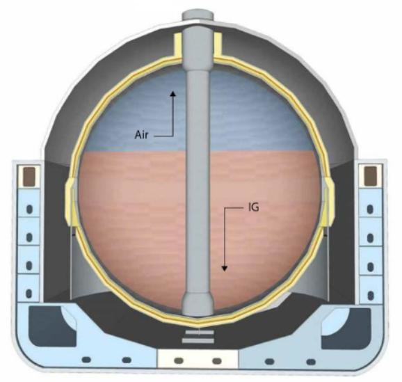
The “piston effect” is the most efficient means to completely displace a tank’s atmosphere. The existing atmosphere is expel led, as if by a plunger in a syringe.
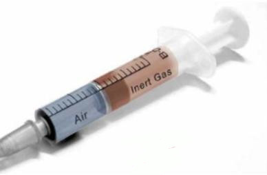
Inerting by displacement relies on the stratification (interface) in the cargo tanks that is a result of the difference in vapour density between the gas entering the cargo tanks and the gas already within them.
Methods to change tank atmospheres
If perfect stratification (interface) was achieved with no mixing at the interface, then one tank volume of the incoming IG would completely displace the tank atmosphere. However, in practice, mixing does occur and so it is necessary to use more than one tank volume of IG (usually 1,7 to 2 tank volumes). With primary inerting, there is little density difference between air and IG (IG is slightly heavier). This makes inerting solely by displacement difficult to achieve and the process will become part displacement and part dilution. In the case of primary inerting, the IG can be taken through the liquid loading line to the bottom of the tank, with the air/IG removed via the vapour line and into the vent header.
Read also: Cargo Containment Systems of LPG and LNG
In the dilution method, the incoming gas mixes with the gas already in the tank and the O2 content reduces with each tank volume that passes through. This allows for a thorough atmosphere change and ensures there is a lower chance of pockets of the existing tank atmosphere remaining. However, the dilution method takes longer than the displacement (piston effect) method.
While the dilution method is longer, it is more thorough, and though some operators may start by displacement (in the belief that they will be speeding up the operation) they will generally finish with a period of dilution to ensure that all pockets are reached. If the “piston effect” is used while gas freeing or purging, the pressure in the tanks must be kept low to maximise the effect.
“Dilution” is the free mixing of the incoming gas with the gas already in the tank.
Inert Gas (IG)
IG is used on LNGCs to prevent combustion of flammable vapours. Inerting refers to the process of replacement of air and flammable vapours with that of IG to create an atmosphere insufficient for combustion.
| Item | IG |
|---|---|
| Nitrogen | 85-89 % |
| Carbon dioxide (CO2) | 14 % |
| Carbon monoxide (CO) | 0,1 % |
| Oxygen (O) | 1-3 % |
| Sulphur oxides | 0,1 % |
| Dewpoint | minus 45 °C (-45 °C) |
| Density (where air = 1,00) | 1,035 |
IG is usually produced on board in an IG plant/system, although it may also be provided from ashore. The typical composition of IG produced on board is as follows:
Dew Point
Due to the cryogenic temperatures involved in LNG operations, any moisture in the cargo system would freeze, creating significant operational difficulties, and possible equipment damage and cargo contamination, with resultant commercial and operational impact.
The dryness of a vapour or gas can be determined by the measurement of its dew point. Although dew point is referred to as a temperature, this does not refer to the physical temperature of the gas or vapour. It is the temperature at which the first drop of liquid would appear.
Note: the lower the dew point, the less moisture in the vapour or gas.
Cooldown
Cooldown is the process that brings the cargo containment system to a temperature that does not cause excessive boil-off during loading and prevents thermal shock to the primary containment system.
The cooldown operation is achieved by introducing LNG through the spray header and cooldown grids at the top of each tank. The LNG will vaporise at the spray nozzle and cold LNG vapour will enter the tanks.

On membrane ships cooldown is continued until minus 130 °C (-130 °C) is achieved at the average tank temperatures (excluding top sensor).
An example of how long cooldown takes: 140 000 m3 membrane approximately 10 hours from +40 °C to minus 130 °C (-130 °C), where the ship is now ready to load.

On Moss type ships, cooldown is continued until minus 115 °C (-115 °C) is achieved at the equatorial ring.
An example of how long cooldown takes: 135 000 m3 Moss system approximately 24 hours from +40 °C to minus 115 °C (-115 °C), where the ship is now ready to load.
Principles for heat transfer
“Heat” has the same relationship to thermal energy that “work” has to mechanical energy. Heat flows between regions that are not in thermal equilibrium and, in particular, it flows from areas of high temperature to areas of low temperature. During loading or discharging, heat will transfer from the surrounding atmosphere via the pipelines through which the LNG passes, regardless of the extent to which they are insulated.
Heat transfer includes latent heat. This is defined as the transfer of heat through a physical change in the medium, such as water to ice or water to steam. This involves significant energy and is exploited in many ways, such as in the steam engine, a refrigerator, etc.
The quantity of heat necessary to raise the temperature of a substance depends on its nature, mass and the required increase in temperature. Units of heat are based on water and the two most commonly units used are:
1 The British thermal unit (Btu)
The quantity of heat required to raise the temperature of 1 lb of water through 1 °F.
2 The Kilo calorie (k/cal)
The quantity of heat required to raise the temperature of 1 kg of water through 1 °C.
Heat Transfer
Within the LNG industry, heat transfer effects are demonstrated in the following ways:
- When LNG is in an insulated pipe, the inside surface of the pipe is at the undercooled temperature of the fluid, approximately minus 161,5 °C (-161,6 °C), and with the outer fabric of the insulation at ambient temperature, establishing a thermal gradient. As the condition of the insulation deteriorates, the heat ingress into the fluid increases and, in severe cases, an undesirable “cold path” forms.
- The insulation of vapour lines is also important, particularly on the suction side of the gas compressors, which handles volumetric flow. Density increases proportionally the colder the fluid and with increased density comes increased calorific value per unit volume handled by the compressors.
- Heat transfer is also an important consideration when carrying out inner hull inspections (IHI). As with pipeline insulation, when cargo tank insulation deteriorates a cold spot (icing) may form on the steel work of the inner hull.
Many essential processes In the LNG trade, such as tank/line cooldown and pre-refit warm-up, depend on these principles.
During the cooldown process, particularly on membrane systems, a significant pressure reduction occurs in the N2 pressurised primary space due to volumetric contraction of the pressurising medium. The collapse in pressure can, on occasions, be dramatic if not counteracted in time, so it is essential to maintain the primary and secondary space pressures at the prescribed level (typically 2-4 mbar).
When considering the process of heat transfer, you should think of the materials involved and the effect of heat or cold on their molecular structure.
Principles for latent heat
This is the heat given to or taken from a substance to change its physical state from solid to liquid (latent heat of fusion) or from liquid to vapour (latent heat of vaporisation) while the temperature remains constant.
The values of latent heat are expressed in heat units per unit weight. In the case of changing the state of a substance from a solid into a liquid (melting), it is called the latent heat of fusion. In the case of changing the state of a liquid into a vapour (boiling), it is called the latent heat of vaporisation. The latent heat of ice is 80 kcal/kg, so if ice is at its melting point of 0 °C it would need to be given 80 kcal for every kg weight to melt it into water at the same temperature or, if water is at its freezing point of 0 °C, 80 kcal would need to be extracted from each kg to freeze it into ice at the same temperature.
The large increase in volume at the liquid to vapour phase change means that trapping LNG between valves for any length of time poses a considerable pressure hazard and requires systems to prevent such dangerous over-pressurisation. Unlike the shore installation, a reverse change of state in LNG from vapour to liquid will only become an issue when Gas Tanker Equipment and Instrumentationonboard reliquefaction is fitted and becomes an integral part of a ship’s containment system (e. g. safety relief valves must be fitted in any section of line or equipment that can be isolated).
Latent Heat
The relevance of the principles of latent heat to the LNG industry are as follows:
- Although the temperature remains constant during a phase change, the volume does not. When LNG vaporises, the volume typically increases by 600 times. Therefore, during the cooldown process, when liquid is sprayed into a cargo tank and vaporises, the vapour generated has the potential to significantly increase the cargo tank pressure. This means there is a need to have effective systems in place to counteract this potentially massive pressure increase.
- During the pre refit warm-up process the residual LNG must be vaporised by hot gas circulation. Again, during the latent heat of vaporisation stage, the potential increase in tank pressure is significant.
- As well as understanding the latent heat process, it is necessary to remember that LNG is a mixture of different components in varying amounts. This means that the constituent parts will undergo the latent heat of vaporisation effect at different stages and times during the voyage, i. e. the light ends will vaporise first, increasing the percentage of heavier ends in the remaining liquid.
Principles of Design
Reference: SIGTTO “LNG Shipping Suggested Competency Standards”, Sections:
1 Have an awareness of the main design principles: be aware of the principles for protection of cargo containment systems.
2 Know and understand the main design principles: know and understand the principles for protection of cargo containment system.
Principles for protection of cargo containment systems
LNGCs are designed to survive the normal effects of flooding following the expected hull damage/breach from incidents such as grounding, collision or stranding. The cargo tanks are protected from flooding by positioning them at specified minimum distances inboard from the ship’s hull.
The construction guidelines for LNGCs are found in “The International Code for the Construction and Equipment of Ships Carrying Liquefied Gases in Bulk” commonly known as the IGC Code, which details the following main design principles for liquefied gas carriers:
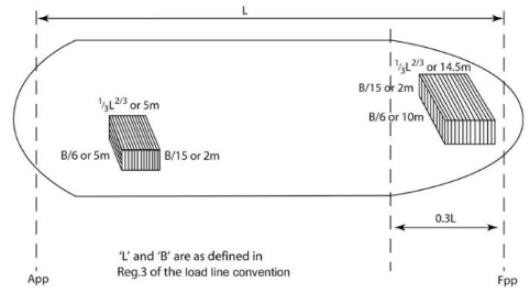
1 Damage assumptions: the maximum assumed extent of damage is:
| Longitudinal extent | 1/3 Length 2/3 or 14,5 m, whichever is less |
| Transverse extent | Breadth/6 or 10 m, whichever is less |
| Vertical extent | Breadth/15 or 2 m, whichever is less |
2 Secondary Barrier
The secondary barrier is to act as a temporary containment for any envisaged leakage of LNG from the primary barrier. It is designed to contain any leakage for a period of at least 15 days.
3 Insulation
Suitable insulation should be provided to ensure that the temperature of the hull structure does not fall below the minimum allowable design temperature for the grade of steel concerned.
4 Cargo tank vent systems
Cargo tanks should be provided with a pressure relief system appropriate to the design of the cargo containment system and the cargo being carried.
Note: this relief system for the cargo tanks protects against over-pressurisation and vacuum.
Hold spaces,interbarrier spaces and cargo piping, which may be subject to pressures beyond their design capabilities, should also be provided with a suitable pressure relief system.
All LNGCs have double hulls throughout their cargo length. These provide adequate space for ballast. Interbarrier spaces around the cargo tanks are continuously inerted, except in the case of spherical Type B containment systems, where the hold spaces may instead be filled with dry air provided that there is an adequate means for inerting such spaces in the event of cargo leakage. Continuous gas monitoring of all hold spaces is mandatory.
Note: when monitoring gas In the annular space or interbarrier/insulation spaces, use % volume scale as you are sampling gas in an inert atmosphere.
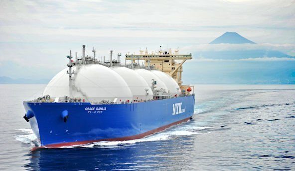
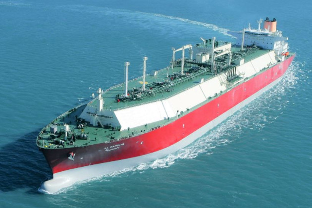
The containment systems on the world fleet of LNGCs are, predominantly, of two main types:
- Moss Type B (spherical) type – with a partial secondary barrier.
- Membrane type – with a complete secondary barrier. The most common designs are GTT N096 and Mark III.
While the Type B Moss and membrane types are discussed here, there are several other containment designs that are not widely utilised. For more detailed information on all types of tank construction, see Section 2.1.
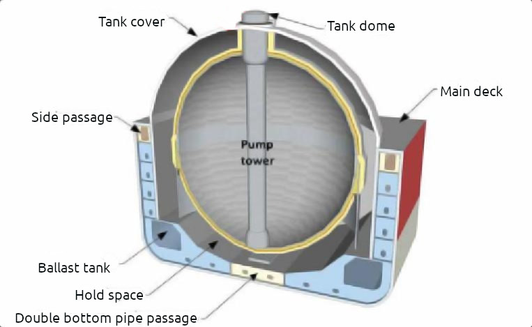
Moss Type B Tank
General overview: type B tanks are generally spheres.
Construction. The containment system is subjected to a thorough stress analysis and must include fatigue life and crack propagation analysis. Because of these design factors, the Type B tank requires only a partial secondary barrier, comprising a drip tray and a splash barrier. When carrying flammable cargoes, the hold space in this design is filled with either IG or dry air. When dry air is used, the hold space must be capable of being inerted.
A protective steel dome (weather cover) covers the primary barrier above deck level and insulation is applied to the outside of the primary barrier surface. Although the spherical Type B tank was originally designed for LNG carriage, it can also be used for LPG carriers, primarily those carrying ethylene.
Insulation. The cargo tank is a self-supporting, predominantly aluminium sphere that is carried by a cylindrical skirt at the equator. The containment system is based on the principle of “leak before fail”.
The insulation system consists of two layers:
- Layer 1 – phenolic resin foam.
- Layer 2 – polyurethane foam.
The insulating structure is reinforced by wire nets and covered with an AL-PET aluminium foil sheet. The insulation also doubles as a spray shield.
Any leaked cargo drains by gravity through the annular space, between the cargo tank and the insulation, to the bottom of the sphere. An opening in the insulation leads to a rupture disc that opens under cryogenic temperatures, allowing the liquid to drain into the drip-pan in the cargo hold space beneath.
Cargo tank vent systems. The IGC Code for Gas Carriers requires at least two pressure relief valves of equal capacity to be fitted to any cargo tank with a volume greater than 20 m3. On tanks with a volume less than 20 m3, one pressure valve is considered to be sufficient.
The types of valves normally fitted are either spring loaded or pilot operated relief valves (PORV). PORVs are commonly used on cargo tanks. Spring-loaded relief valves are generally used on cargo pipework and equipment.
Although the Moss spherical Type B tank can operate at the slightly higher pressure of 1,9 barG (emergency discharge),the normal relief valve set pressure for both Type A and Type B tanks is 0,25 barG.
Pressure relief valve design must take account of at least two basic requirements:
- Over-pressurisation.
- Overheating of the tank contents.
The Classification Societies have defined rules that determine the amount of gas to be discharged as a function of the liquid volume in the tank, the dimensions of the tank and the amount/effectiveness of the thermal insulation of the tank.
The rules also create a requirement for high gas flow rates.
Pressure relief valves are, therefore, principally designed to satisfy the following requirements:
- To provide an effective seal until the pre-set opening pressure (set pressure) is reached;
- Achievement of a precise and clean release of gas, regardless of cargo temperature;
- Complete opening of the valve to give full flow;
- Complete closing of the valves at a pressure slightly below the opening pressure;
- The operation has to be free from the effects of frosting that may occur within the valve;
- The operation has to be unaffected by acceleration due to movement in a seaway,by list or by trim;
- The valve must consistently open at the prescribed set pressure;
- Pressure relief valves should be type tested to ensure that the valves have the capacity required;
- Pressure relief valves should be set and sealed by a competent authority acceptable to the flag State and a record of this action, including the values of set pressure,should be retained aboard the ship;
- Back pressure in the vent pipe system should not impede full flow of the valve.
Such a leak might be caused by a crack in a weld.The containment system is fitted with a gas and leak detection system.
Any cargo flow from a leak would flow between the tank and the insulation and be collected in the drip pan in the hold space, which is insulated with polystyrene and a stainless steel layer. Gas and liquid monitoring alarms would quickly and accurately detect the presence of cargo.
Any liquid leakage from the northern hemisphere of the tank will be collected at the upper ring of the stiffening skirt and led to one of 4 drain pipes, fore, aft, port or starboard,and then led to the drip pan. In the southern hemisphere of the tank it will be led to a drainpipe at the south pole and then routed to the drip pan.
Prior to liquid entering the drip pan, it will pass through a rupture disc (bursting disc), designed to fail at cryogenic temperatures.
The temperature sensor in the drip pan will indicate whether it is a cryogenic temperature, a liquid LNG leakage,or above 0 °C, indicating that it is water.
An eductor system is fitted to the drip pan.
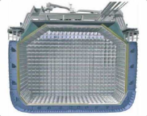
Membrane containment system
The membrane cargo containment system is based on a very thin primary barrier, or membrane, that is supported by a layer of insulation within the confines of the hull of the ship.
The membrane system differs from the self-supporting tanks in that the membrane containment system must be provided with a complete secondary barrier to ensure cargo integrity in the event of leakage of the primary barrier. There are two principal types of membrane system, designed by GTT, that are in common use (Mark III and N096).
Before 2005, the maximum size of LNGC was about 135 000 m3, and the shipowner would choose either a membrane or Moss Type B spherical construction. However, the advent of far larger LNGCs has seen the membrane design dominate as it makes better use of the internal hull space.
GTT NO96 membrane system. In the N096 system, the primary and secondary membranes are identical, providing 100 % redundancy. The primary and secondary layers are constructed of the same materials i. e., they comprise of a 0,7 mm thick invar skin and a 200 mm layer of perlite filled plywood boxes that act as insulation.
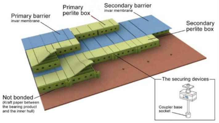
Insulation Layers
At the design stage, the thickness of the insulation layers is adjusted to achieve the desired cargo boil-off rates for fuelling the boilers, propulsion systems and auxilliaries.
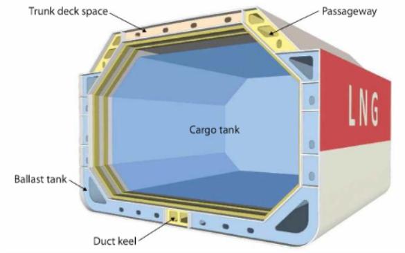
GTT Mark III membrane system. In the GTT Mark III membrane system, the primary barrier is stainless steel constructed of “cross corrugations”, or “waffles”, that allow for any expansion or contraction.
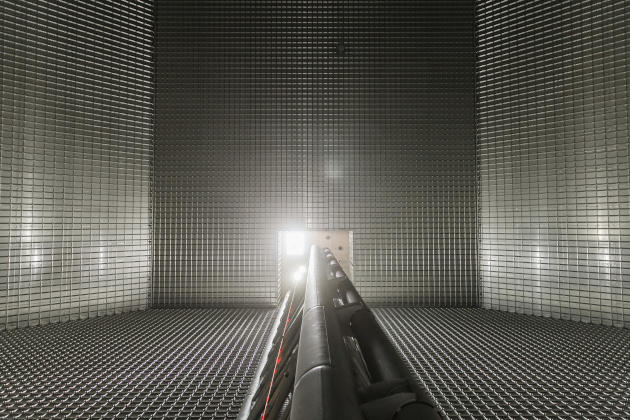
The primary barrier is supported by an insulation layer constructed of reinforced cellular foam. In between the insulation layers is a cloth made of laminated fibreglass and aluminium that acts as the secondary barrier (i. e. triplex cloth). This secondary barrier is able to contain LNG leakage for 15 days.
Other types of containment system
There are other types of containment system but, to date, construction is very limited. For example, other types include the “CS1” system, the “LNT A-box” system and the “SPB” system. For more detailed information on tank construction, see Section 2.1.