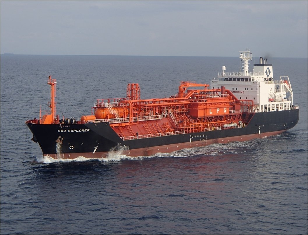
This article maintain massive information about gas tanker equipment, like pipes, valves, compressors, heaters etc.
- Tanks, piping and valves
- Cargo valves
- Pressure-relief and vacuum protection system
- Pumps and unloading system
- Pump performance curves
- Running pumps in parallel and in series
- Deepwell pumps
- Submerged pumps
- Booster pumps
- Methanol injection to cargo pumps
- Cargo heaters and cargo vaporizers
- Heat exchanger
- Tube heat exchangers
- Plate heat exchangers
- Reliquefaction systems and control of boil-off
- Cargo compressors
- Piston compressors
- Double-acting compressors
- Single-acting compressors
- Screw compressors
- Oil free screw compressors
- Compressor suction liquid separator
- Purge gas condenser
- LNG boil-off and vapour handling systems
- Inert gas system
- Inert gas generators
- Combustion chamber
- The refrigerated drier
- The absorption drier
- Nitrogen production on ships
- Pure nitrogen from the shore
- Instrumentation
- Intrinsically safe (i.s.) equipment
- Flameproof equipment
- Pressurised or purged equipment
- Liquid level
- Float gauges
- Nitrogen bubbler gauges
- Differential pressure gauges
- Capacitance gauges
- Radar gauges
- Level alarm and automatic shutdown systems
- Pressure and temperature monitoring
- Gas detection systems
Tanks, piping and valves
The loading lines and pipes mentioned here refer to gas carrier’s cargo handling system. This involves:
- liquid lines;
- vapour lines;
- condensate return lines;
- lines to vent mast;
- pipes inside the cargo tank;
- seawater pipes to the cargo cooling plant.
All loading lines on gas carrier: liquid lines, gas lines and lines to vent mast have the same requirements as pressure vessels regarding of temperature and pressure they are meant to handle. All welding on pipes exceeding 75 mm in diameter and 10 mm wall thickness or more must be X-rayed and classed by the class company.
The same regulation do we have on flanges and spool pieces also. All loading lines outside the cargo tank must be produced by material with melting point no less than 925 °C. The loading lines on gas carriers are mostly produced of stainless steel, but low temperature nickel steel is also in use. All loading lines with an outside diameter of 25 mm or more must be flanged or welded. Otherwise, lines with an outside diameter less than 25 mm can be connected with treads.
Loading lines designed for cargo with low temperature, less than -10 °C must be insulated from the ship hull. This to prevent the ship hull to be cooled down to below design temperature. The hull has to be protected against cold cargo spill under spool pieces and valves on all liquid lines. This is done with wood planks or plywood. To prevent cold cargo spill on the hull plates, a drip tray must be placed under the manifold flanges. All lines that are thermally insulated from the hull must be electrically bonded to the hull with steel wire or steel bands. On each flange on lines and pipes where gaskets are used, there must be electrical bonding with steel wire or steel band from flange to flange.
On all cargo lines where it can be liquid it is required with safety valve. Vapour from the safety valve outlet must go back to the cargo tank or to the vent mast. If the return goes to vent mast the pipe must be equipped with a liquid collector to prevent liquid to the vent mast. The safety valve’s set point is dependent upon the pressure for which the line is designed. The safety valves must be tested and sealed by the ship Class Company.
No cargo pipework is allowed beneath deck level on gas carriers; therefore, all pipework connections to tanks beneath deck level must be taken through the cargo tank domes, which penetrate the deck. Vapour relief valves are also fitted on the tank domes; these relieve to vent stacks whose height and safe distances from accommodation spaces etc. are specified in the IMO Codes.
Cargo valves
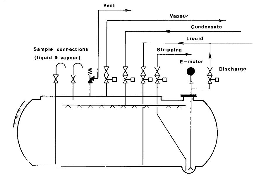
Isolating valves for gas carriers must be provided in accordance with the IMO requirements. Where cargo tanks have a MARVS greater than 0,7 barg (Type C cargo tanks), all main and liquid vapour connections (except relief valve connections) should normally be fitted with a double valve arrangement comprising a manually operated globe valve with a remotely operated isolation valve in series with this manual valve.
For Types A and B cargo tanks with the MARVS less than 0,7 barg the IMO Codes allow shut-off valves for liquid and vapour connections which can be remotely actuated but which must also be capable of local manual operation. Remotely operated emergency shutdown valves are provided at the liquid and vapour crossovers for all gas carriers. Picture 1 shows the cargo tank dome piping and valving arrangement for a typical semi-refrigerated vessel. At several locations around the ship, e.g. bridge front, gangway, compressor room and cargo control room, emergency control stations, pneumatic vent valves or electric push buttons are provided which, when operated, close remotely actuated valves and stop cargo pumps and compressors where appropriate – effectively creating a “dead ship” as far as cargo-handling is concerned.
Emergency shut down (ESD) is also required to be automatic upon loss of electric or control power, valve actuator power or fire at tank domes or manifold where fusible elements are suitably situated to actuate the ESD signal system. Individual tank filling valves are required to be automatically closed upon the actuation of an overfill sensor in the tank to which they are connected. ESD valves may be either pneumatically or hydraulically operated but in either case must be “fail safe“, i.e. close automatically upon loss of actuating power. The possibility of surge pressure generation when the ship’s ESD system is actuated during loading is a vital consideration. The situation varies from terminal to terminal and is a function of the loading rate, the length of the pipeline at the terminal, the rate of closure of the valve and the valve characteristic itself.
The phenomenon of surge pressure generation is complex and its effects can be extreme, such as the rupture of hoses or hard arm joints. Precautions may therefore be necessary to avoid the possibility of damage. Terminals may need to check ships ESD valve closure rates and adjust loading rates accordingly or place on board a means whereby the ship may actuate the terminal ESD system and so halt the flow of cargo before the ship’s ESD valves start to close.
NOTE: Consultation between the ship and shore must always take place in order to establish the parameters relevant to surge pressure generation and to agree upon a safe loading rate.
The types of isolation valve normally found on gas tankers are:
- ball;
- globe;
- gate or butterfly valves.
These valves are usually fitted with pneumatic or, occasionally, hydraulic actuators. Ball valves for LNG and Ethylene service are provided with some means of internal pressure relief; usually, a hole is drilled between the ball cavity and downstream side of the valve. Valves must be of the fire safe type.
Strainers are normally provided at the manifold connections for loading/discharging. It is important not to bypass these strainers and to ensure they are frequently checked and cleaned. The strainers are installed to protect cargo handling plant and equipment from damage by foreign objects. Many strainers are designed for one-way flow only.
Pressure-relief and vacuum protection system
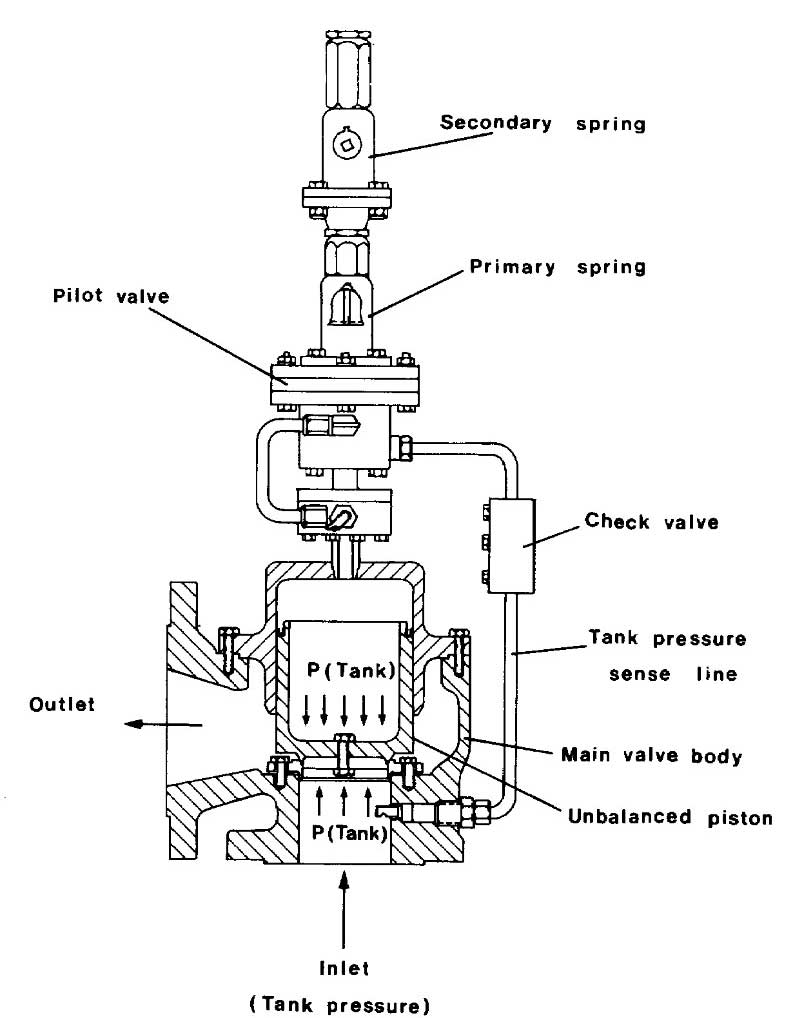
The IMO Codes require at least two pressure relief valves of equal capacity to be fitted to any cargo tank of greater than 20 m3 capacity. Below this capacity one is sufficient. The types of valves normally fitted are either spring-loaded or pilot-operated relief valves. Pilot-operated relief valves may be found on Types A, B and C tanks while spring-loaded relief valves are usually only used on Type C tanks.
The use of pilot-operated relief valves on Type A tanks ensures accurate operation at the low pressure conditions prevailing while their use on Type C tanks, for example, allows variable relief settings to be achieved using the same valve. Changing the pilot spring may do this. Picure 2 shows a typical pilot-operated relief valve of this type. Other types of pilot valve are available for adjustment of “set pressure” and “blow down pressure”.
Adjustable setting of pilot operated relief valves, where provided, are used mainly in two different roles. Firstly, they may be used to provide a higher set pressure (but not exceeding the MARVS) than normal during cargo handling (‘harbour” setting). Secondly, on Type C tanks, they permit an acceptable means of reducing the MARVS to comply with USCG regulations, which impose more stringent safety factors in pressure tank design than do the IMO Code requirements.
Whenever such valves are used for more than one pressure setting a proper record must be kept of any changes in the pilot valve springs, the pilot assembly cap always being resealed after such changes. Cargo tank relief valves relieve into one or more vent stacks. Vent stack drains should be provided, and regularly checked, to ensure no accumulation of rainwater, etc., in the stack. Accumulation of liquid has the effect of altering the relief valve setting due to the resulting increased backpressure.
The IMO Codes require all pipelines or components which may be isolated when full of liquid to be provided with relief valves to allow for thermal expansion of the liquid. These valves can relieve either into the cargo tanks themselves or, alternatively, they may be taken to a vent stack via liquid collecting pots with, in some cases, level switch protection and a liquid vaporising source.
Pumps and unloading system
Cargo pumps fitted aboard refrigerated gas tankers are normally of the centrifugal type, either deepwell or submerged, operating alone or in series with a deck-mounted booster pump where cargo heating is required on discharge to pressurise storage from a refrigerated vessel (see above). Some fully pressurised ships discharge cargo by pressurising tanks and require booster pumps to assist in the transfer of cargo ashore.
Pump performance curves
An understanding of the significance of a pump performance curve is important when considering the work done by cargo pumps. Picture 3 shows typical set of performance curves for a multi-stage deepwell pump.
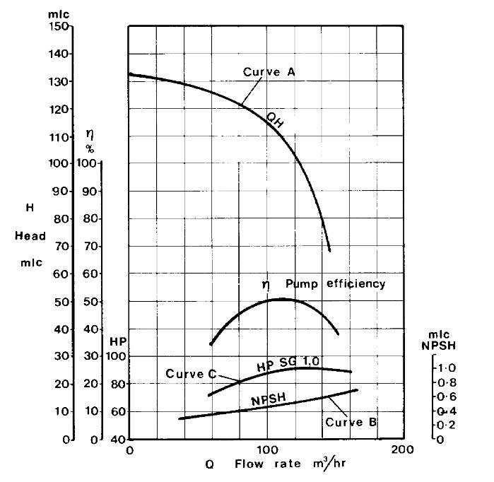
Curve A
Curve A shows the capacity, given in terms of volumetric flow rate (normally m3/hr), of the pump as a function of the head developed by the pump, given in terms of metres liquid column (mlc). Adopting these parameters, the capacity/head curve is the same irrespective of the fluid being pumped. Taking the capacity curve shown in Picture 3, the pump will deliver 100 m3/hr with a head of 115 mlc across the pump. To convert this head into a differential pressure reading the specific gravity of the cargo being pumped must be known.
For example, at a head of 105 mlc the differential pressure across the pump when pumping ammonia at –33 °C with a specific gravity of 0.68 would be:
Note: the factor 10,2 in the foregoing equation denotes the height, in metres, of a water column maintained solely by atmospheric pressure.
Curve B
Curve B shows the Net Positive Suction Head (NPSH) requirement for the pump in question as a function of pump capacity. The NPSH requirement at any flow rate through the pump is the positive head of fluid required at the pump suction over and above the cargo SVP to prevent cavitation at the pump impeller.
For example, at a capacity of 100 m3/hr for the pump performance shown in Figure 3 the NPSH requirement for the pump is 0,5 mlc. This would mean that with a flow rate of 100 m3/hr a minimum head of cargo equivalent to 0,5 metres would be required at the pump suction to prevent cavitation. An over-pressure of 0,03 bar in the cargo tank would be equivalent to 0,5 metres head when pumping ammonia at -33 °C.
NPSH considerations are particularly significant when pumping liquefied gases because the fluid being pumped is always essentially at its boiling point. It must be remembered that if cavitation is allowed to occur within a deepwell pump, for example, not only will damage occur to the pump impeller but also the shaft bearings themselves will be starved of cargo for cooling and lubrication and bearing damage will quickly result.
Curve C
Curve C shows the power absorbed as a function of pump capacity. This curve is normally given for water (SG = 1) and can be converted for any fluid by multiplying by the appropriate specific gravity. In this respect, of the cargoes normally transported in gas carriers, VCM has the highest specific gravity (0,97 at its atmospheric pressure boiling point). In cases where cargo pump motors have been sized on the basis of LPG/NH3 cargoes, it will therefore be necessary to reduce discharge rates when pumping VCM in order to avoid overloading the motor.
Running pumps in parallel and in series
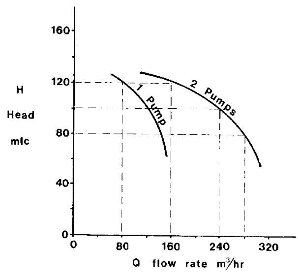
When gas carriers discharge, cargo tank pumps are usually run in parallel but where a refrigerated ship discharges to pressurised storage, cargo tank pumps are run in series with booster pumps. When pumps are run in parallel their individual performance curves can be combined to give, for example, a capacity/head curve for two, three or four pumps together.
Taking the pump characterised by Picture 3, the capacity/head curve for running two pumps in parallel can be easily plotted by doubling the flow rate available at the appropriate head for a single pump, as shown in Picture 4.
Similarly, when running three pumps in parallel the flow rate at the appropriate developed head can be obtained by multiplying the flow rate at the same head for a single pump by three. Thus, a series of curves can be built up from the curve of a single pump. When pumps are run in series, again the individual performance curves can be combined to give the appropriate curve for the series configuration. Picture 5 shows how this can be done using, for example, two pumps characterised by Picture 3 in series.
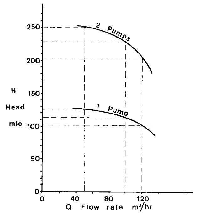
This time for each value of flow rate, the appropriate head developed by the pump is doubled to give the head developed by two pumps in series. The cargo flow rates achieved by any pump or combination of pumps will depend upon the backpressure encountered due to static head (difference in liquid levels of receiving tank and tank being discharged) and the resistance to flow in the connecting pipeline. To determine the flow rate in any particular circumstance the pipeline flow characteristic must be superimposed upon the pumping characteristic.
But suffice it here to note that because of the way back pressure rises steeply with increasing flow rate, pumps in series or in parallel will provide flow rates much less than may be initially imagined from the augmentation of mlc or volumetric flow capacity respectively of the series or parallel combination. The minimum necessary pumping power should be used in order to reduce heat input to the cargo and the rise in saturated vapour pressure of the delivered cargo.
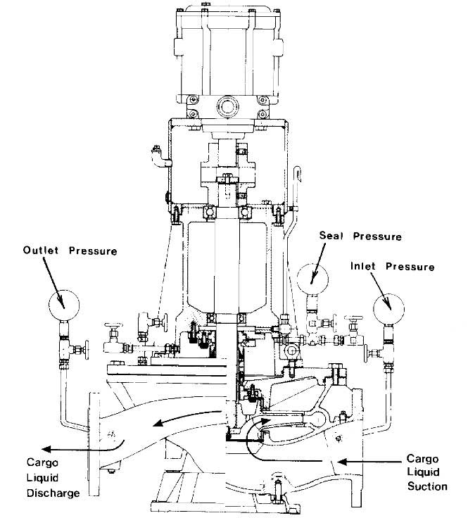
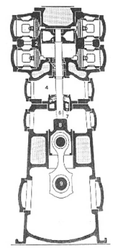
Deepwell pumps
Deepwell pumps are the most common type of cargo pump for LPG carriers. Picture 6 shows a typical deepwell pump assembly. The pump is operated electrically or hydraulically by a motor, which is flange-mounted outside the tank. The drive shaft is guided in carbon bearings inside the discharge tube and these bearings are in turn lubricated and cooled by the cargo flow up the discharge tube.
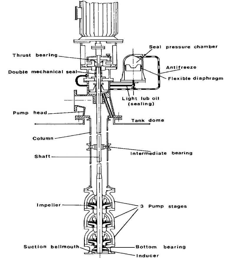
The impeller assembly is mounted at the bottom of the cargo tank and will frequently comprise two or three impeller stages together with a first stage inducer; this latter is an axial flow impeller used to minimise the NPSH requirement of the pump. The shaft sealing arrangement consists of a double mechanical seal with an oil flush. The accurate installation and alignment of the motor coupling, thrust bearing and mechanical oil seal is important.
Submerged pumps
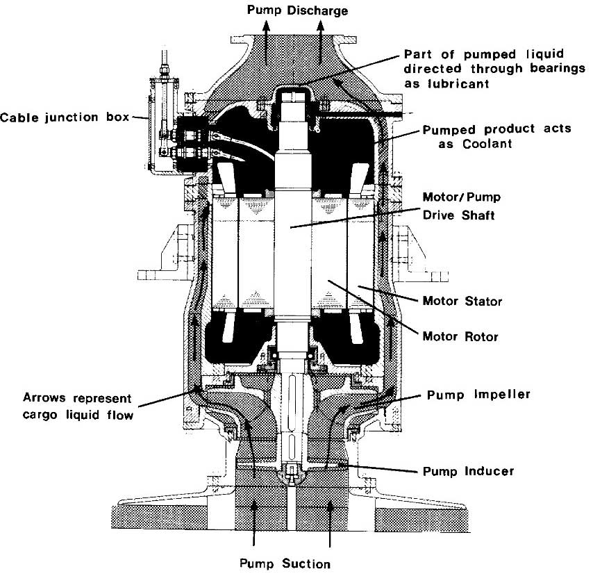
This type of pump is used on all LNG carriers, and on many of the larger fully refrigerated LPG carriers. The pump assembly and electric motor are close coupled and installed in the bottom of the cargo tank; power is supplied to the pump motor through copper or stainless steel sheathed cables, which pass through a gastight seal in the tank dome and terminate in a flameproof junction box. Submerged pumps and their motors are cooled and lubricated by the cargo and are therefore susceptible to loss of flow rate damage. Picture 7 shows a typical submerged pump/motor assembly.
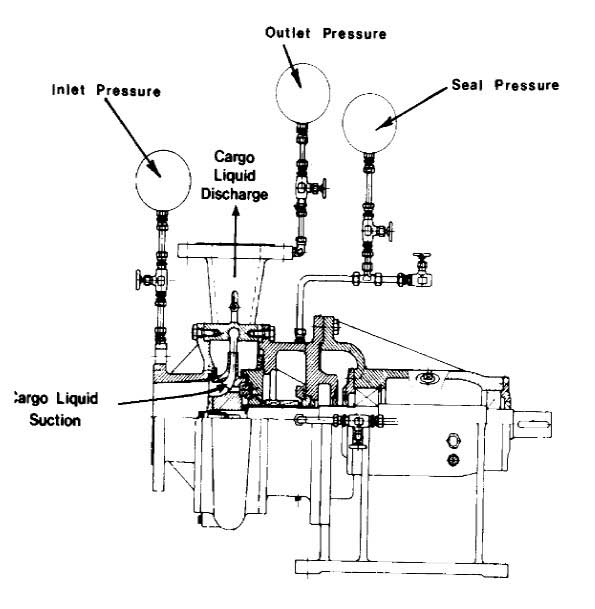
Booster pumps
Booster pumps are also of the centrifugal type and may be either vertical in-line pumps deck-mounted in the appropriate discharge line and driven by an “increased safety” electric motor or, alternatively, horizontal pumps installed on deck or in the cargo compressor room driven through a gas-tight bulkhead by an electric motor installed in the electric motor room. Pictures 8 and 9 show examples of these types of pump. The particular pumps shown are fitted with a double mechanical seal, which is methanol-flushed and pressurised between the seals.
Methanol injection to cargo pumps
The formation of ice or hydrates may occur in ships carrying refrigerated or semi-refrigerated LPG products or they may be transferred from shore during loading operations. Such formations may enter cargo pumps, block lubricating passages, unbalance the impeller or seize bearings. To prevent such damage, it is common practice to inject methanol, or an alternative freezing point depressant, into the cargo pump to facilitate de-icing. Because of the danger of methanol contamination to certain LPG cargoes, injection quantities should be strictly controlled. Cargo filters in the loading lines should remove hydrates from the shore. A small quantity of methanol is often injected into cargo pumps, especially submerged pumps, to ensure that any ice formed from moisture in the pump during initial cool down will be freed prior to starting the pump.
Cargo heaters and cargo vaporizers
A cargo heater is used to heat the cargo when discharging to an ambient shore tank. A cargo heater is also used when loading a fully pressurised gas carrier with cargo with temperature less than -10 °C. Seawater or oil is used to heat the cargo in the cargo heater. It is of importance to remember that the cargo heater is full of water and have good flow out with water before letting cold cargo into the heater. Fully pressurised gas carriers are carriers that are designed to transport condensed gases at ambient temperature, and they normally don’t have cargo cooling plant.
Heat exchanger
Heat exchangers are utilised in several different parts of cargo handling on gas carriers:
- as heat exchangers (cargo heater);
- condensers for cargo cooling plant;
- vapour risers;
- super heaters and oil coolers for compressors.
In most of the heat exchangers seawater is used as the medium on gas carriers, which the products are cooled or heated against.
The heat exchangers that are used for cargo handling must be designed and tested to tolerate the products the gas carrier is certified for. Heat exchangers that are used for cargo handling are considered as pressure vessels, and IMO requires one safety valve if the pressure vessel is less than 20 m3 and two safety valves if it is above 20 m3. All heat exchangers that are used for cargo handling must be pressure tested and certified by the gas carriers Class Company.
Heat exchangers where water is used as the medium and are utilised for heating have little or no effect with water temperature less than 10 °C. Seawater became ice at about 0 °C and starts to free out salt at about 50 °C. So with operating temperatures with a larger variation than from 10 °C to 45 °C, one ought to use another cooling medium than seawater.
Some terminals do not accept water as medium in heat exchangers, therefore one must either heat the cargo on route at sea or the gas carrier must have heat exchangers that do not use water as medium. It is of importance to ensure that the water out of a heat exchanger is never below 5 °C. These prevent the water in the heat exchanger from freezing and eventually damage the heat exchanger.
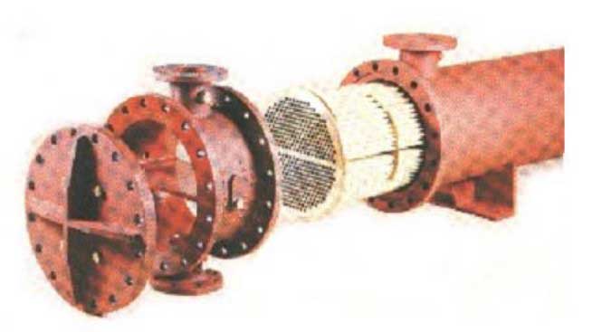
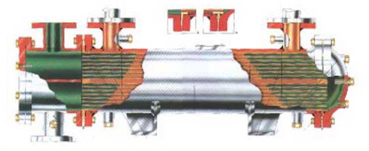
Tube heat exchangers
Tube heat exchangers are produced with tube bundles either as straightened pipes or u-formed pipes placed into a chamber. The pipes in the tube bundle have an inside diameter on 10 to 20 millimetres. There is a cover installed on each end of the chamber to clean the pipes more easily and maintain these. It is, at all times, important to ensure that the velocity of the liquid that is being pumped through the heat exchanger is not too high, to prevent cavity damage in the tube bundle or the end covers.
The tube bundle is made of:
- stainless steel;
- carbon steel;
- copper-nickel alloy;
- brass-brass alloy or titan.
Which choice of material one decides to choose, depends on the product one will operate and the costs associated with the investment and maintenance.
In tube heat exchangers, where seawater is used as medium, the product to be heated goes in the tube bundle. This prevents remaining seawater from freezing or prevents remnants of salt deposits inside the tubes. Tube heat exchangers must at regular intervals be cleaned to prevent particles from settling inside the tubes in the tube bundle or in the end covers. One must closely check for cavity damage when cleaning the heat exchanger. Ensure that the gasket is produced in a quality that tolerates the products and temperature one operates it with. Also, ensure that the gasket is correctly placed.
Plate heat exchangers
Plate heat exchangers are more utilised in cold storage plants on shore, for example in the fish industry and the meat industry. Plate heat exchangers are built with thin plates with double liquid channels. The plates are installed with the flat side toward each other. The cooling medium and product are pumped each way in the channels to achieve the best possible cooling or heating. Water or oil is used as the cooling medium and is dependent upon the temperature of the product that is to be cooled or heated. Plate heat exchangers are also used as condensers on newer cargo cooling plants aboard gas tankers.
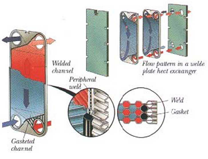
Plate heat exchangers must be cleaned at regular intervals to prevent the channels from clogging with salt deposits or particles from the medium or the product.
Reliquefaction systems and control of boil-off
With the exception of fully pressurised gas carriers, means must be provided to control cargo vapour pressure in the tanks both during loading and on passage. In the case of LPG and chemical gas tankers some form of reliquefaction plant is fitted; this plant is specifically designed to perform the following essential functions:
- To cool down the cargo tanks and associated pipe work before loading;
- To reliquefy the cargo vapour generated by flash evaporation, liquid displacement and boil-off during loading when there is no vapour return line to shore;
- To maintain or reduce cargo temperature and pressure within the prescribed design limits of the cargo system on passage.
There are two main types of liquefaction plant:
- Direct cycles – where the evaporated or displaced cargo vapour is compressed, condensed and returned to the tank. This is the most commonly used system, but may not be employed for certain gases. (See IMO Codes, Chapter 17).
- Indirect cycles – where an external refrigeration system is employed to condense the cargo vapour without it being compressed. This cycle is relatively uncommon, as it requires, for efficiency, a very cold refrigerant and large surfaces.
There are three main types of direct cycle:
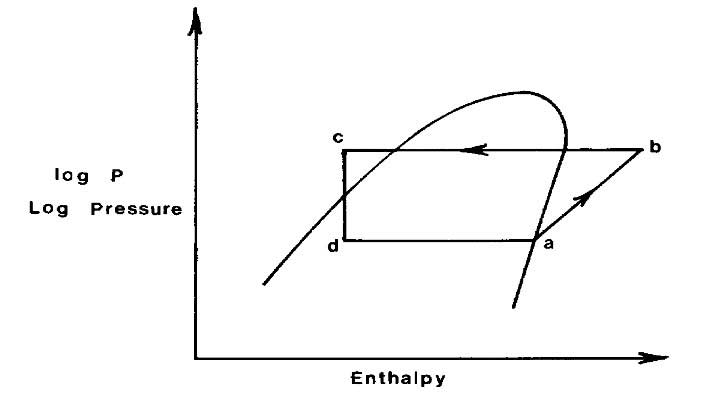
1 Single-stage direct cycle. A simplified flow sheet of a single compression stage reliquefaction cycle is shown in Pictures 10 (a) and (b). Where suction pressures are relatively high as in the carriage of semi-refrigerated products, then this cycle is suitable. Boil-off vapours from the cargo tank are drawn off by the compressor and compressed. The compression process increases pressure and temperature of the vapour allowing it to be condensed against seawater in the condenser.
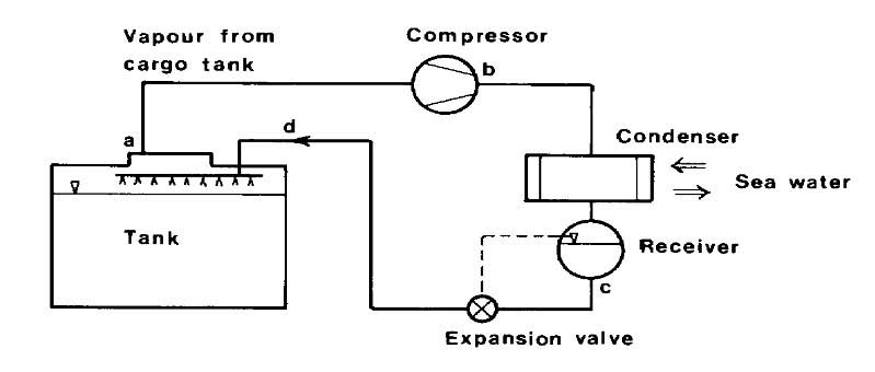
The condensed liquid is then flashed back to the tank via a float-controlled expansion valve. The returned liquid/vapour mixture to the cargo tank may either be distributed by a spray rail at the top of the cargo tank, or taken to the bottom of the tank to discourage revaporisation, depending on whether the tank is empty or full respectively.
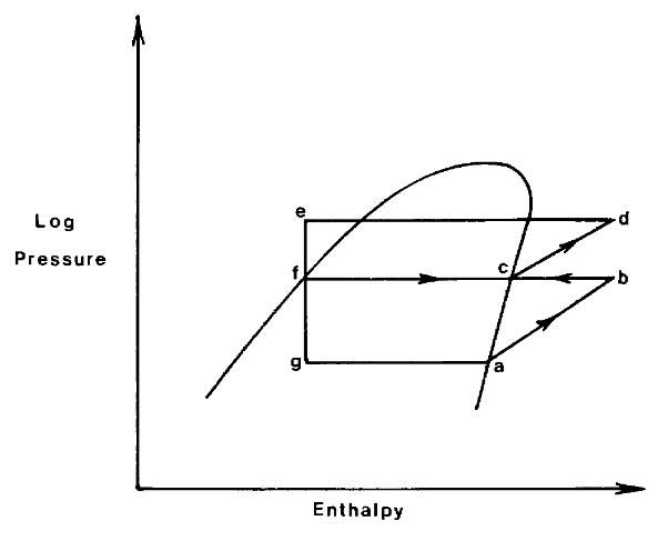
2 Two-stage direct cycle. A simplified flow sheet showing a two-stage direct cycle is shown in Pictures 11 (a) and (b). The two-stage cycle with inter-stage cooling is used where suction pressures are low and, as a result, compression ratios high (assuming sea water condensing) compared to the single-stage cycle. Two-stage compression with cooling between the stages is therefore sometimes necessary to limit compressor discharge temperatures, which increase significantly with increasing compression ratio.

The vapour from the first stage discharge is taken to an intercooler where its superheat is removed. The cooling medium is cargo liquid “flashed down” to intercooler pressure from the sea water-cooled condenser/receiver. The remaining parts of the cycle are similar to the single-stage cycle.
3 Cascade direct cycle. The cascade system uses a refrigerant such as R22 to condense cargo vapours; a simplified flow sheet is shown in Picture 12. The single-stage compression of cargo vapour is identical to the single-stage direct cycle, but the cargo condenser is cooled using R22 instead of seawater.

The cargo, in condensing, evaporates the liquid R22 and the R22 vapours are then taken through a conventional R22 closed refrigeration cycle condensing against seawater – hence the term cascade. The cascade cycle is used for fully refrigerated cargoes and plant capacities are not so affected by seawater temperature changes, as are other reliquefaction cycles.
Cargo compressors
Compressors are used as vapour pumps in all modern cargo cooling plants, either to compress or pump cargo vapour. Compressors are also used to compress or pump cooling medium as Freon vapour on indirect cargo cooling plant and cascade plant. The compressors in the cargo cooling plants are produced either as piston, screw or centrifugal type. We will now look at the different types of compressors and starting with piston compressors.
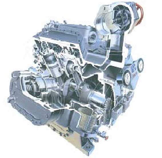
Piston compressors
Piston compressors used directly against cargo are of oil free type. Oil free compressors are used to prevent pollution of oil into the cargo, and thereby contamination of the cargo. All cargoes we are cooling demand a high rate of purity. Consequently, it cannot be mixed with oil or be polluted by other products. With an oil free piston compressor, we mean that the cylinder liners are not lubricated or cooled with oil.
Piston compressors that are used against Freon normally have Questions and answers to Crew Evaluation System Test about Marine Lubricantsoil lubrication of cylinder liners. Piston compressors are either built with cylinders in line, v-form or w-form. Compressors with cylinders in line are built with two or three cylinders either single-acting or double-acting. V-form compressors are built with two, four, six, eight or twelve cylinders and are single acting.
Double-acting compressors
Double-acting compressors are normally oil free and compress the vapour above and under the piston. The vapour is compressed on top of the piston when the piston goes up and vapour is sucked into the cylinder below the piston. The vapour is compressed below the piston when the piston goes down and is sucked into the cylinder above the piston. This indicates that each cylinder has two suction valves and two pressure valves. The pistons are equipped with compression grooves and are not equipped with piston rings.
There is no oil lubrication of the piston itself, but there is oil in the crankcase on the compressor. It is of importance that the sealing device between the cylinder liner and crankcase is intact. In the first stage, the oil pressure in the crank is checked and compared to the suction pressure and the cargo tank pressure.
Check the user manual for the cargo compressors and the marginal values for the pressure difference with oil and suction.
This type of compressor is used as cargo compressor onboard gas carriers. It is important to change the oil in the crank when changing cargo. This is to prevent pollution to the next cargo from the previous cargo. Small amounts of leakage between the cylinder and crank will at all times occur, so the oil in the crank contains some of the product that is cooled.
Single-acting compressors
Single-acting compressors compress and suck the gas on one side of the piston and then normally above the piston. A suction valve and pressure valve is then installed in the top of the cylinder. The cylinder top is spring-loaded as a safety precaution against liquid “knock”. The compressors are built with the cylinders in pairs: two, four, six, eight and twelve, then often as V-form or W-form. Single-acting compressors are used both as Freon and cargo compressors on gas tankers.
Piston compressors are operated by electric motor with direct transmission or strap transmission with a constant number of revolutions. The number of revolutions is between 750 to 1750 rpm. Unloading of the compressor occurs by hydraulic lifting of the suction valves. The drawback of piston compressors is that they are vulnerable when the cylinder liner is filled with liquid and they also have relatively low capacity for cooling. Onboard many gas tankers; there is a liquid receiver on the vapour line between the cargo tank and the cargo compressor, which prevents the liquid from being carried with into the compressor. The liquid receiver is equipped with a level alarm to control the liquid level.
Screw compressors
Screw compressors are either oil free or oil lubricated. The type used on the cargo side must be of oil free type for the same reason as the piston compressors.
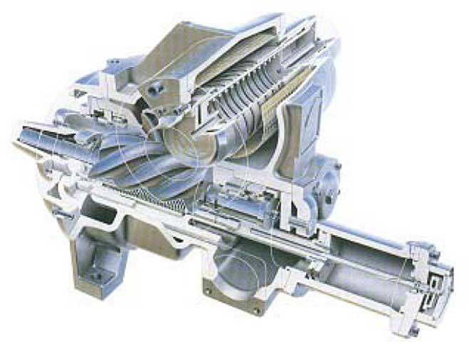
The principle for screw compressors are two rotating screws, the screw that operates has convex threads and the operated screw has concave threads which rotates them in different directions. Vapour is screwed through the threads and with rotation on the screws; the confined gas volume decreases successively resulting in compression. Please also refer to “cargo cooling process” for more information.
The advantage with screw compressors is that they wear few parts and have low weight in proportion to cooling capacity. Oil free screw compressors are operated by electric motors with a constant number of revolutions and have a gear transmission for the compressor, which has approx. 12 000 rpm. The high speed prevents leakage between the pressure and suction side. Screw compressors with oil injection in the rotor house have a lower number of revolutions, about 3 500 rpm. One can also use electric motors with direct shaft transmission.
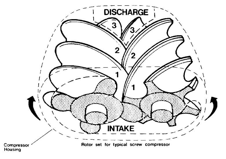
Oil free screw compressors
Screw compressors for use with liquefied gas cargoes can be either dry oil-free or oil-flooded machines. In the dry machines the screw rotors do not make physical contact but are held in mesh and driven by external gearing. Due to the leakage effects through the clearances between the rotors, high speeds are necessary to maintain good efficiency (typically 12 000 rpm).
Picture 13 shows a diagram of a typical rotor set with the common combination of four and six lobes. The lobes intermesh and gas is compressed in the chambers 1, 2, 3, which are reduced in size as the rotors turn. The compressor casing carries the suction and discharge ports. The oil-flooded machine relies on oil injection into the rotors and this eliminates the need for timing gears, the drive being transmitted from one rotor to the other with the injected oil acting as lubricant and coolant.
Because of the oil sealing between the rotors, gas leakage is much less and therefore oil-flooded machines can run at lower speeds (3,000 rpm). An oil separator on the discharge side of the machines removes oil from the compressed gas. Capacity control of screw compressors can be achieved in a number of ways, the most common being to use a sliding valve, which effectively reduces the working length of the rotors. This is more efficient than suction throttling. Screw compressors consume more power than reciprocating compressors.
Compressor suction liquid separator
It is necessary to protect cargo vapour compressors against the possibility of liquid being drawn into the compressor. Such a situation can seriously damage compressors since liquid is essentially incompressible. It is normal practice, therefore, to install a liquid separator on the compressor suction line from the cargo tanks, the purpose of this vessel being to reduce the vapour velocity and, as a result, allow any entrained liquid to be removed from the vapour stream. This separator vessel is fitted with high-level sensors, which set off an alarm and trip the compressor.
Purge gas condenser
Many reliquefaction plants are fitted with a shell and tube heat exchanger mounted above the cargo condenser. The purpose of this heat exchanger is to condense any cargo vapours which, mixed with incondensible gases such as nitrogen, have failed to condense at the pressure and temperature existing in the main condenser.
For example, commercial propane that may have two per cent ethane in the liquid phase, will have perhaps 14 % ethane in the vapour phase, ethane being the more volatile component. This can cause difficulties in a conventional sea water-cooled condenser.
Picture 14 shows a typical purge gas condenser system. The gases not condensed in the main condenser are displaced into the shell of the purge condenser. Here they are subjected to the same pressure as exists in the main condenser but to a condensing temperature equivalent to the outlet temperature from the expansion valve since the whole or part of this liquid passes through the tube side of the purge condenser.
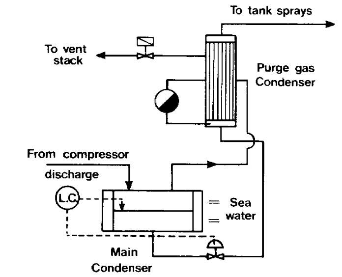
This lower condensing temperature allows cargo vapours to be condensed with any incondensible gases being purged from the top of the purge gas condenser by a pressure control system.
LNG boil-off and vapour handling systems
LNG ships use steam turbine-driven axial flow compressors to handle boil-off vapours produced during cool down, loading, loaded and ballast passages. Normally, a low-duty compressor handles the boil-off whilst on passage; a high duty compressor handles vapours produced during cool down and loading, returning these vapours to shore.
Whilst on passage the low-duty compressor collects the boil-off from a common header connected to each cargo tank, passes it through a steam heater to the poop front, whence it enters a specially designed double duct trunking system leading to the boiler fronts or diesel engine dual fuel systems. This trunking is continuously monitored for leakage and has automatic shut down protection in the event of system malfunction or leakage. The compressors are provided with surge controls and other protective devices.
Inert gas system
On gas carriers inert gas is used for different purposes, some are requirements other is to maintain the ships hull and spaces:
- Have neutral atmosphere in hold and inter barrier spaces.
- Elimination of cargo vapour from the cargo tank when gas freeing.
- Eliminating oxygen from the cargo tank before loading.
- Drying up hold spaces or inter barrier spaces to achieve a neutral atmosphere and to prevent corrosion in the spaces.
- Placing a neutral vapour above the cargo if required.
When carrying flammable cargo on fully refrigerated gas carriers there is a requirement to have a neutral atmosphere in the hold space or inter barrier space either with dry inert gas or nitrogen. If the gas carrier does not have an inert gas plant or nitrogen plant, it must have a storage vessel with inert gas or nitrogen with capacity of 30 days and nights consumption. The definition of consumption here is the leakage in the vents and manhole. If the cargo is not flammable we can have dry air, inert gas or nitrogen in the spaces.
If the cargo is Ammonia, one must not use inert gas that contains carbon dioxide, only dry air or nitrogen, because carbon dioxide reacts chemically with Ammonia. It is always beneficial to keep spaces around the cargo tanks dry.
Gas carriers use various forms of inert gas and these are listed below:
- Inert gas from combustion-type generators.
- Nitrogen from shipboard production systems.
- Pure nitrogen taken from the shore (either by road tanker or barge).
Unlike oil tanker inert gas systems, which have their design and operation established by extensive regulations and guidelines, the fitting of inert gas systems to gas carriers is subject to limited advice in the Gas Codes, special consideration by administrations and the particular demands of the trade. In general, for gas carriers, the production of combustion generated inert gas will be covered in new building specifications at about one per cent oxygen.
LNG ships were once provided with storage facilities for liquid nitrogen but newer designs include a nitrogen generation plant. However, up to now, the quantity of nitrogen produced on board has not been of sufficient volume for tank-inerting operations. It is fitted mainly for interbarrier space inerting. Where cargo tank inerting is required on LNG ships, nitrogen from the shore, or combustion-generated inert gas is used.
Most ships, barring only the smallest pressurised gas carriers, have the capability of generating their own inert gas. Furthermore, all LNG ships have the capability of producing nitrogen for hold space and interbarrier space inertion – this is a necessary specification, as the carbon dioxide in inert gas would freeze when in close proximity to the cargo. The methods of producing the inert gases, as listed at the beginning of this section, are covered below.
Inert gas generators
The Gas Codes require continuous oxygen monitoring in the inert gas stream and the oxygen content should normally be no more than about one per cent. High oxygen content can trigger an alarm; however, the generator is not normally shut down on this alarm but the gas is diverted to atmosphere via a vent riser.
The main advantages of the on board inert gas generator are as follows:
- The cost of inert gas is less than the purchase of liquid nitrogen.
- The inert gas plant capacity is available either at sea or in port.
The disadvantages of the combustion-type generator centre on the quality of gas produced. Combustion must always be carefully adjusted to avoid the production of toxic carbon monoxide and soot. Also, even under good operating conditions, the volume of oxygen in the inert gas may be unsuitable for use with the chemical gases. Accordingly, given that an oxygen-critical gas is to be loaded, as a preliminary operation, pure nitrogen must be taken from the shore.
Inert gas produced by the careful combustion of diesel or gas oil, results in a reduced oxygen content in the products of combustion. In the inert gas generator, the resulting gases are further treated to give an inert gas of acceptable standard. Apart from plant operation, the final quality of the inert gas also depends on the fuel used and generally fuel of low sulphur content is preferred. In this regard, experience often dictates that gas oil should be used in preference to marine diesel oil but bunker prices also have a bearing on the final choice.
The quality of the inert gas produced, however, is very dependent on the conditions under which the generator is operated and, in this respect, the manufacturer’s guidance should be closely followed. A particular point to watch is that poorly maintained plant can produce significant Quantities of carbon monoxide or soot such that, even after aerating, carbon monoxide levels in a tank may be unacceptable. The mode of operation is shown in Picture 15.
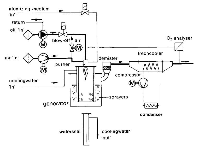
Here it will be seen that the inert gas generator has three main parts. These are as follows:
- A combustion chamber with scrubbing and cooling (the generator).
- A refrigerated drier – cooled normally by R22.
- An absorption drier.
Combustion chamber
Combustion-type generators must be located outside the cargo area and are usually installed in the ship’s engine room. It is usual to find the inert gas main permanently piped into the cargo holds and temporary connections are provided between the inert gas main and the cargo system for tank inerting operations. When not in use, these must be disconnected and blanks fitted. Two non-return valves (or equivalent) are fitted in the inert gas main to prevent any back-flow of cargo vapours. When not being used for high capacity tank inerting operations the inert gas plant is used from time to time to top up hold and interbarrier spaces.
Within the combustion chamber, the burner is designed to ensure good combustion so producing a minimum of oxygen residue in the inert gas. Operationally, however, there is a fine balance to be achieved in generator adjustment as minimising oxygen output tends to increase the production of carbon monoxide: and further adjustment can result in the overproduction of soot. The combustion chamber itself is water-jacketed.
After combustion, the inert gas enters the washing section of the generator at a very high temperature and is cooled and scrubbed by spraying with seawater. This is also carried out for the removal of soluble acid gases such as sulphur dioxide and the oxides of nitrogen. The inert gas is then filtered to remove solid particles. The gas leaves the generator at approximately five degrees Centigrade above sea water temperature and by this time it should be essentially free from sulphur oxides formed by burning the sulphur present in the fuel – but it is saturated with water vapour. Accordingly, it is then further cooled and dried (as covered below) and delivered to the cargo tanks.
The refrigerated drier
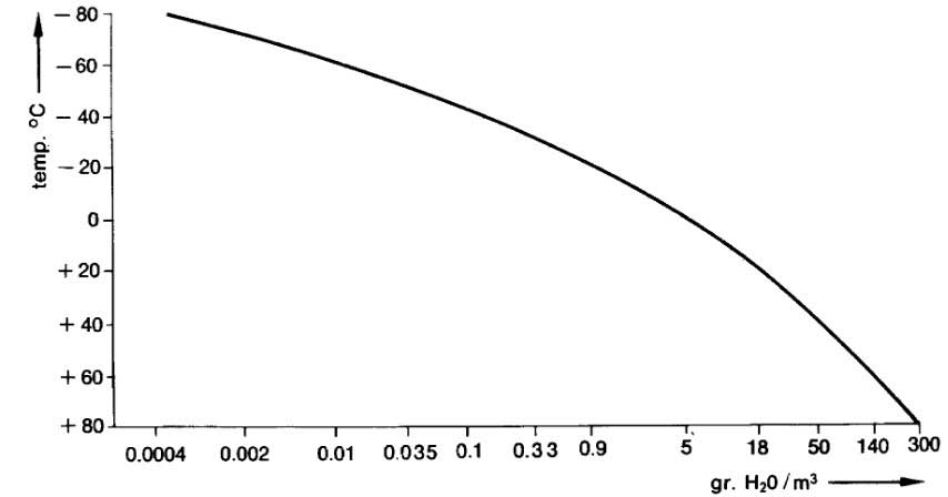
In the refrigerated drier, the inert gas is cooled to approximately four degrees Centigrade, resulting in the condensation of much of the water vapour. Picture 16 shows the content of water vapour in saturated inert gas as a function of temperature. From this diagram, the reduction in water vapour content can be seen as the temperature is reduced.
The absorption drier
The absorption drier consists of two vessels filled with activated alumina or silica gel. One vessel is on drying duty while the other is being regenerated. Typically, the cycle time is six hours.
Drying in the absorption drier reduces the dew point of the inert gas to -40 °C or below. A layer of molecular sieves can be added to the bottom of the drying tower to improve the dew point. In order to ensure stable combustion in the generator, the pressure in the drying system must be kept constant and this is achieved by means of a pressure control valve.
Nitrogen production on ships
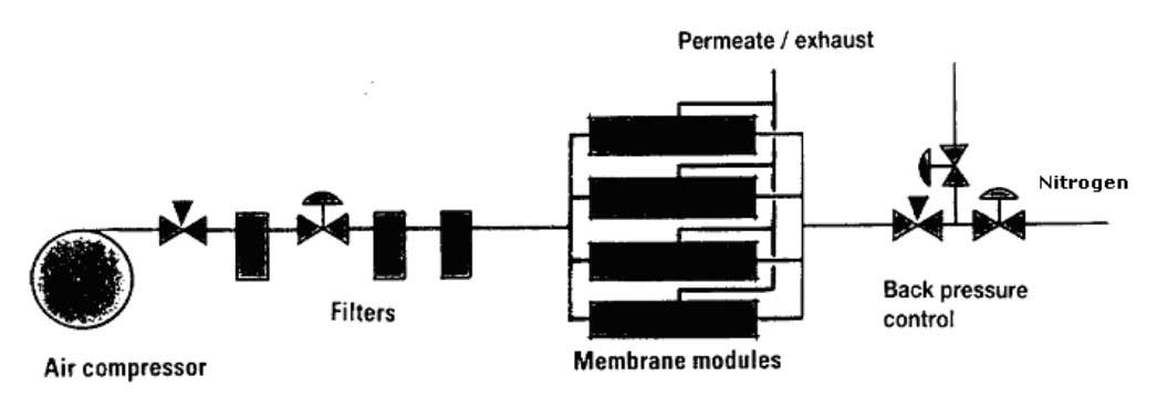
The most common system utilised for the production of nitrogen on ships is an air separation process. This system works by separating air into its component gases by passing compressed air over hollow fibre membranes. The membranes divide the air into two streams – one is essentially nitrogen and the other contains oxygen, carbon dioxide plus some trace gases. This system can produce nitrogen of about 95 to 97 % purity. The capacity of these systems depends on the number of membrane modules fitted and is dependent on inlet air pressure, temperature and the required nitrogen purity. Picture 17 shows one such system.
Pure nitrogen from the shore
The quality of inert gas produced by shipboard systems is usually inadequate for oxygen-critical cargoes – see strict in-tank oxygen requirements in “Table 3. Flammability range in air/oxygen for various liquefied gases”Properties and hazards of shipping LNG, LPG. Bearing in mind the components in the inert gas, this may create restrictions on use if tanks have been previously gas-freed for inspection; and this is often necessary when a change in grades is involved.
Under these circumstances, and prior to loading, it is normal for shipmasters to arrange for cargo tanks to be inerted with pure nitrogen, taken from the shore. Road tanker or barge usually delivers this. As deliveries are in liquid form, where immediate inerting is required, a nitrogen vaporiser is needed.
Instrumentation
A commonly used definition of area safety classification for electrical equipment in shore installations is as follows:
- Zone 0: An area with a flammable mixture continuously present.
- Zone 1: An area where flammable mixtures are likely to occur during normal operations.
- Zone 2: An area where flammable mixtures are unlikely to occur during normal operations.
The electrical installations of all gas carriers are subject to the requirements of the Flag Administration, the Classification Society and of IMO. Zones and spaces are classified as either “gas-safe” or “gas-dangerous” depending on the risk of cargo vapour being present.
For example, accommodation and machinery spaces are “gas-safe”, while compressor rooms, cargo tank areas and holds, etc. are “gas-dangerous”.
In gas-dangerous spaces, only electrical equipment of an approved standard may be used; this applies to both fixed and portable electrical equipment. There are several types of certified safe electrical equipment found on gas carriers.
Intrinsically safe (i.s.) equipment
Intrinsically safe equipment is defined as an electrical circuit of connected apparatus and wiring in which no spark or thermal effect under normal operation or specified fault conditions is capable of causing ignition of a given explosive mixture. Limitation of such energy may be achieved by placing a barrier in the electrical supply in the ‘safe’ area as shown in Picture 18.

Zener barriers are frequently used and in the circuit shown the voltage is limited by the Zener diodes, and the maximum current flow to the hazardous area is restricted by the resistors. The use of intrinsically safe systems is normally limited to instrumentation and control circuitry in hazardous areas. Because of the very low energy levels to which they are restricted, intrinsically safe systems cannot be used in power circuits.
Flameproof equipment
A flameproof enclosure is one which can withstand the pressure developed during an internal ignition of a flammable mixture and whose design is such that any products of the explosion occurring within the enclosure would be cooled below ignition temperature before reaching the surrounding atmosphere.
Therefore, the gap between flanged joints through which the hot gases are allowed to escape (flame path) is very critical and great care must be taken in assembly and maintenance to ensure that this flame path is maintained; no bolts must be omitted or tightened incorrectly; the gap must not be reduced by painting, corrosion or other obstructions.
Pressurised or purged equipment
This is a technique to ensure that an enclosure remains essentially gas-free either by pressurisation or by purging. In the case of pressurisation an overpressure of 0,5 mbar relative to the surrounding atmosphere must be maintained by leakage compensation while in the case of purged enclosure, a continuous supply of purging gas must be provided to the enclosure. Air or inert gas can be used.
Liquid level
Both the IMO Codes and Classification Society Rules require every cargo tank to be fitted with at least one liquid level gauge; specific types of gauging system are required for certain cargoes as defined in Chapter XIX of the IMO Code.
The IMO classification for gauging systems is as follows:
- Indirect systems – weighing or pipe flow meters.
- Closed devices which do not penetrate the cargo tank – ultrasonic devices or radioisotope sources.
- Closed devices which penetrate the cargo tank – float gauges, bubble tube indicators, etc.
- Restricted devices which penetrate the tank but which release small volumes of liquid or vapour when in use, such as fixed or slip, tube gauges. When not in use, the restricted device should be kept completely closed.
The most common types of level gauging on conventional gas carriers are those described in (3) and (4) above.
Float gauges
The float gauge is widely used in all tanker work and consists of a float attached by a tape to an indicating device which can be arranged for local and remote readout. Picture 19 shows a typical float gauge which is normally installed in a tubular well or with guide wires, with a gate valve for isolation so that the float can be serviced in a safe atmosphere.

The float must be lifted from the liquid level when not in use; if left down, the fluctuation in level at sea will damage the tape-tensioning device. Float gauges cannot normally register a liquid level of less than four inches in depth.
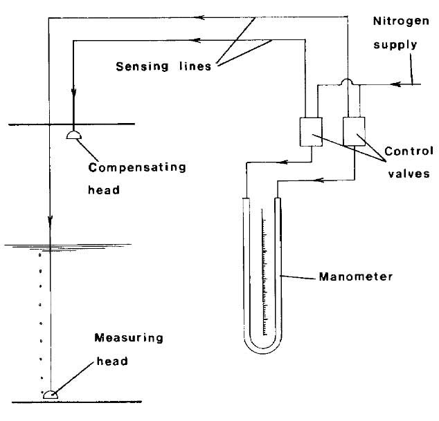
Nitrogen bubbler gauges
This system measures the pressure necessary to displace liquid from a small bore tube mounted vertically in a tank. Enough nitrogen is introduced into the tube to displace the liquid and just begin to bubble at the bottom. The pressure necessary to do this is measured and is a function of the liquid level and the liquid density. For cargoes of known density, level readout is obtained directly. By installing two such tubes alongside each other and with lower extremities a known vertical distance apart, the density of the cargo can also be determined. Picture 20 shows the principle of the bubbler gauge.
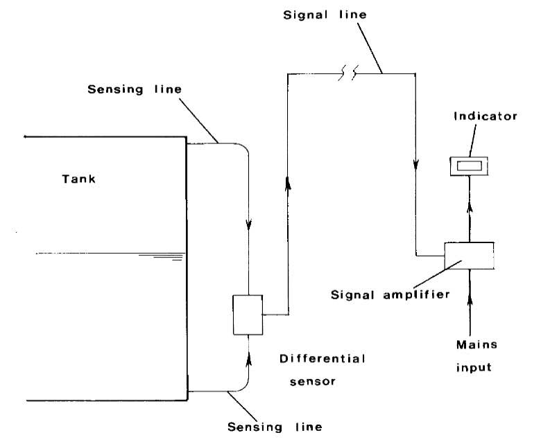
Differential pressure gauges
This device operates on differential pressure between liquid and vapour. The signal lines for the instrument are normally purged with inert gas. This type of gauge can only be used on ships when the tank is all above deck, thus it is more generally found in use ashore. Picture 21 shows the principle of the differential pressure gauge.
Capacitance gauges
This type of gauge measures the change in electrical capacitance between two probes as cargo liquid rather than vapour takes up the space between them. Picture 22 illustrates the device where the two probes enclosed within an open protective tube extend throughout the depth of the tank and provide a continuous indication of liquid content at all levels. For single preset level indication, as for a high level alarm or overfill shut-off, a short probe sensor may be fitted horizontally precisely at the level required.
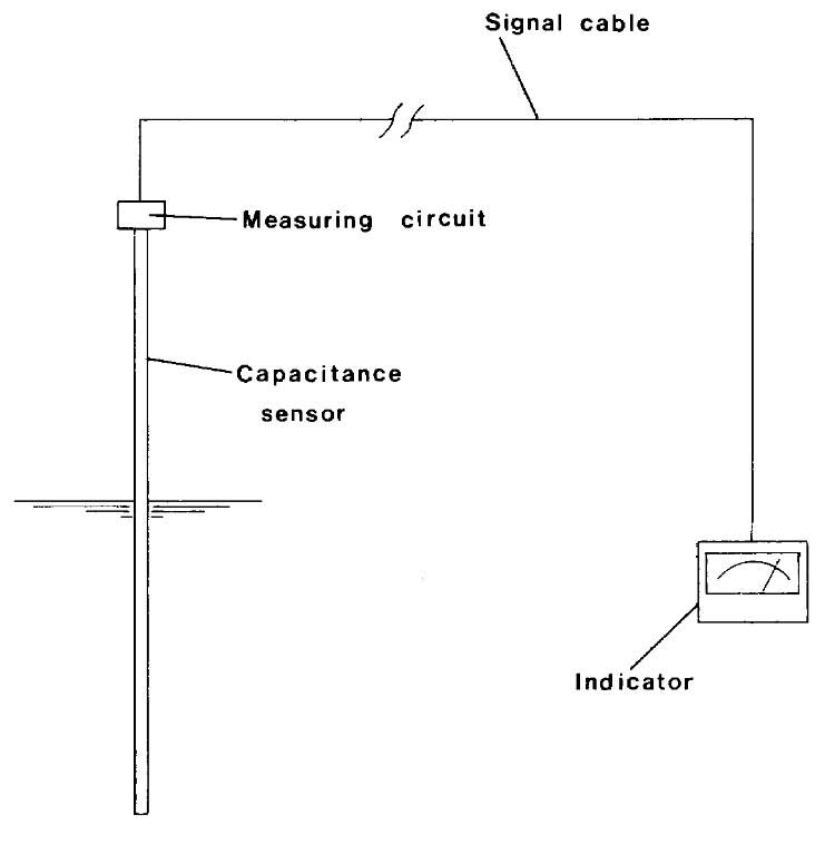
The electrical circuits are, of course, intrinsically safe and the devices, having no moving parts, are very reliable but must be kept free of dirt, rust and water/ice since such contaminants will cause inaccuracy.
Radar gauges
Another type tank gauging equipment is that designed to operate in the principle of radar. Such equipment works at very high frequencies – approximately 11 gigahertz. Radar type liquid level gauges have now been specially developed for liquefied gases and their usage on gas tankers. The equipment provides measurements adequate to meet industry requirements.
Level alarm and automatic shutdown systems
With the exception of Type C tanks whose capacity is less than 200 m3, every cargo tank must be fitted with an independent high-level sensor giving an audible and visual alarm. Float, capacitance or ultrasonic sensors may be used for this purpose. This high level alarm or other independent sensor is required automatically to stop the flow of cargo to the tank. During cargo loading there is a danger of generating significant surge pressure if the valve stopping the flow closes too quickly against a high loading rate and when no other tank is open to the flow.
Pressure and temperature monitoring
The IMO Codes call for pressure monitoring throughout the cargo system including:
- cargo tanks;
- pump discharge lines;
- liquid and vapour crossovers, etc.
In addition, pressure switches are fitted to various components to protect personnel and equipment by operating alarms and/or shutdown systems.
The IMO Codes also require at least two devices for indicating cargo temperatures, one placed at the bottom of the cargo tank and the second near the top of the tank, below the highest allowable liquid level. It is necessary to be aware of the lowest temperatures to which the cargo tanks steel can be exposed and these values should be marked on the temperature gauges.
Where cargo is carried in Type A tanks below -55 °C, the IMO Codes call for temperature-indicating devices within the insulation or on the hull structure adjacent to the cargo containment systems. The devices should be set to provide adequate warning prior to the lowest temperature for the hull steel being approached.
The Codes also call for temperature devices to be fitted to certain tanks in order to monitor the cargo system during cool down and warm-up operations to avoid undue thermal stresses being set up.
Gas detection systems
The provision of efficient gas detection systems on board gas tankers is of great importance. The IMO Codes call for every gas carrier to have a fixed gas detection system with audible and visual alarms on the navigating bridges in the cargo control room and at the gas detector readout location.
Detector heads must be provided in the following:
- (a) Cargo compressor room.
- (h) Electric motor rooms.
- (c) Cargo control rooms unless classified as gas-safe.
- (d) Enclosed spaces such as hold spaces and interbarrier spaces excepting hold spaces containing Type C cargo tanks.
- (c) Air locks.
- (f) Vent hoods and gas to E.R. supply ducts (LNG ships only).
The detector heads should be sited with due regard to the density of the vapours of the cargo being carried, i.e. heavier than air vapours at low level and lighter-than-air vapours at high level. The sensing units from the gas detection system are normally located in the cargo control room, if fitted, or the wheelhouse.
Provision should be made for regular testing of the installation; span gas of a certified mixture for calibration purposes should be readily available and permanently piped if possible. Sampling and analysing from each detector head is done continuously and sequentially; the Codes call for sampling intervals from any one space generally not exceeding 30 minutes. Alarms should be activated when the vapour concentration reaches 30 % LFL.
In addition to the fixed gas detection system, every vessel must have at least two sets of portable gas detection equipment, together with means for measuring oxygen levels in inert atmospheres. It is of fundamental importance that all personnel on gas carriers are familiar with gas detection equipment and its operating principles. Manufacturer’s instructions should always be fully read and understood.