Discover the meticulous process of LNG tanks preparation for cargo loading on LNG vessels, including tank cleaning, drying, nitrogen purging, and inerting.
- Normal trading cycle of an LNGC
- Cargo Tank Cleaning
- Hold Space and Cargo Tank Drying
- Drying hold spaces on Moss type LNG carriers
- Drying insulation spaces on membrane type LNG carriers (Mark III and NO96)
- Drying the insulation spaces of NO96 cargo containment system
- Drying of cargo tanks
- Nitrogen Purging of Containment System
- Drying and inerting of tank insulation and annular space (Moss spherical type)
- Nitrogen purging the interbarrier and insulation spaces (membrane type – GTT Mark III only)
- Nitrogen purging the interbarrier and insulation spaces (membrane type – NO96)
- Other considerations when purging the interbarrier and insulation spaces for membrane type LNG carriers
- Inerting of Cargo System
From Moss-type to membrane-type LNG carriers, this guide outlines essential steps for ensuring safe and efficient operations in the LNG industry.
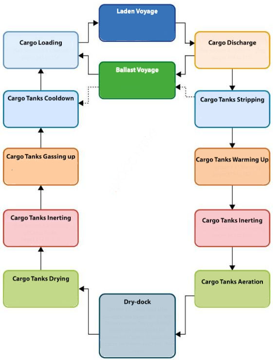
Normal trading cycle of an LNGC
The trading cycle of an LNGC will vary according to charter arrangements and could be a long-term charter for operations between a designated loading terminal and receiving terminals, or it could be an LNGC trading on the spot market and conducting loading and discharge operations at any terminal and/or in STS operations.
The normal trading cycle of an LNGC is as shown in the flowchart below:
Cargo Tank Cleaning
Reference: SIGTTO “LNG Shipping Suggested Competency Standards”, Sections:
1 Have an awareness of the requirement for cleanliness of cargo tanks.
2 Know and understanding the requirement and methods for cleaning cargo tanks:
- foreign objects;
- damage to containment system.
With so much in-tank equipment, coupled with the fact that cargo tanks are not (under normal circumstances) entered between refits, initial cleanliness is essential. Any debris drawn into an in-tank pump could cause serious damage to the rotating parts and access for repair could result in costly down time for an LNGC.
Level measuring systems, float gauges, temperature sensors and independent spot level transducers need to operate in an environment free of debris. With an average period of 2,5-5 years between repairs, and with conceivably as many as 50-100 cargoes loaded/discharged in that period, cargo tank cleaning (post refit) and maintaining high levels of cleanliness in-service are critical.
What makes gas freeing and entering an LNGCs tanks so different from another “conventional” type of tanker?
Unlike a conventional oil/product carrier, gaining access into an LNG cargo tank while in service involves warm-up, inerting and aeration, then facilitation of repairs to materials/equipment that will operate under cryogenic conditions 1 post-repair cleaning/inspection, re-inerting, gassing up and a full cooldown. The whole process is extremely expensive, and time consuming.
To reduce the risk of damage to the containment system during in-tank cleaning operations, the following guidance should be observed.
Considerations when entering an LNG cargo tank:
- the number of persons entering an LNG cargo tank must be strictly controlled at all times during the refit/repair period. An experienced person familiar with LNG tank entry should be present at all times;
- all entrants must be attired in clean boiler suits, disposable protection over footwear and gloves. No loose items should be taken into the tank;
- on completion, the cargo tank will need to be swept clean and vacuumed over all exposed surfaces that have the potential to retain debris, no matter how fine;
- an experienced person (C/O and/or Superintendent) will be designated to ensure that the required standard of cleanliness has been achieved and recorded. The tank will then be closed up and no further entry will be permitted;
- cargo lines and their associated equipment should be managed with the same cleanliness criteria;
- any debris found on entry into a cargo tank should be removed for examination and accounted for.
In-service cleanliness
Contamination of an in-service cargo tank can only occur via:
- contamination taken on board during the loading process, i. e. across the manifold from the terminal. This is prevented by in-line loading filters fitted in the ship’s manifold, typically a size 60 or 100 mesh;
- contamination from the ship, usually as result of equipment/material failure, i. e. Teflon valve seat, corrosion, etc. Again 60/100 mesh discharge filters are fitted in the ship’s manifold so the debris is contained and not passed to the receiving terminal. Some terminals or customers may require 200 mesh filters for the first discharge or first loading from a new train.
Pressure differential across the manifold filters is a parameter that should be monitored on board during the loading process. Remember that it might be ice formation rather than debris that causes a partial blockage.
After each loading/discharge operation the manifold filters should always be inspected by the ship (this includes the warming-up operations).
Hold Space and Cargo Tank Drying
Reference: SIGTTO “LNG Shipping Suggested Competency Standards”, Sections:
1 Have an awareness of the requirement and methods of drying hold spaces and cargo tanks.
2 Know and understand the correct line up of supply and exhaust valves and pipelines.
3 Know and understand the operation of inert gas plant to deliver dry air:
- temperature and dew point requirements for supplied air;
- alarm set points.
4 Monitoring procedures and analyse locations:
- dew point monitoring.
5 Parameters used to determine operation completed.
Drying hold spaces on Moss type LNG carriers
After having been opened for dry-dock or inspection, the hold spaces on Moss type LNGCs will contain a certain amount of moist air. This must be dried prior to re-entering service and before LNG is loaded into the cargo tanks to avoid any moisture penetration into the tank insulation (which would result in cold spots). Moss LNGCs are provided with a hold space heating and drying system to dry out these spaces, removing moisture and preventing any dew forming, therefore preventing corrosion. Dry air is introduced into the hold space through the IG filling pipeline. The displaced air is expelled from the top of each hold, via the vent mast, to atmosphere.
Procedure for drying the hold spaces on Moss type ships:
- ensure the IG plant is operating in the dry air mode, discharging to atmosphere;
- open the vent valves to the holds;
- open the inlet valves to the holds;
- on the IG panel, once the O2 level is satisfactory (20,9 %) and the dew point is at minus 45 °C (-45 °C) the IG system will automatically open the valve to allow dry air to pass into the aeration header and close the discharge to atmosphere valve;
- monitor the dew point of each hold space by taking a sample at the outlet pipe. When the dew point is at least minus 25 °C (-25 °C), close the filling valves and close the vent valve;
- when all holds have been purged with dry air, return the IG plant to “deliver IG” mode and shut down the IG plant.
Drying insulation spaces on membrane type LNG carriers (Mark III and NO96)
Overview
Prior to the first loading after dry-dock, insulation spaces have to be dried with N2. Cargo tanks must be at a positive pressure, slightly above the atmospheric pressure, prior to pressurisation of the insulation spaces.
N2 provides a dry and inert medium that allows detection of an LNG leak in the insulation spaces while preventing corrosion and detering the migration of any leaking LNG vapour from primary to secondary spaces.
Removing ambient humid air from the insulation spaces of Mark III cargo containment system
LNGCs fitted with the Cargo System – Tank ConstructionMark III containment system are not equipped with vacuum pumps to prevent damage to the triplex secondary barrier.
As the provision of vacuum pumps is not feasible on Mark III, to remove the ambient humid air from the insulation spaces, the by-pass valves on the exhausts from the interbarrier and insulation spaces need to be opened and a continuous supply of N2 provided so that the spaces are “swept” with a free flow of N2.
Once the exhaust from the spaces meets the criteria (O2 < 3 % by volume and dew point of at least < minus 25 °C (-25 °C), the exhaust by-pass valves are closed and the spaces are pressurised.
Note: in all cases the detailed instructions and specific values are in the manuals available on board (cargo operating manual, GTT procedures (incl. latest recommendations) and ship specific cargo information book). These should be followed as there may be slight differences in the operating procedures required.
Drying the insulation spaces of NO96 cargo containment system
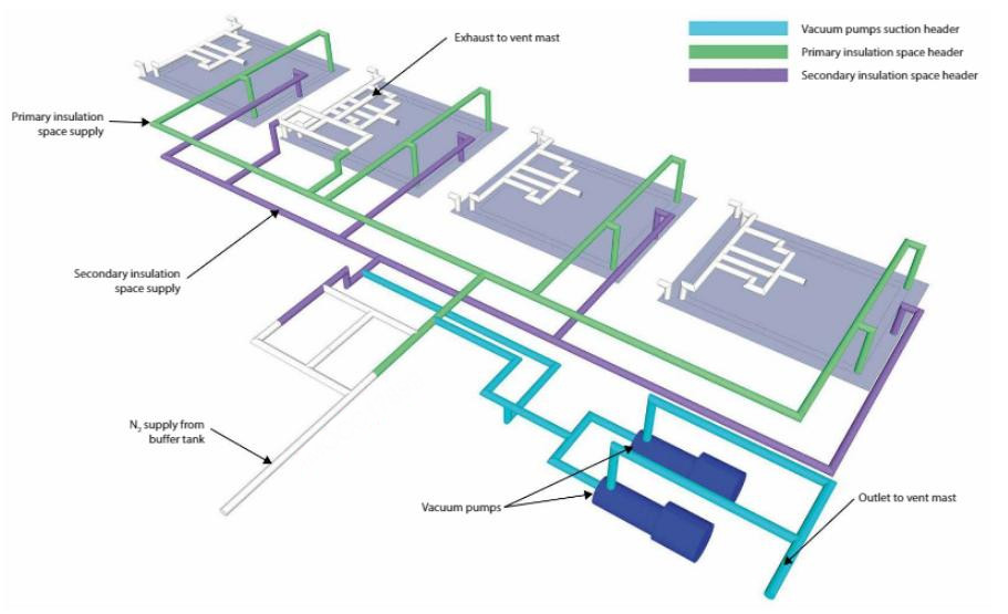
Ambient humid air is removed from the insulation spaces of NO96 cargo containment system by use of the ship’s vacuum pumps.
The process is repeated until the O2 content is reduced to < 3 % by volume and the dew point to at least < minus 25 °C (-25 °C).
Typically, evacuation of the insulation spaces will take approximately 8-12 hours. Three evacuation cycles may be necessary to reduce the O2 content to < 3 % by volume.
The procedure for evacuating the insulation spaces is also used to check the integrity of the barriers during the “periodic global test”. Precautions to avoid membrane damage must be in place.
Barriers should never be pressurised unless there is positive pressure in the cargo tank, i. e. the cargo tank should be slightly above atmospheric pressure. This is achieved by introducing dry air into the cargo tanks.
To avoid major damage to the cargo containment system:
- never evacuate a primary insulation space while the associated secondary space is under pressure;
- never pressurise a secondary space while the primary space is under a vacuum.
Note: severe damage to the membranes can occur if the differentials exceed 30 mbar.
The primary barrier is always maintained at a higher pressure than the secondary barrier to prevent damage to the containment system. The following should be considered:
- equipment, including measurement devices (gas sampling, gauges, etc.), that may be damaged during this operation should be isolated and it will be necessary to instal temporary manometers to monitor the pressure in the spaces concerned;
- at all times, the barrier spaces must be protected against over-pressure, which would otherwise result in membrane damage;
- two vacuum pumps, installed in the cargo compressor room, draw from the appropriate barrier spaces and discharge to the atmosphere via a vent mast.
Note: environmental changes in temperature or atmospheric pressure can produce differentials far in excess of 30 mbar in insulation spaces that are isolated.
After evacuation, the next step (or cycle) is to fill the insulation spaces with N2. Repeat the cycle until the O2 content in the spaces is < 2 % by volume.
The N2 is supplied from the ship’s N2 generators. Prior to commencing this operation, ensure that they are fully operational and that the dew point is within acceptable limits for the containment system, i. e. < minus 25 °C (-25 °C). The procedure is as follows:
- adjust the opening of the insulation space supply valves to control the pressure rise;
- during filling, monitor to ensure the pressure in the primary space is always above the secondary space;
- carry the final filling of the insulation spaces at a reduced rate of flow.
Note: GTT recommends a very slight control range overlap between the make-up and exhaust regulating valves to ensure a continuous minimal N2 flow through the space.
Drying of cargo tanks
On entering service after construction or a dry-dock repair period, the cargo tanks will contain humid air and so must be dried to prevent the formation of ice as they are cooled down with LNG that is at minus 162 °C (-162 °C). This also avoids formation of corrosive agents if the humidity combines with the sulphur and nitrogen oxides, which might be contained in the IG.
Drying removes moisture from cargo tanks, pipework, etc. to reduce the dewpoint and minimise problems of ice formation.
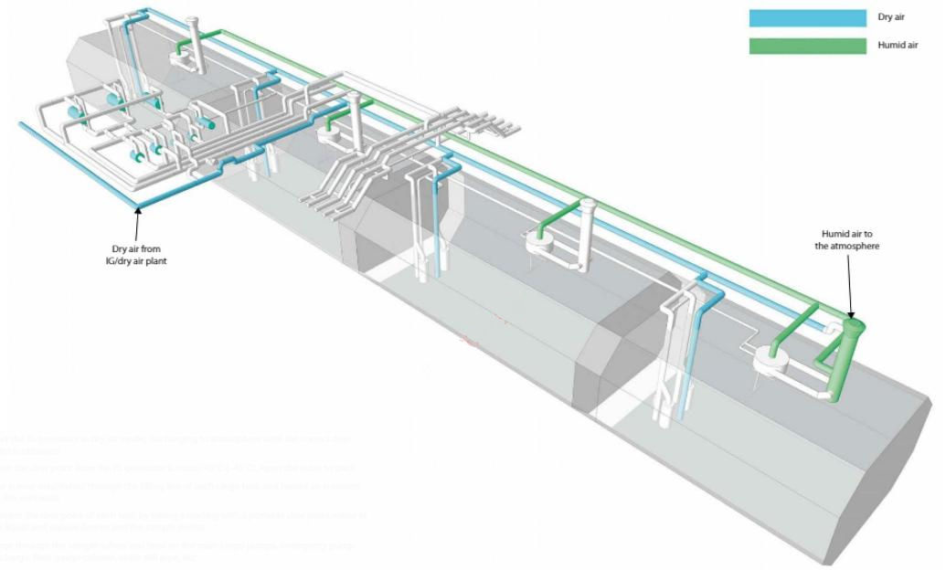
Before the IG/dry air line is connected to the cargo system, blow it through with air using the IG blower to avoid any debris entering the cargo system. This is particularly important when initial operations are carried out after a new LNGC has entered into service.
Dry air from the IG plant is introduced to the bottom of the cargo tanks using the loading lines. The tank atmosphere is displaced from the top of the tank through the dome arrangement, into the vapour header and discharged through the appropriate vent mast, usually No. 1 (for’d).
This operation can be conducted in a number of different ways:
- drying one tank at a time;
- drying all tanks simultaneously.
During the period that the IG plant is in operation for the drying (and subsequent inerting) of the cargo tanks, IG is also used to dry and inert all other LNG and vapour pipework to below minus 45 °C (-45 °C).
On a Cargo containment system of gas vessel4 tank membrane ship of 140 000 m3 it will take 20 hrs to dry all the tanks to a dew point of approximately minus 25 °C (-25 °C), or as otherwise specified in the cargo operating manual.
For a 30 000 m3 cargo tank, the amount of water vapour can be between 100 kg and 400 kg, depending on the environmental conditions.
A modern shipboard IG plant (with silica gel drying facilities) can, typically, produce dry air with a dew point of minus 45 °C (-45 °C) and a flow rate of up to 16 500 m3/h.
Before the introduction of LNG or its associated vapour, any pipework not purged with IG must be purged with N2 from the onboard N2 generating plant.
| Preparation for Drying Cargo Tanks | Line up of the cargo piping must be as per the ship’s specific |
| A detailed plan of the operation must be prepared | Open the valves to supply dry air to the liquid header |
| Measuring devices (dew point meters) must be checked and calibrated prior to operation | Open the tank vapour valves |
| Set the IG/dry air plant for use in dry air mode | Open the tank filling valves |
| It will be necessary to fit a spool piece connecting the IG/dry air line with the liquid header line (this operation may take several hours) | Line up the vapour header to the vent mast |
| Connect the inert gas line to the cargo liquid line | |
| Prepare the inert gas plant for use in the dry-air mode and discharge to atmosphere | |
| Open vapour main to the forward vent riser |
Operational description – cargo tanks drying
- start the IG generator in dry air mode, discharging to atmosphere until the correct dew point is obtained;
- when the dew point from the IG generator is minus 45 °C (-45 °C), open the valve to deck;
- flow is now established through the filling line of each cargo tank and humid air is vented via the vent mast;
- monitor the dew point of each tank by taking a reading with a portable dew point meter at the liquid and vapour domes and the sample point;
- purge through the sample valves and lines on the main cargo pumps, emergency pump discharge, float gauge column, radar still pipe, etc.;
- purge through the spray header and spray pumps;
- the compressors, vaporisers, heaters and manifolds must be purged through, with a dew point reading taken at the sample points to ensure parts of the system have been dried;
- where there are blank flanges, these should be slackened off to allow the section of the line to be purged and dried;
- when the dew point measured in these cargo tanks is minus 25 °C (-25 °C) or less, filling and vapour valves of the tank are dosed (change over dry air flow to the atmosphere);
- when all the tanks are dried, stop the IG/dry air plant;
- close the supply valve to the liquid header and dose the venting system at the vent mast.
With most pipeline configurations, preparations for the drying and subsequent inerting procedures involve the fitting of 3 cross-over spool pieces into the cargo piping system. These are:
- IG/dry air plant to liquid header (already fitted before drying);
- IG/dry air plant to compressor house (already fitted before drying);
- IG/dry air plant to vapour header.
Note: fitting of such spool pieces is dependent on the ship’s cargo piping configuration and whether or not an onboard IG/dry air plant is fitted. In each case, you must follow the directions contained in the ship’s cargo operations manual.
Nitrogen Purging of Containment System
Reference: SIGTTO “LNG Shipping Suggested Competency Standards”, Sections:
1 Have an awareness of the requirement and methods of nitrogen purging.
2 Know and understand the different procedures required on spherical and membrane vessels.
3 Know and understand the correct line up of supply and exhaust valves and pipelines:
- options regarding exhaust gases.
4 Know and understand the operation of nitrogen generators:
- temperature and dew point requirements for supplied N2 alarm set points.
5 Know and understand monitoring procedures and locations:
- correct operation of inlet and exhaust valves;
- use of supply bypass valves:
- dangers.
6 Know and understand parameters to determine operation completed:
Before putting a cargo tank into its initial service, or after dry-docking, it is necessary to replace the ambient humid air in the insulation space with dry N2.
Drying and inerting of tank insulation and annular space (Moss spherical type)
The insulation around the cargo tanks on Moss type LNGCs is part of the leak protection system. The insulation is fitted such that there is a space between the tank material and the insulation, known as the annular space. In the event of a leak of vapour from the tank, it will be transported around the annular space to the gas detector by a constant flow of NP enabling the leak to be detected quickly. The insulation acts as a splash back, directing the liquid into the drip tray located beneath the tank. Prior to introducing cargo vapour or liquid into the cargo system, the insulation and annular spaces around the tanks are purged with N2. This removes any moisture that may be present within the insulation as well as the O2 in the atmosphere, resulting in an inert atmosphere around the tank.
Read also: Preparation of loading and unloading operations for LNG/LPG carriers
This procedure is undertaken by opening the exhaust valves from the annular spaces to atmosphere and then opening the by-pass valves on the N2 supply to the spaces on each tank. N2 is then supplied from the nitrogen generators as required. The process is complete when the O2 content is < 2 % and the dew point is < minus 25 °C (-25 °C).
Once complete, the nitrogen inlet by-pass valves are closed and the N2 supply to the annular spaces is regulated by the appropriate control valves.
Nitrogen purging the interbarrier and insulation spaces (membrane type – GTT Mark III only)
On GTT Mark III LNGCs, by-pass valves and exhaust valves from the interbarrier and insulation spaces are opened, which allows a continuous supply of N2 to be provided such that the spaces are “swept” with a free flow of N2. Once the exhaust from the spaces meets the set criteria, the exhaust by-pass valves can be closed and the spaces, pressurised.
Nitrogen purging the interbarrier and insulation spaces (membrane type – NO96)
Evacuation of the insulation spaces will take approximately 8 hours. Three cycles are usually necessary to reduce the O2 to < 2 % by volume.
Before being refilled with N2, the insulation spaces are evacuated to a vacuum of 200 mbar Absolute.
To avoid possible damage to the secondary membrane, the secondary insulation spaces must be evacuated before the primary insulation spaces. In normal design, the pipework at the vacuum pump’s suction ensures that either the evacuation of the primary spaces cannot take place without having first evacuated the secondary spaces or that both primary and secondary insulation spaces are evacuated simultaneously.
Two electrically driven vacuum pumps (installed in the cargo compressor room) draw from the appropriate headers and discharge to the vent riser.
After evacuation, the next step (or cycle) is to fill the insulation spaces with N2. Repeat the cycle until the O2 content in the spaces is < 2 %.
The pressure values and procedures for purging are contained within the ship specific cargo operating manual. An example operation may be as follows:
- adjust the opening of the primary space supply valves to balance the pressure rise in all of the spaces;
- during filling, maintain the pressure in the primary space at a higher pressure than the secondary space;
- when the pressure in the primary spaces reaches normal operating value (usually about 10 mbar) crack open the secondary space supply valves on each tank. Again, adjust the opening of these valves to balance the pressure rise in all the spaces.
Other considerations when purging the interbarrier and insulation spaces for membrane type LNG carriers
At all times, the barrier spaces must be protected against over-pressure as this could cause membrane failure.
Changes in temperature or barometric pressure can produce differentials far in excess of 30 mbar in insulation spaces that are isolated. With the cargo system out of service and during inerting, always maintain the secondary insulation space pressure to a level at or below the primary insulation space pressure. Severe damage to the membranes may result if the differentials exceed 30 mbar.
The final filling of the insulation spaces up to 2 mbar is carried out at a reduced rate of flow. Three cycles are usually necessary.
After the final filling, check the O2 content in all the spaces. If it is higher than 2 %, repeat the inerting operation. Also check the O2 content at the vacuum pump discharge at regular intervals.
Although the N2 is very dry, the final humidity of the insulation spaces is also an important matter for consideration. As with the O2, on completion confirm it as acceptable, i. e. dewpoint < minus 25 °C (-25 °C).
The primary and secondary insulation spaces are filled with dry N2 gas. This is automatically maintained by alternate exhaust and make-up valves as the atmospheric pressure or the temperature rises and falls. It is necessary to maintain pressures of between 2 mbar and 4 mbar above atmospheric pressure.
Ensure that all relief valves have been reinstated and any blanks are removed. To prevent membrane damage, vigilance, careful planning and tight operational control are essential at all times.
N2 is produced by the two N2 generators and is stored in a pressurised buffer tank, commonly 22 m3 in size. Depending on the system, there may be one or more tanks.
This supplies the primary and secondary supply or pressurisation headers through make-up regulating valves located in the cargo compressor room. From the headers, branches are led to the primary and secondary insulation spaces of each tank. Excess N2 from the insulation spaces is vented to the appropriate mast riser through the exhaust regulating valves.
Note: where there is no N2 flow, there is no gas detection for the space.
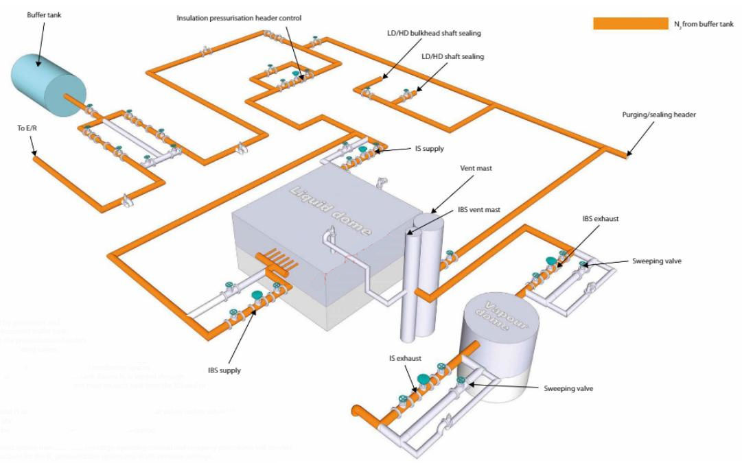
Interbarrier and insulation space (IBS/IS) N2 pressurisation and control system
N2, produced by generators and stored in a pressurised buffer tank, is supplied to the pressurisation headers through inlet regulating valves.
From the headers, branches are led to the interbarrier spaces (IBS) and insulation spaces (IS) of each tank. Excess N2 is vented through regulating exhaust valves to the N2 vent mast on each tank from the IBS and to atmosphere from the IS.
Both the IBS and IS of each tank are provided with pressure relief valves (safety valves) that open at a pressure above atmospheric of 30 mbar for the IBS and 35 mbar for the IS. A manual bypass valve is provided for local venting and sweeping of a space, if required.
The Cargo Containment Systems of LPG and LNGcontainment system manufacturer, the cargo operating manual and company procedures will provide specific instructions for the N2 pressurisation system and IBS/IS pressure settings.
Typical settings are as follows:
- IBS – 5 mbar;
- IS – 10 mbar or differential pressure (DP) 5 mbar (settings for IS pressure will usually be expressed as differential pressure between IS and IBS, where IS pressure is always higher in normal operational condition).
Primary insulation space (PIS) and secondary insulation space (SIS) N2 pressurisation and control system
N2 that is produced by generators and stored in a pressurised buffer tank is supplied to the pressurisation headers through common inlet regulating valves. From the header, branches are led to the primary and secondary insulation spaces of each tank. Excess N2 from the common primary and secondary space headers is vented through regulating outlet valves to the common vent mast.
Standby inlet and exhaust regulating valve arrangements are fitted and can be connected to either the primary or secondary header line.
Both the primary and secondary insulation spaces of each tank are provided with pressure relief valves that open at 10 mbar for the primary and 10 mbar for the secondary (above atmospheric).
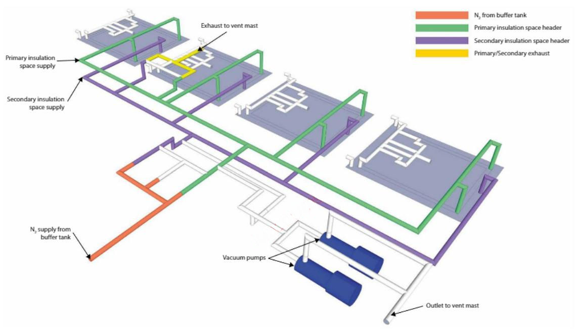
The discharge from the primary insulation space exhaust valves is directed to atmosphere via vent masts that are dedicated to each tank.
The discharge from the secondary insulation space relief valves is directed straight to atmosphere. A manual bypass valve on the primary insulation space relief line is provided for local venting and sweeping of the space, if required.
The containment system manufacturer, the cargo operating manual and company procedures will provide specific instructions for the N2 pressurisation system and the primary and secondary insulation space pressure settings.
Typical settings are:
- primary insulation space – 4 mbar inlet/6 mbar exhaust;
- secondary insulation space – 2 mbar inlet/4 mbar exhaust.
Inerting of Cargo System
Reference: SIGTTO “LNG Shipping Suggested Competency Standards”, Sections:
1 Have an awareness of the procedures for inerting the cargo system.
2 Know and understand the utilisation of cargo tanks:
- procedure for venting to atmosphere via vent;
- procedure for venting to atmosphere via shore;
- correct line up of supply and exhaust valves and pipelines;
- operation of inert gas generator to supply inert gas;
- temperature and dew point requirements for supplied inert gas;
- alarm setpoints.
- principle to be used to change tank atmosphere:
- line up to implement correct principle;
- monitoring procedures and locations:
- which instruments to use;
- correct operation of inlet and exhaust valves;
- interface between atmospheres.
- parameters to determine operation completed:
- oxygen content;
- dew point.
- understanding maximum duration for tanks to have an inerted atmosphere – according to CCS designer’s instructions;
- dangers associated with incorrect inerting procedure;
- use of nitrogen for cargo tank inerting.
3 Know and understand the utilisation of cargo pipelines:
- principles for a plan for inerting pipelines and equipment;
- line up and supply to cargo pipelines;
- apply lines and equipment;
- areas requiring special consideration;
- apply final line and equipment condition regarding O2 and dew point.
Inerting should take place between leaving the dry dock and achieving full plant availability. It may be conducted a number of days before the ship arrives at the load port for gassing up, cooldown and loading. Inerting follows immediately after the “drying” stage and the cargo line-up for inerting is the same as for “drying”.
The inert gas (IG) generator is used to produce IG on board the LNGC with a typical O2 value of 2 % and a dew point of minus 45 °C (-45 °C) or dryer. The cargo tanks, pipelines and associated equipment are, therefore, inerted to a level where combustion cannot take place. Removing the flammability hazard means that, when gassing up, the atmosphere in these spaces will never pass through the flammable range.
In addition to the cargo tanks, the following associated equipment must also be inerted:
- gas heaters;
- LNG cargo vaporiser;
- spray header;
- spray rail;
- cargo discharge lines;
- gas header;
- instrumentation boxes;
- forcing vaporiser;
- LD and HD compressors;
- spray pumps;
- cargo pumps;
- manifolds;
- tank gauging columns;
- fuel gas supply line to the E/R.
A membrane ship will include emergency cargo pump columns.
Inerting can be carried out using N2 but this is generally avoided because of the cost. However, it should be noted that combustion generated IG contains approximately 15 % CO2. The significance of the presence of CO2 is that it will freeze at minus 56 °C (-56 °C) producing a white powder that can block valves, filters and spray nozzles.
Before gassing up and the introduction of LNG vapour, any pipework not purged with IG must be purged with N2.
Checks while purging with IG:
During the inerting procedure, the pressure in the tanks must be kept as low as possible to maximise the “piston effect”. The initial flow should allow gradual filling to the tank bottom. This can be done for the first hour of the operation. Afterwards, the flow should be increased to the maximum.
All sampling points should be checked throughout the operation. If, at an early stage of the inerting operation (i. e. the first 3 hours), a reduced O2 content is observed anywhere except at the bottom of the tank, it will indicate that the piston effect has not been achieved and that the operation will take longer than planned.
At regular intervals, take samples of the discharge from the vapour dome at the top of each tank (this can also be done at intermediate levels) and test for O2 content. Also test at a purge valve at the filling line of one of the tanks being inerted to verify that the O2 content of the IG remains at less than 3 %.
Purge all of the unused sections of pipelines, blind ends, machinery, associated equipment and instrumentation lines as per the cargo operating manual.
When the O2 content sampled from a tank outlet reaches 2 % (dew point < minus 25 °C (-25 °C)), isolate the tank.
In the final stages of inerting, cargo tanks should be pressurised to recommended values. If necessary, the IG plant can be operated for top-up purposes.
Considerations for membrane ships
On LNGCs with membrane containment systems, company policy and manufacturers’ recommendations should be followed regarding the length of time the containment system is under an inert atmosphere.
Ensure that the tank pressure is always 10 mbar greater than the insulation space pressure. Do not allow the tank pressures to exceed 180 mbar above atmospheric pressure. During the inerting procedure, the pressure in the tanks must be kept as low as possible to maximise the “piston effect”.
An essential principle for all membrane type LNGCs is that tank pressures must always be maintained within designed limits while the LNGC is in service. It is the internal tank pressure that keeps the membrane pressed against the underlying load bearing insulation. If this pressure is allowed to fall outside of GTT’s recommended parameters, then membrane fatigue stresses, induced by the LNGC’s motion and vibration, increase dramatically.
Prolonged exposure to fatigue stresses may contribute to a reduction in the life expectancy of the membrane or cause serious membrane damage. On completion of inerting and pressurisation, if the cargo system is tight the IG plant will not need to be run-up for top-up purposes.
Inerting and gassing up of new build LNGCs
During gas trials, the LNGC will proceed from the shipyard to an LNG receiving terminal, where a parcel of LNG will be loaded and gas trials conducted alongside and at sea.
On LNGC newbuilds, or after dry-dock, there is the option of inerting the cargo system with N2 supplied from ashore, rather than IG, as this will remove the need for gassing up at the load port. This will be a commercial rather than an operational decision.
Operational description – inerting cargo tanks (prior to gassing up)
As with the drying process, the flow loop directs IG from the IG plant to the liquid header and into the cargo tanks via the tank branch valves and the filling lines. Purged air from the tanks is exhausted to the vapour header via the tank dome vapour valves and released to atmosphere via the forward vent mast.
The procedure is as follows:
- start the IG generator to produce IG discharging to the atmosphere;
- when the O2 content is < 1 % by volume and the dew point from the IG plant is minus 45 °C (-45 °C), open the valve to deck;
- flow is now established through the filling line of each cargo tank and dry air is vented via the vent mast;
- monitor the O2 content of each tank by taking a reading with a portable gas detector at the liquid and vapour domes and at the sample points;
- purge through the sample valves and lines on the main cargo pumps. emergency pump discharge, float gauge column. radar still pipe, etc.;
- purge through the spray header and spray pumps;
- the compressors, vaporisers, heaters and manifolds must be purged through, with a reading taken at the sample points to ensure that all parts of the system have been inerted;
- where there are blank flanges, these should be slackened off to allow the section of line to be properly inerted;
- when the O2 content measured in the cargo tanks is < 1 % by volume, filling and vapour valves of the tank are closed (change over IG flow to the atmosphere);
- when all the tanks are inerted, stop the IG plant;
- close the supply valve to the liquid header and close the venting system at the vent mast;
- the spool piece connecting the IG line with the liquid header line should be removed and blanks fined.