This article covers the complete cycle of ship loading and discharging operations. Consolidating text is written here to help personnel evaluate how different equipment and procedures fit into operational practice. Every ship will have its own detailed operational procedures. What can be done on one ship may not be possible or even desirable on another. However, the basic principles of cargo handling for liquefied gas remain the some for all gas carriers.
- Sequence of Operations
- Initial Preparations
- Tank inspection
- Drying – cargo system
- Drying – hold spaces and interbarrier spaces
- Changing Tank Atmospheres
- Principles of atmosphere changing
- Displacement
- Dilution
- Inerting – Before Loading
- Inerting pipelines and cargo machinery
- Tank preparation prior to loading ammonia
- Gassing-Up
- Gassing-up at sea using liquid from tanks
- Gassing-up alongside
- Cool-down
- Refrigerated LPG cargoes
- LNG
- Semi-pressurised/semi-refrigerated ships
- Loading
- Preliminary procedures
- Trim, stability and stress
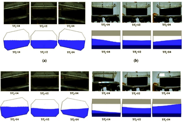
- Sloshing
- Management of tank pressure during loading
- Commencement of loading
- Operation of the reliquefaction plant during bulk loading of LPG
- Operation of the reliquefaction plant during bulk loading of LNG
- Cargo tank loading limits
When a gas carrier first comes alongside a berth to carry out cargo handling operations, the preliminary procedures as outlined in article “Ship/shore interface for safe loading and unloading of LNG/LPGShip to shore of other gases by LNG/LPG carriers, rules and equipment” are followed. Prior to cargo operations commencing, cargo handling plans for the intended operation are developed, discussed and agreed between the ship and the terminal. These written plans will, amongst other matters, detail cargo flow rates, tank sequences, specific responsibility for various operations, communications, general emergency procedures. A more detailed list of items that may need to be discussed can be found in article “Ship/shore interface for safe loading and unloading of LNG/LPGDiscussions Prior to Cargo Transfer“.
Sequence of Operations
All gas carriers follow a broadly similar pattern of cargo operations, although liquefied natural gas (LNG) carriers are dedicated to carrying a single grade while liquefied petroleum gas (LPG) carriers are typically capable of carrying different grades on each voyage.
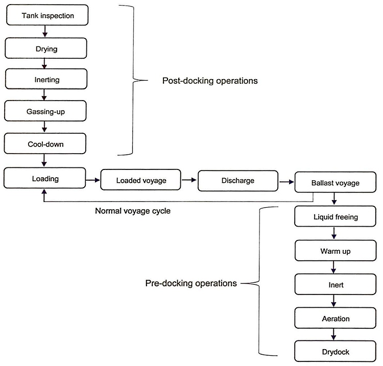
The following sections illustrate a typical voyage cycle for an LNG carrier and an LPG carrier. However, it should be noted that specific voyage orders may modify this generic view.
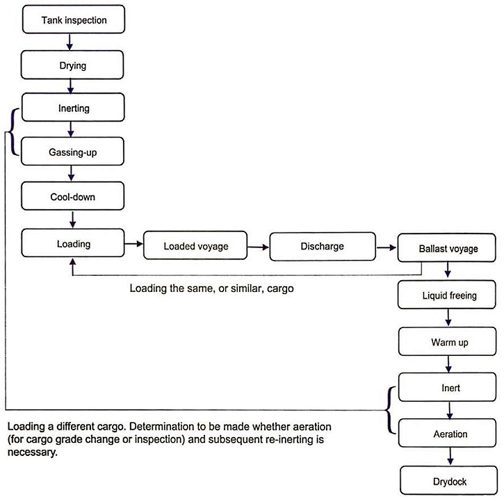
In each case they start with a ship that has just left the drydock/shipyard.
Initial Preparations
Tank inspection
While cargo tank inspection is important on any ship type, it is particularly important on gas carriers due to the number of operations, time and cost involved in taking a cold tank out of service and preparing it for entry. When inspecting the tank the following will typically be carefully checked:
General cleanliness
That there are no rags, dirt or debris left in the tank as these may block or damage the cargo pumps and/or the cargo containment system itself, especially in the case of membrane tanks.
Free water
Any free water (pools of water) that has formed in the tank while it was open will need to be removed to prevent problems with ice or hydrates when cargo is loaded. You would not normally find free water in LNG tanks during a drydock due to the protective covers that are usually fitted over the tank access hatches. However, it is more likely to be found in LPG ships, where the use of such covers is less common.
Fittings and connections
That all fittings and connections inside the tank are properly secured with particular attention to any items that may have been overhauled.
Drying – cargo system
Drying of the cargo system in any refrigerated ship is a necessary precursor to loading. Note that the cargo containment system includes cargo pipelines and machinery in addition to the cargo tanks. Drying means that all free water and water vapour in the atmosphere should be removed. Free water is best removed from the tank prior to the tank inspection. Although it is possible to remove it during the tank drying operation, doing so will extend the duration of the operation.
If the cargo system is not adequately dried, residual moisture can cause problems with icing and hydrate formation when the tanks are cooled down. To illustrate the potential problem, air at 30 °C, at atmospheric pressure and 100 % humidity, can contain 30,4 g/m3 of water. This would equate to approximately 30 litres of water per 1 000 m3 of air. For a large LPG carrier, of 80 000 m3 capacity, it would be equal to approximately 2 400 litres of water in the cargo containment system.
The objective of drying is to lower the dew point temperature (see article “Gas laws, thermodynamic principles and reliquefactionThe bubble point’ and “dew point” of mixtures“) in the tank to a temperature below that at which the cargo vapour will be introduced during the gassing-up operation. A typical value to achieve would be a dew point temperature of around minus 20 °C (-20 °C). Malfunction of cargo pumps, valves and spray nozzles due to ice or hydrate formation is often the result of an inadequately dried cargo system. While the addition of antifreeze may be possible at pump suctions and other parts of the cargo system, it is not generally considered a substitute for thorough drying. Antifreeze is not permitted to be used with all cargoes and, where it is, it may not be effective at the carriage temperature for the cargo being carried.
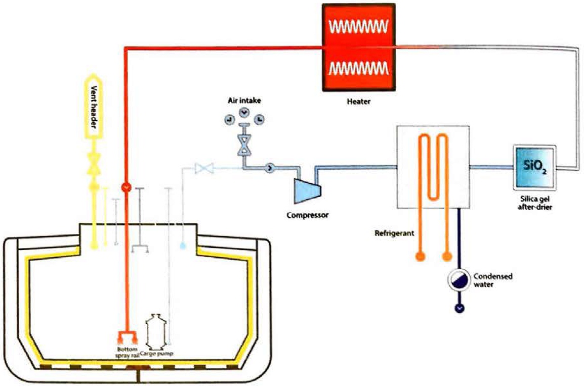
On board air drying with an inert gas generator
Inert gas generators are usually capable of operation in “dry air” mode. In this mode the plant operates without combustion and the blowers send air to the cooler and adsorption drying towers to deliver air with a low dew point, typically in the region of minus 40 °C (-40 °C), to the tanks. (See article “Liquefied Petroleum Gas Reliquefaction Plant and Boil-Off ControlInert gas generators” for a description of the inert gas generator and associated cooler and adsorption drier). The dry air enters the bottom of the tank and any moist air is exhausted from the top of the tank. While in the tank it will absorb any moisture that may be present on the tank structure.
On board drying and inerting with an inert gas generator
Drying can be accomplished at the same time as the inerting operation. The effectiveness of this method depends on the dew point temperature that the inert gas generator can achieve, the amount of moisture in the tank and acceptance of the need to continue to produce inert gas to further lower the dew point in the tank after inerting of the tank has been completed (in cases where the dew point is still too high at the end of the inerting operation). This can add significant cost because of the cost of producing inert gas throughout the operation.
Drying using inert gas from shore
This is similar to the method above except that the inert gas is supplied from shore rather than from the ship’s inert gas generator. This may be required on gas carriers that are not fitted with on inert gas generator. Typically, the inert gas supplied from shore is nitrogen.
Drying – hold spaces and interbarrier spaces
Hold spaces, interbarrier spaces on membrane tanks and annular spaces on spherical tanks will also be dried. These spaces will be exposed to low temperatures and, in the case of interbarrier and annular spaces on gas carriers carrying refrigerated cargoes, the temperatures will be very low. If the interbarrier and annular spaces have any moisture in them when the tanks are cooled down, the water vapour will condense into the insulation and then expand on freezing, which may damage the insulation and reduce its performance. Hold spaces are dried to protect the outer part of the insulation and to prevent the condensation that can lead to corrosion problems on the steel work.
(Note: The hold spaces on LPG carriers fitted with independent Type A tanks must be inerted when carrying flammable cargoes, as is required by the IGC Code)
These spaces are much smaller in volume than the cargo tanks and are normally dried by the process of inerting. The IGC Code requires that interbarrier and hold spaces associated with cargo containment systems for flammable gases requiring full secondary barriers be inerted. This is achieved using either inert gas or nitrogen. The IGC Code allows the interbarrier and hold spaces for cargo containment systems for certain flammable gases requiring only a partial secondary barrier, such as Moss type LNG carriers, to be maintained in a dry condition and pressurised with dry air, provided the capability exists to quickly detect a leak and inert the hold space before a dangerous condition can develop. For non-flammable gases, the IGC Code allows that interbarrier and hold spaces may be maintained simply with dry air.
Changing Tank Atmospheres
Principles of atmosphere changing
Tank atmosphere changing is required for several cargo operations, such as inerting, gassing up, purging and aeration of the tank.
On LPG carriers grade changes between, for example, LPG and ammonia will require an atmosphere change. The two methods of changing atmosphere are displacement and dilution.
Displacement
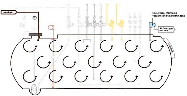
Displacement, also known as the piston effect, relies on stratification of the cargo tank atmosphere based on the difference in vapour densities between the gas entering the tank and the gas already in the tank. The heavier gas is always beneath the lighter gas. This means the lighter gas may be introduced above a heavier gas, or a heavier gas introduced below a lighter one. Figure 6 shows an example of stratification using air and inert gas as the relative gases in a cargo tank.
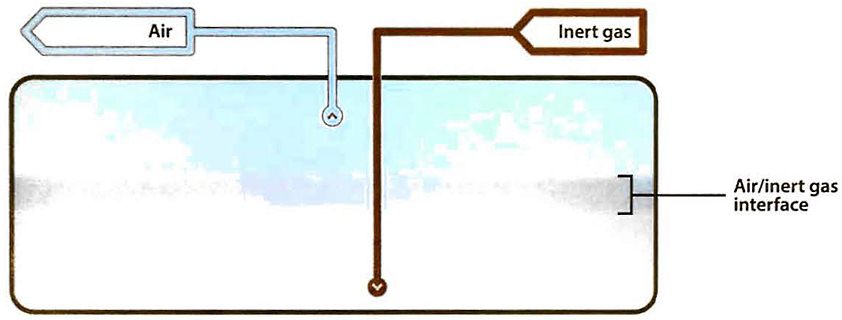
Table “Properties of liquefied gasesPhysical properties of gases” shows the relative vapour densities of gases to air, but does not include inert gas. Due to the high proportion of CO2 n inert gas, (approximately 14 to 16 % volume compared with 0,04 % volume in air), inert gas is considered to be slightly heavier than air. The table assumes all gases are at the same temperature and this will be broadly true of most atmosphere changing operations onboard, which are generally conducted with all gases at ambient temperature. If one gas is considerably warmer or colder than another, consideration will usually need to be given to the effect this has on the density of the gas.
The displacement method may not be as effective as other methods in certain tank shapes due to the turbulence created in the tank when the gas is introduced.
To minimise turbulence the inlet velocity into the tank will typically be as low as possible. When changing the atmosphere in all the cargo tanks the easiest way to achieve this is to do all the tanks at the same time, sometimes referred to as “in parallel“.
If perfect stratification could be achieved, with no mixing between the gases, then a single tank volume would be sufficient to change the atmosphere. In practice, some mixing will occur and the minimum quantity required to change a tank atmosphere by displacement is usually considered in the range of 1,2 to 1,7 tank volumes.
The figure will vary depending on the relative densities of the gases, the amount of turbulence in the tank, the shape of the tank and the pipeline configurations in the tank.
Key advantages of this method are that it requires the smallest quantity of gas to change the atmosphere. It achieves a final tank atmosphere close to that of the gas that was introduced and, for a large part of the operation, the only gas being pushed out by piston effect is the one being replaced. Only in the final stage of the operation is there any trace of the gas that is being introduced to the tank, ie during gassing up operations, that then needs to be vented, a fact that has safety, environmental and commercial impacts on the operation.
Displacement in series
In LPG carriers the displacement method can sometimes be adjusted so that, rather than conditioning all the tanks together “in parallel“, the gas is introduced into one tank and the outlet from the first tank goes to the inlet of the next tank (rather than being directly vented to atmosphere from the first). Only the outlet from the last tank deals with the management of the gas. This is referred to as displacement “in series“, or “cascading“.
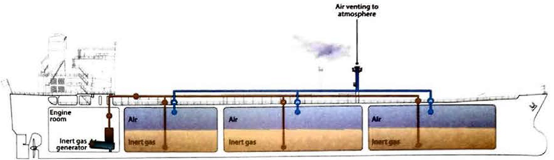
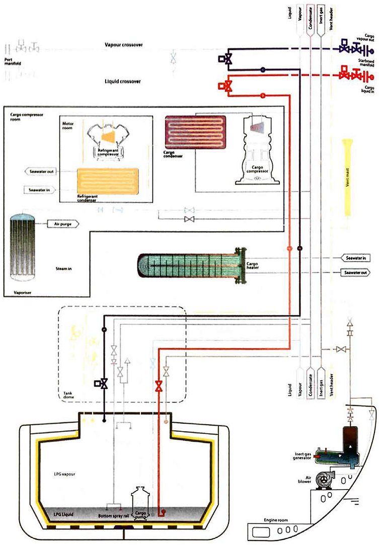
Figure 8 shows a ship that has carried LPG inerting her tanks, with inert gas that is lighter being introduced to the top of the tank and the LPG vapour that is heavier being pushed out of the pipe inlet near the tank bottom.
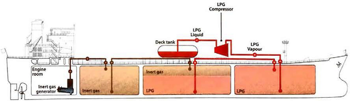
Note that Figure 8 also shows cargo “scavenging“, which is the practice where cargo vapour can be captured and recondensed to a deck storage tank. Venting to the atmosphere only occurs at the end of the inerting process.
The advantages of this system are:
- Since there is only one interface there is less venting of the gas being introduced;
- less cargo vapour is required to gas-up the tanks;
- only the last tank will have any trace of the gas being removed;
- the content of the previous tanks will be 100 % of the gas being introduced.
The disadvantages of this system are:
- There is usually some preparation time, ie making connections between pipelines, before the operation can commence;
- due to the number of crossovers and pipelines to be used, the operation usually takes longer than displacing in parallel.
Dilution
When changing the atmosphere in a tank by the dilution method the incoming gas mixes, through turbulence, with the gas already in the tank. To maximise the turbulence the input velocity of the gas will be as high as possible and, therefore, it is normal for only one or two tanks to be done at a time. The dilution method can be carried out in several different ways.
Dilution by repeated pressurisation
In the case of Type C tanks, atmosphere changing by dilution can be achieved through repeated pressurisation. In this case the gas is pressurised into the tank using a cargo compressor. This is followed by a release of the compressed gases. Each repetition brings the tank nearer to the required gas concentration. It has been found that quicker results can be achieved by more numerous repetitions, each at low pressurisation, than by fewer repetitions at higher pressurisation.
Dilution by repeated vacuum
Type C tanks are usually capable of operating under considerable vacuum and, depending on tank design, vacuum breaking valves are set to permit vacuums in the range from 30 % up to 70 %. Atmosphere changing by successive dilutions may be carried out by repeatedly drawing a vacuum on the tank. This is achieved by using the cargo compressor and then breaking the vacuum with the gas to be introduced.
Continuous dilution
Atmosphere changing by dilution can be carried out as a continuous process. This is the only diluting process available for atmospheric tanks, which have very small over-pressure or vacuum capabilities. For a true dilution process, (rather than one aiming at displacement) it is relatively unimportant where the gas inlet or the tank outlet are located, provided that good mixing is achieved. It is usually satisfactory to introduce the gas at high speed through the vapour connection and to discharge the gas mixture via the bottom loading lines.
When using the continuous dilution method on ships with Type C tanks, increased gas flow (and 50 better mixing and reduced overall time) may be achieved by maintaining the tank under vacuum. This is typically accomplished by drawing the vented gas through the cargo vapour compressor.
Caution should be taken not to use the vacuum-assist dilution method to remove flammable vapours from tanks due to the risk of air ingress, which could result in the development of a flammable atmosphere.
Inerting – Before Loading
Inerting of cargo tanks, cargo machinery and pipelines is primarily undertaken to ensure a non-flammable condition throughout the cargo system during subsequent gassing-up with cargo vapour (see article “Properties of liquefied gasesSuppression of Flammability“).
Current industry practice is that the oxygen concentration should be reduced to a maximum of 5 % by volume, although values of 2 % by volume are usually achieved through a combination of the low oxygen content inert gas produced by the inert gas generator, the methods of tank atmosphere changing employed and the arrangement of the pipelines in the tanks.
Inerting by displacement
As inert gas generated by an onboard generator is slightly heavier than air, the inert gas is introduced from the bottom of the tank via the loading line and the air is exhausted from the top of the tank via the vapour line and then to the vent mast. Nitrogen is lighter than air, so the piping connections would need to be reversed to introduce the nitrogen into the top of the tank via the vapour line, with the air exhausted from the bottom of the tank via the loading line and then to the vent mast. If all cargo tanks are to be inerted, the process of inerting all tanks in parallel is generally considered to be the most effective and efficient method, as it reduces both the inlet velocity to each tank and the overall resistance to flow through a greater number of pipelines.
Inerting by dilution
This can be achieved by any of the three methods described in point “Dilution” above. When diluting by repeated pressurisation, the inert gas is pressurised into the tank using a cargo compressor and air is vented to atmosphere. The cycle of pressurisation and venting is repeated several times and the lower the oxygen content of the inert gas the lower the number of cycles required to bring the atmosphere to less than 5 % oxygen by volume.
Inerting by repeated vacuum is achieved through the use of a cargo compressor and then breaking the vacuum with inert gas. If, for instance, a 50 % vacuum can be drown then, on each vacuum cycle, half the oxygen content of the tank is removed. Some of the withdrawn oxygen will be replaced by the oxygen present in the inert gas.
Caution should be taken not to use the vacuum-assist dilution method to remove flammable vapours from tanks due to the risk of air ingress, which could result in a flammable atmosphere.
Of all the dilution processes, this method can be the most economical as only the minimum quantity of inert gas is used to achieve the desired inerting level. The overall time taken, however, may be longer than with the pressurisation method because of reduced compressor capacity when working on vacuum and a slow rate of vacuum-breaking due to limited output of the inert gas generator.
Inerting pipelines and cargo machinery
The IGC Code requires that cargo tanks and pipelines are inerted so that at no point will there be any possibility of a flammable atmosphere occurring. The pipelines and cargo machinery can be inerted during or after the inerting of the cargo tanks. Careful planning is required to ensure that no sections of line or dead ends are omitted.
The pipelines on LNG carriers are sometimes inerted with nitrogen from the ship’s nitrogen generator. This is because, unlike nitrogen, inert gas contains CO2 which will freeze during cargo system cool-down and possibly block filters and spray nozzles. To avoid any problems with blocked filters, etc., the liquid header, spray header and vaporisers are inerted with nitrogen prior to gassing up the cargo tanks.
Generally, if the gas carrier is at sea, the pipelines are blown out to atmosphere via a vent mast, the end of a line or a manifold.
If the vent mast is not used to exhaust the inert gas, it is prudent to evaluate the risks that would be involved in an alternative arrangement.
Tank preparation prior to loading ammonia
The usual practice, as part of the gassing-up process, is to introduce ammonia vapour into tanks that contain dry air. However, there may be occasions where the charterer requires the tanks to be inerted with nitrogen from shore when grade changing from LPG to ammonia.
In order to minimise the risk of ammonia stress corrosion cracking, levels of oxygen in the dry air to as low as 0,9 % volume may be required prior to the introduction of ammonia into the cargo tanks. The level depends on the carriage temperature of the ammonia cargo. The IGC Code provides guidance on oxygen content (percent volume) as a function of the carriage temperature, and this should be incorporated into the ship’s cargo operations manual.
Gassing-Up
On an LPG carrier with a reliquefaction plant, neither nitrogen nor carbon dioxide, which are the main constituents of inert gas, can be condensed by the plant. This is because, at cargo temperatures, both gases will be above their critical temperature and, therefore, incondensible. Removal of inert gas from the cargo tank is therefore necessary.
Removal of the inert gas is achieved by gassing-up. This can be accomplished using warm vapour from the cargo to be loaded and venting the inert gas.
Venting can either be to the atmosphere or it can be returned to the terminal if the terminal is designed o r configured to receive such vapours.
On LPG ships, when changing grade without any intervening inerting, it may first be necessary to remove the vapour of the previous cargo by using the vapour of the cargo to be loaded. This may be done when changing a tank from propane to butane or vice versa.
It will be interesting: Liquefied Natural Gas Tank Protection
The basic principles described in point “Changing Tank Atmospheres” above in respect of methods of changing atmospheres apply equally to the operation of gassing-up. When gassing-up there is usually a greater density difference between cargo vapours and the inert gas, see Table “Properties of liquefied gasesPhysical properties of gases“, than is the case when inerting from air.
In most cases cargo vapour will be created in the ship’s vaporiser from liquid supplied either from ashore, another cargo tank or a deck storage tank. The outlet temperature from the vaporiser will typically be close to the ambient temperature in the cargo tank. To improve stratification, it may be beneficial to have lower temperature cargo vapours displacing the inert gas/nitrogen. However, the outlet temperature from the vaporiser will always need to be greater than the dew point temperature of the inert gas in the cargo tank to prevent condensation and subsequent freezing of any water vapour present in the inert gas. See article “Cargo equipment for gas carriers carrying LNG/LPGCargo Vaporisers” for further information on the operation of cargo vaporisers.
Gassing-up at sea using liquid from tanks
Gassing-up at sea is a procedure that may be carried out when cargo is available onboard. Fully-refrigerated and semi-pressurised LPG ships are often equipped with deck tanks that have a compatible cargo in storage, although gassing-up may also be carried out when there is sufficient cargo in another tank. Either vapour or liquid can be taken from the storage tank into the cargo tanks.
Liquid from the storage tank is vaporised using available means on board and introduced gradually into the top or bottom of the cargo tank, depending on the relative vapour density, to displace the existing inert gas, or vapour, to other tanks or to the vent riser.
On LPG carriers, gassing-up in series/cascading is generally considered to be the most efficient method if the quantity of cargo available is limited and time is available. It has the added advantage of leaving only part of on inert gas/cargo vapour interface in the last tank, all the others being 100 % cargo vapour, minimising the venting of hydrocarbon gases. Reducing the incondensible gases in the system will usually be an advantage when the reliquefaction plant is operated.
Gassing-up alongside
Such operations require careful planning and cooperation and making full use of terminal facilities. A proper operational plan is to be prepared, taking into full account the cargo system design parameters and procedures contained in the ship and terminal cargo operations manuals. If a deck tank is available, this will be a key part of the process. The plan will usually be reviewed as port of the pre-transfer meeting (see article “Ship/shore interface for safe loading and unloading of LNG/LPGDiscussions Prior to Cargo Transfer“).
Gassing-up operations that take place alongside use cargo supplied from the shore, which is normally vaporised in either the ship’s vaporiser, if fitted, or shore terminal vaporisers. At certain terminals, facilities exist to allow the entire operation to be carried out alongside. This is because the venting of hydrocarbon vapours alongside a jetty may present a hazard and is, therefore, prohibited by most terminals and port authorities.
Before commencing gassing-up operations alongside, the terminal will normally sample tank atmospheres to check that the oxygen is less than 5 % volume (or is at the much lower concentrations required for chemical gases such as VCM).
Gassing-up of LPG carriers alongside
Before a ship arrives in port with her tanks inerted, the following points should be amongst those considered:
- Is a vapour return facility to a flare available?
- Is venting allowed alongside? If so, what is permissible?
- Is liquid or vapour provided from the terminal for gassing-up?
- Will only one tank be gassed-up and cooled down initially from the shore?
- How much liquid must be taken on board to gas-up and cool-down the remaining tanks?
- Where can the full gassing-up operation be carried out?
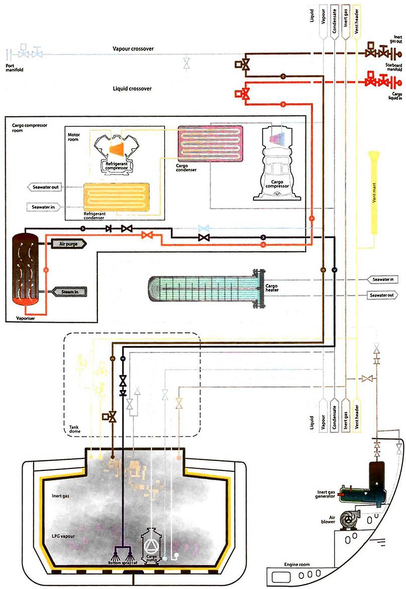
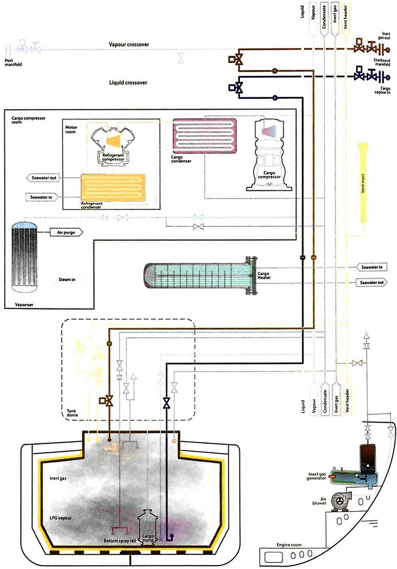
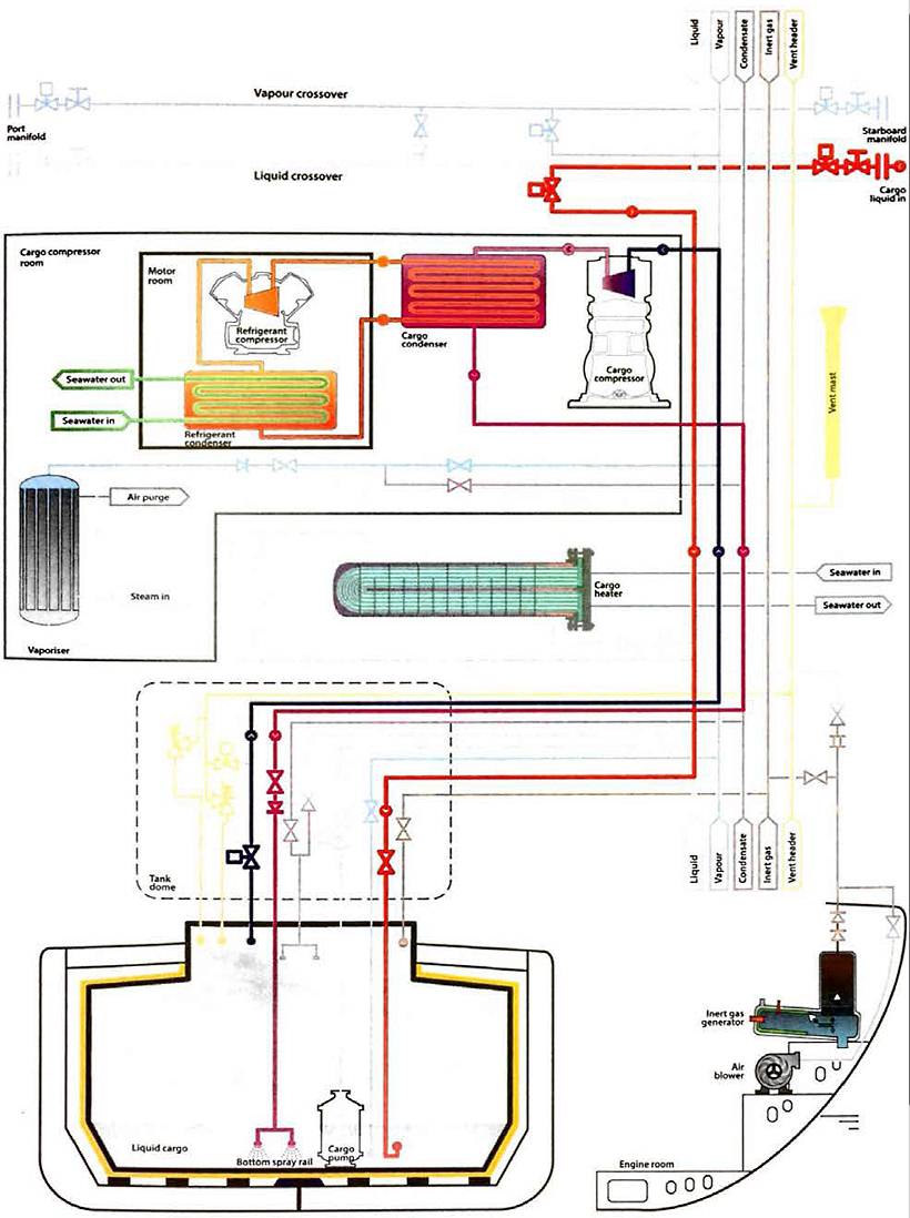
Where a terminal supplies a liquid for gassing-up it is prudent for it to be loaded at a carefully controlled rate and passed through the ship’s vaporiser, if fitted. If vapour is supplied, this can be introduced into the tank at the top or bottom, depending on the vapour density. Figures 11 and 12 show typical gassing-up operations using liquid from shore and vapour from shore.
When a ship arrives alongside, with tanks containing a cargo vapour that requires to be displaced, or, more accurately, replaced with the vapour of a different grade, the terminal will normally provide a vapour return line. The vapours taken to the shore will be recovered ashore or flared until the desired vapour quality is achieved in the tanks. At this point cool-down can begin.
Some LPG vapour recovery systems can use the energy obtained from vaporising liquid nitrogen to reliquefy the cargo vapour returned from the ship, either during gassing-up operations or during inerting operations (see point “Features of cargo delivery LNG/LPG carriersGas-Freeing” below), and avoid any venting of hydrocarbon gases. Skid mounted units receive liquid nitrogen from a truck, vaporise it for delivery to the ship and, at the same time, reliquefy the return cargo vapour for storage and further usage.
If facilities such as a vapour return line or vapour recovery system are not available for the ship to gas-up alongside, it is common practice for the ship to prepare one cargo tank and take sufficient liquid to complete the operation elsewhere. The ship then leaves the berth for a designated anchorage or proceeds to sea. The ship returns to the berth after having gassed-up and cooled-down all of her cargo tanks.
Gassing-up of LNG carriers alongside
For LNG carriers it is normal practice to conduct the entire operation alongside as LNG terminals or, configured to receive cargo vapour from the ship and to flare the inert gas/cargo vapour mixture. LNG carriers will use the displacement method of atmosphere changing.
Some terminals will not permit any venting to atmosphere, in which case all the inert gas and cargo vapour from the tanks must be returned to the shore. In this case either the vapour can free flow to the shore, if there is sufficient flow, or the ship’s compressor can be used to handle the inert gas
being displaced from the cargo tanks.
Some terminals, while prohibiting the venting of cargo vapours, permit the venting to atmosphere of inert gas. In such cases it is common for the LNG carrier to vent inert gas from the forward vent most until a hydrocarbon concentration of 5% by volume is detected. From this point onwards all vapour will be returned to the shore, either by free flow or with the high duty compressor.
Gassing-up of pipelines and machinery
Once the cargo tanks have been gassed-up the remaining cargo pipelines and machinery will also be gassed-up. Failure to do this will trap inert gas in the cargo system and cause the problems described in article “Properties of liquefied gasesThe chemical compatibility of cargoes with inert gas or nitrogen“. Gassing-up of the remaining pipelines and machinery can be treated as a separate operation once the tanks are gassed-up.
Alternatively, the lines can be gassed-up at the same time as the cargo tanks are being gassed-up, which requires careful planning.
As a general principle, the lines will be vented to atmosphere and not back to the tanks, which would introduce inert gas back into the tank. This may not be too difficult if the ship is conducting the operation at sea, but may be difficult to achieve with the ship alongside.
Cool-down
The primary purpose of cool-down is to avoid thermal stress on the tanks. A secondary benefit is the avoidance of the excessive tank pressures that could occur if cold liquid was introduced into o warm tank. The rate at which a tank can be cooled down can usually be confirmed from the ship’s operating manual. In some cases a maximum temperature difference between the top and bottom of the tank may also be specified. The lower the temperature of the cargo to be loaded, the more important the cool-down procedure becomes.
LNG carriers have an additional requirement during cool-down of managing the nitrogen pressure in the interbarrier spaces on membrane type LNG carriers and in the annular space on Moss and SPB type LNG carriers.
Refrigerated LPG cargoes
The normal cool-down procedure takes the following form. Cargo liquid from shore (or from deck storage) is gradually introduced into the tanks through either spray lines or via the cargo loading lines. The vapours produced by rapid evaporation may be taken ashore or handled in the ship’s reliquefaction plant. Additional liquid is then introduced at a rate that depends on tank pressures and temperatures. If the vapour boil-off is being handled in the ship’s reliquefaction plant, difficulties may be experienced with incondensibles remaining from the inert gas. A close watch will usually be kept on compressor discharge temperatures and the incondensible gases will usually be vented from the top of the condenser as required.
As the cargo containment system cools down, the thermal contraction of the tank, combined with the drop in temperature around it, tends to cause a pressure drop in the adjoining hold space. Pressure control systems supplying air or inert gas will usually maintain these spaces at suitable pressures, but a watch will usually be kept on appropriate instruments as the cool-down proceeds.
Cool-down will continue until boil-off eases and liquid begins to form in the bottom of the cargo tanks. This can be seen from temperature sensors. At this stage, for fully-refrigerated LPG for example, the pool of liquid formed will be at approximately minus 40 °C (-40 °C) while the top of the tank may still be at minus 14 °C (-14 °C), giving a temperature difference of 26 °C. The actual temperature difference depends on the size of the cargo tank and the position of the spray nozzles.
Difficulties that may occur during cool-down can be the result of inadequate gassing-up (too much inert gas remaining) or from inadequate drying. In this latter case, ice or hydrates may form and ice-up valves and pump shafts. In such cases, and subject to the approval of the charterer, antifreeze can be added, provided, for example, that it is compatible with the cargo or that the addition will not damage the electrical insulation of a submerged cargo pump. Throughout the cool-down, deepwell pump shafts should be turned frequently by hand to prevent the pumps from freezing up.
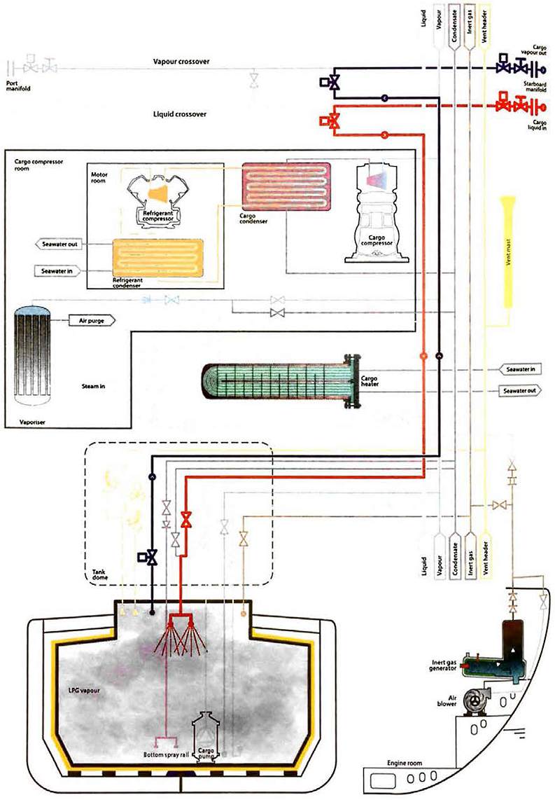
Figure 13 shows the pipeline arrangement for tank cool-down using liquid supplied from the shore.
LNG
Liquid is taken from the shore and crossed over into the spray lines fitted in each tank. The vapours produced from spraying are returned to the shore via the LNG carrier’s high duty compressors. (This would still be the case on an LNG carrier fitted with a reliquefaction plant, since the plant is not normally rated to deal with this volume of vapour and is not likely to be fully operational if the LNG carrier has only just completed the gassing-up operation).
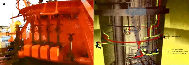
a – connections on a Moss tank dome; b – in tower in a Moss tank dome
On Moss type ships the rate of cool-down is critical for the management of stress in the equatorial ring, where the skirt attaches to the tank, and so the readings from the temperature sensors fitted to the skirt will be compared with the cool-down table in the LNG carrier’s operating manual. Nitrogen pressure in the annular space will be monitored as it cools with the tank and the flow of nitrogen to the annular space will be increased to compensate for the falling pressure. The cargo manual will specify the temperature to which the equator must be cooled before loading can begin, which is typically in the range minus 110 °C (-110 °C) to minus 124 °C (-124 °C).
For membrane type LNG carriers the rate of cool-down of the membrane is not normally as critical. However, the pressure in the tank and the pressure of the nitrogen in the interbarrier spaces will still be closely monitored as they typically limit the rate of cool-down. As with the annular space in the Moss type ship, the nitrogen pressure will fall as the membrane cools. The flow of nitrogen will usually be increased to maintain the required pressure. This puts a high demand on the LNG carrier’s nitrogen generators, both of which will normally be in use for this operation. The cargo manual will specify the temperature the tank must be cooled down to before the tank can be considered ready for loading but, typically, cool-down is considered complete when the temperature sensors in each tank indicate an average temperature over the whole tank of minus 130 °C (-130 °C).
The ship’s designer and builder will include the information in the ship’s operating manuals, but for general reference, the representative cool-down time is normally 24 to 36 hours for a Moss type LNG carrier and normally 10 to 12 hours for a membrane type LNG carrier.
Semi-pressurised/semi-refrigerated ships
Most semi-pressurised/semi-refrigerated (SP/SR) ships (see article “Liquefied Gas Carrier TypesSemi-refrigerated ships“) have cargo tanks constructed of steels suitable for the minimum temperature of fully-refrigerated cargoes. For these ship types cool-down of the tanks will be the same as for refrigerated LPG carriers, which is described in point “Refrigerated LPG cargoes”.
In cases where the tank steel is not rated for the fully-refrigerated temperature of the cargo, it is prudent to take care to avoid subjecting the steel to lower temperatures. The pressure within the cargo tank will be maintained at a level that is at least equal to the saturated vapour pressure (SVP) corresponding to the minimum allowable steel temperature. This can be done by passing the liquid through the cargo vaporiser and introducing vapour into the tank with the cargo compressor. Alternatively, vapour can be provided from the shore.
Loading
Preliminary procedures
Before loading operations begin, the pre-operational ship/shore procedures will be thoroughly discussed and carried out. Appropriate information exchange is required and the relevant ports of the “Ship/shore interface for safe loading and unloading of LNG/LPGShip/Shore Safety Checklist” (Section 26 of Reference 2.4) will be completed. Particular attention will usually be paid to:
- Setting cargo tank relief valves and high pressure alarms;
- remotely operated valves;
- reliquefaction equipment;
- gas detection and ventilation systems (especially for changes of cargoes with different densities, see article “Liquefied Petroleum Gas Reliquefaction Plant and Boil-Off ControlGas detection system“);
- alarms and controls;
- process for adding inhibitors, if applicable;
- topping off procedures;
- responsibility for stoppage of transfer;
- maximum loading rate.
This will all be carried out taking into account restrictions at the ship/shore interface.
The terminal will normally provide the necessary information on the cargo, including inhibitor certificates where inhibited cargoes are loaded. Any other special precautions for specific cargoes should be made known to ship personnel. This may include the lower compressor discharge temperatures required for some chemical gas cargoes. Where fitted, variable setting pressure relief valves (PRVs), high tank pressure alarms and gas detection sample valves should be correctly set.
Deballasting can take place simultaneously with loading, subject to local regulations. Ship stability and stress are usually considered to be of primary importance during loading.
When handling low cargo temperatures, the MLAs and ship’s pipelines will require cooling. This is normally achieved by the terminal supplying liquid that is passed through the ship’s lines until they are sufficiently cooled. Interbarrier and annular space nitrogen pressures are normally raised slightly above their normal operating pressures and both nitrogen generators are put online in anticipation of the increased nitrogen demand that occurs when the temperature and pressure drops in these spaces.
Prior to starting to load, the emergency shutdown (ESD) system will be tested. The IGC Code requires that cargo ESD and alarm systems involved in cargo transfer should be tested and checked before cargo transfer operations begin.
It is usually preferred to connect ship and shore ESD systems, if suitable connections exist.
Physical inspection of the ship/shore electric or fibre optic cables and/or pneumatic hoses will normally be completed as part of the pre-arrival checks.
Post-arrival testing will normally include a functional test of the link, after connection but before commencement of cargo operations. This involves opening the manifold valves and proving they close by tripping the link (warm ESD test). It is common practice to demonstrate proper valve movement in the cold condition by manipulating the valve on completion of MLA cool-down. It is not essential to combine this cold valve test with a second ESD link test.
For further details see “ESD Arrangements & Linked Ship/Shore Systems for Liquefied Gas Carriers” (Reference 2.16).
Trim, stability and stress
The cargo plan should allow for distribution within the ship to achieve acceptable structural stress and the required ship trim to meet safe stability conditions when at sea. For these purposes the weight of the cargo in each tank will need to be known. For ship stability purposes, the weight in question is the true weight in air (see article “Measurement and calculation of cargo on gas carriersGeneral – density in air and density in a vacuum“).
IMO regulations require that all gas carriers are provided with stability data, including worked examples, showing various loading conditions along with information on consumables carried, such as fresh water, spare parts and bunkers. Additionally, as part of the requirements to obtain a Certificate of Fitness, the IGC Code requires that, in specified damaged conditions, the ship will meet certain survivability requirements specified in the IGC Code. It is, therefore, essential that all relevant guidance concerning the filling of cargo tanks is observed.
Some cargoes, such as VCM, have a high density and the weight of cargo carried in a tank may be restricted in such cases.
Sloshing
Large prismatic cargo tanks, due to their width and shape, may suffer from substantial sloshing of cargo in heavy pitching or rolling conditions. Such tanks, and particularly membrane type tanks that have no centreline swash bulkheads, may have restricted filling levels (ie minimum upper and maximum lower) to avoid damage to tank structures or internal fittings. The LNG carrier’s cargo manual will set out the prohibited filling levels.
If an unusual cargo distribution is requested, and if this involves cargo tanks only being part-filled, then it is usual for the ship’s Master to seek further guidance from the ship operator. In such cases it is sometimes necessary for the ship operator to seek confirmation from the ship’s Classification Society before loading can start.
Management of tank pressure during loading
Tank pressure management on fully-refrigerated LPG carriers
At the start of loading there is potential to create a lot of vapour and, on refrigerated LPG carriers where tank PRVs are typically set in the order of 250 mbar, this can be a critical period.
Factors that will affect the amount of vapour produced at the start of loading will include:
- The temperature of the tank compared to the temperature of the cargo;
- initial cargo temperature, (can be warmer at the start of the operation);
- splashing of liquid exiting the loading line until the loading line is submerged;
- surface area of the liquid in the bottom of the tank. This is much larger on a prismatic-shaped tank than a spherical tank and, as evaporation is related to surface area, it can have a significant effect on the amount of vapour generated.
During the loading operation the management of the tank pressure is normally achieved by using:
- Vapour return to the shore with a compressor;
- the ship’s reliquefaction plant for liquid return to the ship’s tanks;
- spraying of liquid in the vapour space on pressurised tanks.
For fully-refrigerated or semi-pressurised LPG ships, a vapour return line can, in some cases, be connected to the ship’s vapour manifold, but this is most often put in place for safety relief purposes and so is rarely used. If there are no special circumstances, normal loading practice on such ships is to load through the liquid header to draw off excess vapour via the vapour header, to operate the reliquefaction plant and to return the liquid to the ship’s tank via the condensate return line. This operation controls cargo boil-off and ensures that tank pressure limits are not exceeded. The pipeline arrangement at Figure 18 shows loading with a vapour return and Figure 19 shows loading without a vapour return.
The use of a reliquefaction plant means that loading rates are restricted by the capacity and efficiency of the reliquefaction plant. Where the vapour return line acts as a safety device, if tank pressures become excessive the ship’s vapour manifold valve can be opened to relieve the situation.
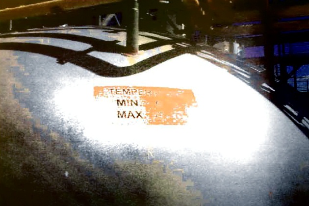
To further mitigate the issue of vapour generation, particularly on fully-refrigerated LPG carriers, the relief valves of some ships have dual settings to allow higher tank pressures during the loading operation. If relief valve settings are altered, the IGC Code requires that this is carried out under the supervision of the ship’s Master in accordance with approved procedures and as specified in the ship’s operation manual. The IGC Code requires that changes in the set pressures are recorded in the ship’s log and the current maximum allowable relief valve setting (MARVS) must be prominently displayed. Note that auxiliary settings are normally calibrated for specific valves. Relief valves will be reset to the seagoing position before the ship departs. When relief valve pressure settings are changed, the IGC Code requires that pressure alarms are readjusted accordingly.
Tank pressure management for pressurised LPG carriers
For pressurised LPG carriers the system will be similar and a vapour return may be fitted for safety relief purposes. However, a reliquefaction system is not fitted to such ships and loading is normally achieved by shore pumps creating sufficient pressure to allow cargo tank vapour to continuously condense into the bulk liquid. Alternatively, some liquid from the loading line may be directed to spray rails in the vapour dome to cause condensation in the tank, thereby reducing overall tank pressure.
Tank pressure management in LPG terminals
The reliquefaction capacity of a terminal with refrigerated cargo tanks is usually greater than that provided onboard ship. As a result, where an LPG vapour return line is used loading rates may be higher. While advantageous, such systems for LPG are relatively rare.
It may be difficult to account for the vapour returned to shore, especially if it is flared. This is particularly the case at the early stages of loading. Unless credit is given for the returned vapour, an overstatement of the Bill of Lading (B/L) quantity may result. Another potential problem experienced when using vapour returns in the LPG trade is that terminals may be concerned about the vapour quality to be returned to the shore. Residual nitrogen in the return acts as an incondensible during reliquefaction. There may also be concern about contamination with vapours from previous ship cargoes. However, the quality of the vapour can be easily confirmed by laboratory analysis.
Tank pressure management for LNG, ethylene and ethane
For LNG, ethylene and ethane cargoes, vapour return to the shore is normal during loading operations. Cargo is loaded via the liquid header and piped to the appropriate tanks. Vapour generated in the vapour space is returned to the shore using a high duty compressor.
When loading with a vapour return line in use, the loading rate is governed by:
- The flow rate acceptable to the ship and terminal;
- the pressure in the cargo tanks;
- the capacity of the compressor to return vapour ashore.
Applicable to all types
For all liquefied gas carrier types the management of cargo tank pressure is critical and, therefore, once loading is commenced at a slow rate it is normal practice to increase the loading rate in stages, ensuring the tank pressure is under control before increasing to the next stage. This is sometimes referred to as “ramping up“. The ramping up sequence and rates will usually be agreed at the pre-transfer meeting.
Reliquefaction plants and compressors will be prepared prior to the start of loading to ensure they are available as soon as the loading operation commences. If possible, at least one reliquefaction plant will be running before the loading operation commences.
Commencement of loading
Loading pressurised LPG carriers
Following drydock, fully-pressurised ships normally arrive at a loading terminal with their cargo tanks at atmospheric pressure. Initially, the ship requests vapour from the shore to purge any remaining nitrogen or contaminants from the tanks. This also allows the equalisation of ship and shore pressures. Thereafter, the method used is to start loading at a very slow rate.
In this case, as the liquid is allowed through the first valves, local flash cooling can occur and it is important to ensure that, at no time, tank or pipeline temperatures are allowed to fall below design limitations. This can be achieved by ensuring that the tank pressure is equal to or greater than the SVP, which is equivalent to the minimum steel temperature.
Loading pressurised LPG carriers from refrigerated storage
The cargo tanks on fully-pressurised ships are made from carbon steel that may only be suitable for a minimum temperature of between 0 °C and minus 10 °C (-10 °C). By contrast, LPG when stored in the fully-refrigerated condition can be stored at temperatures as low as minus 42 °C (-42 °C). Consequently, some refrigerated cargoes require considerable heating prior to loading on pressurised LPG ships. Given that such ships may not have cargo heaters fitted onboard, any required heating of the cargo will be carried out on shore.
On a pressurised ship, having loaded a cargo at dose to 0 °C, the cargo may warm up further during the voyage as a result of ambient conditions. The IGC Code only allows cargo to be loaded to such a level that the tank filling limit will never be more than 98 % at the highest temperature reached during the voyage (see point “Cargo tank loading limits” below). This means that, during the pre-transfer meeting, tank topping off levels will need to be established to allow sufficient room in the vapour space for liquid expansion on the loaded passage.
Where a terminal can expect to load fully-pressurised ships not fitted with their own heaters, in-line equipment fitted to terminal pipeline systems is needed. This usually comprises of:
- shore tank;
- shore cargo pump;
- shore booster pump;
- shore cargo heater;
- suitably sized marine loading arm (MLA).
Operation of the system takes the following form: Initially, until the back pressure starts to build up from the ship, loading is carried out by pumping only through the shore cargo heater. As the back pressure increases the shore booster pump is also brought into operation.
At the start of loading the pressure in a ship’s tank will usually need to be at least 3 bar if loading propane. This pressure will limit flashing off and sub-cooling as the first liquid enters the tank. At this time, in-tank cargo temperatures will be carefully watched. Sighting ice formation on the pipelines is an early indicator that temperatures onboard the ship are falling below operational levels for this ship type. In such cases, loading will usually be stopped until temperatures increase and the problem is resolved.
Loading semi-pressurised LPG ships from refrigerated storage
Refrigerated cargoes will be loaded directly on such ships without the requirement for heating. In addition, these ships can usually maintain fully-refrigerated temperatures on voyage so that a greater amount (ie mass) of cargo can be carried. The tank pressure will, however, always be maintained at slightly above atmospheric pressure. Temperatures of sub-cooled products under vacuum conditions can reach levels much lower than that which is acceptable for the tank material.
Loading refrigerated LPG carriers
Temperature limits for loading specific cargoes depend on individual vessel and tank design. Information specific to the vessel will normally be available in the cargo operating manual provided for the vessel. The minimum case typically found is that cargo tanks should be within 10 °C of the temperature of the cargo to be loaded. This would equate to around minus 32 °C (-32 °C) at the bottom of the tank for loading fully-refrigerated propane. Ideally, vessels will present tanks for loading that are as cold as possible, otherwise the result (ie cargo flashing) may put a strain on the capacity of the vessel’s compressors during loading.
Read also: Overview of the Carriage of Liquefied Gases by Sea
When liquefied gas is being loaded it is necessary to consider, for example, the location, pressure, temperature and volume of the shore tanks as well as the terminal’s pumping procedures. Fully-refrigerated ships usually load from fully-refrigerated storage, where tanks typically operate at a pressure of approximately 60 mbar. This pressure will allow the cargo at the bottom of a full shore tank to sustain a temperature of perhaps 1 °C warmer than its atmospheric boiling point.
When this cargo is pumped to the jetty the pumping energy required for transfer is dissipated in the liquid as heat, to which will be added the heat flow into the liquid through the pipeline insulation. The cargo may, therefore, arrive on the ship at an even warmer temperature. When loading without a vapour return line being used, the vapour that is displaced by the incoming liquid will be reliquefied on board. The power required for this, and to compensate for the pumping energy and the heat flux through the insulation, may leave little capacity for cooling the cargo during the early stages of loading.
A rise in ship’s tank pressure in the early stages of loading can also be controlled, to some extent, by loading limited quantities of liquid into the cargo tank via the top sprays (if fitted). This is intended to help to condense some of the cargo vapours.
Loading LNG carriers
After the ship’s lines have been cooled, loading is commenced at the minimum rate. The agreed ramping up procedures will be followed and the LNG carrier’s high duty compressor started as soon as the tank pressure begins to rise. In some cases it may be necessary to run a second high duty compressor (if fitted) during the early stages of loading. As the tank pressure can only be controlled by the use of the high duty compressor, the loading rote is determined by the rate at which vapour can be returned to shore. In some terminals it may also be permitted for the LNG carrier to burn gas as a fuel during the loading operation.
The use of automatic shutdown during topping off
When topping off tanks, it is not considered prudent for ship’s staff to rely on the use of the High-High level alarm system to close the tank valve. The High-High level alarm may activate the closing of the filling valve prior to the planned innage being reached, due to movement of the surface of the cargo as a result of sloshing or through agitation of the cargo due to boiling off at the surface.
It is also considered prudent, during topping off and all critical valve and machinery operations, to have an observer present to view and confirm the closing of the filling valve, rather than having to rely on the remote indication of the cargo control/automation system.
Operation of the reliquefaction plant during bulk loading of LPG
On LPG carriers with a reliquefaction plant, the efficiency of the earlier gassing-up operation will directly impact on the maximum loading rate and the time taken to achieve it. Significant quantities of incondensible gases may be present in tank atmospheres and, without vapour return to shore, these incondensibles will have to be vented via the ship’s purge gas condenser (where fitted) or, alternatively, manually from the top of the cargo condenser. Figure “Liquefied Petroleum Gas Reliquefaction PlantTypical purge gas condenser system” shows a purge gas condenser arrangement. Care is needed when venting incondensibles to minimise venting of cargo vapours to the atmosphere. As the incondensibles are vented, the condenser pressure will drop and the vent valve will be throttled and eventually closed.
It is prudent to keep a close watch on the ship’s cargo tank pressures, temperatures, liquid levels and interbarrier space pressures throughout the loading operation. Monitoring of liquid levels may present difficulties when the reliquefaction plant is in operation. This is because the liquid in the tank is boiling heavily at these times and, as a result, vapour bubbles within the liquid increase its volume, giving false readings when using float-type gauges.
Towards the end of loading, transfer rates will be reduced (sometimes referred to as “ramping down“), as previously agreed with shore personnel, to accurately “top-off” the tanks. On completion of loading the ship’s pipelines will be drained back to the cargo tanks. Remaining liquid residue can be cleared by blowing it ashore with vapour, using the ship’s compressor, which is common practice on LPG carriers. This is known as “hot-gassing“. Alternatively, this residue may be cleared by nitrogen injected into the MLA to blow the liquid into the ship’s tanks, which is normal practice on LNG carriers. This is not desirable on LPG carriers with reliquefaction plants as it introduces incondensible gases into the cargo system.
Once liquid has been cleared effectively, so that only vapour pressure remains, usually the pipelines will be depressurised then manifold valves dosed and the MLA disconnected from the manifold flange.
In many ports it is a requirement, before disconnection takes place, for the MLA and pipelines at the manifold to be purged free from flammable vapour. This is particularly true in the case of LNG carriers, where it is considered normal practice.
If cargo tank relief valves were set to higher “harbour settings” they will normally be reset to their “sea settings” before the gas carrier departs the berth (see article “Cargo equipment for gas carriers carrying LNG/LPGRelief valves for cargo tanks and pipelines“).
Operation of the reliquefaction plant during bulk loading of LNG
On conventional LNG carriers, the only option for cargo tank pressure control during loading is to send the vapour to the shore. For ships fitted with a reliquefaction plant, the overall plan for its use is usually agreed in advance with the charterer and terminal and discussed with the loading Master during the pre-transfer meeting.
Reliquefied LNG condensate is typically returned to the bottom of designated cargo tanks via dedicated pipelines. There may also be an interconnection between the dedicated condensate line and the LNG spray line, enabling the diversion of LNG condensate return to other cargo tanks as required. The spray line is normally used at the end of the loading operations to drain the liquid manifolds back to the ship’s cargo tanks, so it is important that the line up for the condensate return uses a separate line so that the two operations can continue independently.
The start-up of the reliquefaction plant should always be carried out following the recommendations of the equipment manufacturer and the procedures in the ship’s cargo operating manual. At the start of the reliquefaction process, the boil-off gas (BOG) compressor and the loading up of the plant are all controlled through pre-defined sequences. The cargo vapour is taken from the common vapour header and pressurised through the BOG compressor and, as it flows through the BOG condenser, the cold nitrogen from the nitrogen loop condenses the BOG vapour to liquid condensate. Depending on the flow rate, the condensate is returned back to the cargo tanks through either the LNG condensate pumps or by free flow (see also point “Operation of the reliquefaction plant on LNG carriers” below).
Cargo tank loading limits
Chapter 15 of the IGC Code recognises the large thermal coefficient of expansion of liquefied gas and gives requirements for maximum allowable loading limits for cargo tanks. This is to avoid tanks becoming liquid-full under conditions of surrounding fire.
As provided for in the IGC Code, the maximum volume to which any tank may be filled is governed by the following formula:
where:
- LL – loading limit expressed in %, which means the maximum liquid volume relative to the tank volume to which the tank may be loaded;
- FL – filling limit, which is 98 % unless certain exceptions apply;
- ρR – relative density of cargo at the reference temperature;
- ρL = relative density of the cargo at the loading temperature.
The default value of the filling limit (FL) of cargo tanks is 98 % at the reference temperature (R). An FL value greater than 98 % may be permitted provided that the conditions specified in the IGC Code are satisfied.
Where cargo vapour pressure/temperature control is provided, R is the temperature of the cargo on termination of loading, during transport or at unloading, whichever is greatest.
Refrigerated cargoes
For cargo tanks on fully-refrigerated ships, the IGC Code envisages PRVs set to open only marginally above the vapour pressure of the cargo at the maximum temperature it will reach over the whole cycle of loading, transportation and discharge. However, the loading limit must be such that, if a surrounding fire occurs, the tank will not become liquid-full before the PRV opens. Therefore, the amount of cargo shut-out required, over and above the normal operational considerations of cargo expansion, depends on the margin between the PRV setting and the maximum envisaged cargo vapour pressure on the voyage.
Where no cargo vapour pressure/temperature control is provided, the reference temperature is the temperature corresponding to the vapour pressure of the cargo at the set pressure of the PRVs. However, the IGC Code does allow additional cargo to be loaded in Type C tank ships under certain provisions. A brief description follows the examples below. This allowance can be granted to all Type C carriers, except those designated by Chapter 19 of the IGC Code as being 1G ships (ie specialised carriers transporting the most hazardous substances, such as chlorine).
Pressurised cargoes
For Type C tanks where there is no temperature control and the pressure of the cargo is dictated by the ambient temperature, the design pressure would then be not less than the gauge vapour pressure of the cargo at a temperature of 45 °C. For ammonia, the design vapour pressures would be not less than 17 bar, and for propane not less than 14,5 bar. Some pressurised ships with Type C tanks, therefore, have a pressure capability of up to about 18 to 19 bar, with PRVs designed for this pressure.
As an example, and using the IGC Code default FL value, the greatest volume the cargo will occupy within its tank will be 98 %. For the purposes of the loading limit calculation, the assumed temperature of the cargo in a Type C tank without temperature/pressure control would be the boiling point of the cargo at a pressure equal to MARVS. Cargo density corresponding to these conditions will almost certainly be much less than any density likely to be encountered during the actual loading, transit and unloading. It is this national cargo which occupies 98 % of the tank volume, and it is the weight of this cargo occupying 98 % of the tank volume that is the cargo tonnage that can be loaded. The actual loaded moss, therefore, takes up a volume, throughout the entire cargo transhipment, that is less than 98 % of tank volume. Simply put, this means cargo space is under-utilised and cargo “shut-out” occurs.
The IGC Code allows for operators of pressurised ships to take advantage of increased loading limits. In order to do so, ship operators will generally have to demonstrate to the Flag Administration that the cargo tank venting systems are adequate to deal with all aspects of two-phase flow, which may occur if the PRVs were to lift at the increased loading levels. If the tank vent system provisions of the IGC Code are met, then the relative density (ρR) value in the loading limit (LL) formula can then be defined as:
ρR – relative density of cargo at the highest temperature which the cargo may reach upon termination of loading, during transport or at unloading, under the ambient design temperature conditions.
The expression “ambient design temperature conditions” is linked to the IGC Code performance specification for temperature control of cargoes, which states that the upper ambient design temperatures are based on a sea temperature of 32 °C and an air temperature of 45 °C, although the Flag Administration may adjust these values to account for specialised trading patterns, etc.
Examples
Case 1
A fully-pressurised ship loading propane at 20 °C with relief valves set at 16 bar.
Reference temperature 49 °C (corresponding to SVP of 16 + 1 = 17 bar for propane)
- Density of liquid propane at 49 °C – 452 kg/m3;
- Loading temperature 20 °C;
- Density of liquid propane at 20 °C – 502 kg/m3
Therefore, the tank can be filled to 88,2 % of tank volume.
Case 2
A semi-refrigerated ship loading propane at minus 42 °C (-42 °C), with relief valves set at 5 bar and having no additional pressure relieving facility fitted.
Here, since no additional pressure relief is fitted in accordance with the IGC Code, the reference temperature is taken as the temperature corresponding to vapour pressure at the set pressure of the relief valves, ie a temperature corresponding to an SVP of 5 + 1 = 6 bar.
- Reference temperature – 8 °C;
- Density of liquid propane at 8 °C – 519 kg/m3;
- Loading temperature – minus 42 °C (-42 °C);
- Density of liquid propane at minus 42 °C (-42 °C) – 582 kg/m3;
Therefore, the tank can be filled to 87,4 % of tank volume.
Case 3
A fully-refrigerated ship loading propane at minus 42 °C (-42 °C) with relief valves set at 0,25 bar.
- Reference temperature – minus 37,5 °C (-37,5 °C);
- Density of liquid propane at minus 37,5 °C (-37,5 °C) – 577 kg/m3;
- Loading temperature – minus 42 °C (-42 °C);
- Density of liquid propane at minus 42 °C (-42 °C);
Therefore, the tank can be filled to 97,1 % of tank volume.
The advantages of these amendments are demonstrated in Case 1 of the worked examples. Should a ship be on a long voyage and likely to encounter seas at 32 °C and air temperatures of 45 °C for prolonged periods, the prediction of the highest cargo temperature then becomes, say, 38 °C. Under these circumstances, the loading limit becomes 92 % of tank volume. If however, it can be shown that the ship will operate in temperate waters and that the highest cargo temperature is 25 °C, then the loading limit becomes 96 %. If, in Case 1, the highest cargo temperature anticipated is 20 °C, the density ratio is 1,0 and the loading limit 98 %. For Cases 2 and 3 of the worked examples, the loading limit normally becomes 98 %.
For ship operators to take proper advantage of these rules they may wish to have performance details that show Flag Administrations how quickly a fully-pressurised ship’s cargo may warm up during the voyage. Additionally, a clear indication of the route that the ship will take, and the ambient conditions existing along that route, should further justify the selected highest temperature in the calculation.
More detailed information is contained in the SIGTTO publication: “Application of Amendments to Gas Carrier Codes Concerning Type C Tank Loading Limits” (Reference 2.61).