Dive into the intricate world of LNG carrier operations with our comprehensive guide to LNG vaporiser.
Explore their purpose, operating principles, setup, operational procedures, and alarm settings, ensuring optimal functionality and safety at every step of the journey.
LNG Vaporiser
Reference: SIGTTO “LNG Shipping Suggested Competency Standards”, Sections:
1 Have an awareness of its purpose and operating principles:
2 Know and understand its principles, operating parameters, the outlet requirements and limitations:
- temperature requirements.
3 Know and understand operational requirements and procedures:
- the relationship between steam supply and capacity of vaporiser;
- condensate level control;
- outlet temperature control mechanisms and methods used to control vaporiser outlet temperature;
- setting up;
- starting;
- manual and automatic operation;
- shutdown.
4 Know and understand their alarm settings and resulting actions.
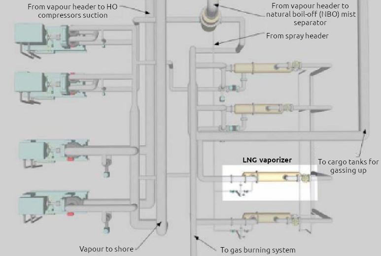
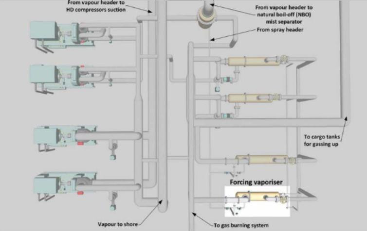
The LNG vaporiser is used for the fol lowing purposes:
- to assist in discharge of cargo at the design rate when the lack of a vapour return from the shore would cause a reduction in the cargo tank pressure;
- if the shore is unable to supply a vapour return, liquid LNG is fed to the vaporiser by using one stripping pump or by bleeding from the liquid header. The vapour produced leaves the vaporiser at approximately minus 140 °C (-140 °C) and is then supplied to the cargo tanks via the vapour header. Vapour pressure in the cargo tanks will normally be maintained at 90 mbar (minimum 25 mbar) during the whole discharge operation.
Moss type ships:
- if necessary, in the case of Moss ships, additional vapour can be generated by LNG being supplied by the stripping/spray pump to the tank spray rails;
- to purge cargo tanks with vapour after inerting with IG and prior to cooldown. LNG is supplied from the shore to the vaporiser via the stripping/spray line. The vapour produced is at a temperature of +20 °C, and is then passed to the cargo tanks. The design capacity of the vaporiser will determine the time that this cargo operation will take;
- the LNG vaporiser can also function as the emergency forcing vaporiser in the event of the forcing vaporiser failing.
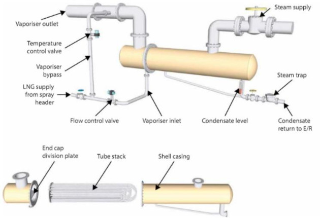
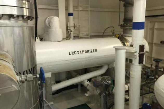
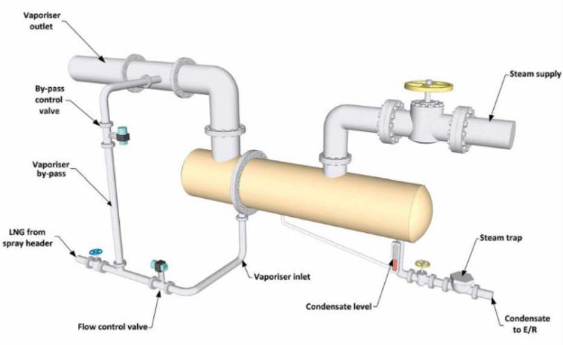
Each vaporiser is a shell and tube type heat exchanger, situated in the cargo compressor room. The heating surface consists of straight tubes arranged so that cargo vapour flows through the tubes and steam condenses outside them. The end covers are welded to the tube sheets but are flanged so that the tubes can be inspected or plugged on board the ship if required.
It should be noted that, if the vaporiser is to be used, it must be fully warmed through prior to the admission of LNG.
On completion of any operation the vaporiser outlet valve must be left open to the vapour header until all entrapped liquid has been boiled off and the vapour remaining is at ambient temperature.
Note that 1 m3 of LNG liquid will create approx 620 m3 of LNG vapour at atmospheric pressure. It is, therefore, possible to produce dangerously high pressures within the vaporiser if it is shut down with LNG entrapped.
| LNG vaporiser/typical details | |
|---|---|
| Type | shell and “U” tube design |
| Heating medium | saturated steam |
| Inlet temperature of steam | +169 °C |
| Maximum gas flow | 24 500 kg/h (unloading condition) |
| Inlet LNG temperature | minus 163 °C (-163 °C) |
| Outlet gas temperature | minus 140 °C (-140 °C) to 20 °C |
| Capacity | 8 000 MJ/h |
| Operated by | steam at 10 bars |
| No. on Board | 1 |
Cargo vaporisers generally use steam as their heating source. Alarms are provided for gas outlet temperature, high level and low temperature of the heating steam condensate returns.
LNG vaporisers should be started and stopped under local manual control and operate under suitable automatic control for each of the required modes of operation. Monitoring facilities should be in the cargo control room.
Suitable means should be provided to measure and maintain accurate outlet temperature, pressure and flow.
The LNG flow to the vaporiser must be automatically stopped in the event of either high condensate level or low condensate temperature.
LNG vaporiser outlet flow control
To control the outlet flow, a control system commonly called the integrated automation system (IAS) calculates the flow rate (by differential pressure across a standard orifice in the outlet piping), pressure and temperature. The IAS then manipulates the inlet pneumatic control valve in accordance with the calculated outlet flow rate (this operation can also be done manually).
If the vapour header pressure reaches 200 mbar, or a trip signal is detected during automatic control of the outlet flow rate, the flow controller is changed to manual mode and its output goes to 0 %. This prevents the inlet control valve from opening before the outlet flow rate can be recalculated.
LNG vaporiser outlet temperature control
To control the outlet temperature, the IAS controls the by-pass pneumatic control valve in relation to the measured outlet temperature.
If the vapour header pressure reaches 200 mbar, or a trip signal is detected during automatic control of the outlet temperature, the temperature controller is changed to manual mode and its output goes to 0 %. This prevents the by-pass control valve from opening until the vaporiser condition returns to normal status.
The steam condensate from the vaporiser is returned to the drains system via the cargo steam drains cooler and cargo condensate tank, the latter of which is fitted with a gas detector sampling point.
Typical operating procedures
Start-up and shutdown procedures must always be as per the manufacturer’s recommendations for the equipment.
Set the LNG pipelines as detailed for the operation about to be undertaken.
Setting up/starting instructions:
As an example, a basic LNG vaporiser is prepared for use as follows:
- open the shell side vent valve;
- crack open the shell side drain valve. Check that the condensate drain valves are open;
- ensure steam to deck is available and crack open the steam supply manual valve;
- when all air is expelled from the shell, shut the vent valve.
After approximately 30 minutes, when pressures and temperatures have stabilised on the vaporiser:
- slowly open fully the steam inlet manual valve;
- open the instrument air supply to the vaporiser controls;
- in the CCR, set the controls for the LNG vaporiser on the IAS mimic;
- slowly introduce liquid to the vaporiser, using manual control, to cool down the inlet. Check all flanges and joints for any signs of leakage;
- when vapour reaches a temperature of approximately minus 40 °C (-40 °C), switch the temperature and inlet controls for the liquid valve to remote and automatic.
| Alarms | |
|---|---|
| The following alarms and trip settings are typical | |
| Low condensate temperature alarm | +120 °C |
| A High condensate level alarm | |
| Low-low condensate temperature trip | +80 °C |
| A High-high condensate level trip | |
| A local manual trip | |
| Vapour header pressure high trip | 200 mbar |
| LNG vaporiser outlet temperature High alarm | +20 °C |
| LNG vaporiser outlet temperature Low alarm | minus 20 °C (-20 °C) |
Note that some vaporisers are fitted with interlocks so that the liquid LNG cannot be introduced until the steam valve is fully open.
Caution:
- Checks should be carried out around the LNG vaporiser and its flange connections during the operation;
- the vaporiser should be thoroughly warmed through with steam before the introduction of liquid. The by-pass valve in the heating steam supply pipe should be used as required for this purpose;
- the heating steam should be left cracked-on, using the supply steam by-pass facility to protect the vaporiser, until all LNG has been completely cleared from the unit.
Forcing Vaporisers
Reference: SIGTTO “LNG Shipping Suggested Competency Standards”, Sections:
1 Have an awareness of its purpose and operating principles.
2 Know and understand its principles, operating parameters, the outlet requirements and limitations:
- temperature requirements.
3 Know and understand operational requirements and procedures:
- the relationship between steam supply and capacity of vaporiser;
- condensate level control;
- outlet temperature control mechanisms and methods used to control vaporiser outlet temperature;
- setting up;
- starting;
- changing from manual to automatic operation (use of automatic controllers);
- shutdown.
4 Know and understand alarm settings and resulting actions.
The forcing vaporiser is used for vaporising LNG liquid to provide fuel gas to supplement the natural boil-off. This is normally required during high speed ballast passage (when consumption is higher than natural boil-off) and may also be required on a gas-only mode loaded passage (according to charterer’s instructions). Both the LNG and forcing vaporisers are usually situated in the cargo compressor room.
The LNG is supplied either by a stripping/spray pump or a fuel gas pump.
Flow is controlled by an automatic inlet feed valve that receives its signal from the consumer gas management system.
| Forcing vaporiser/typical detail | |
|---|---|
| Capacity | 4 500 MJ/h |
| Method of operation | steam at 10 bar |
| No. on board | 1 |
| Heating medium | saturated steam |
| Inlet temperature of steam | +169 °C |
| Inlet LNG temperature | minus 163 °C (-163 °C) |
| Outlet gas temperature | minus 40 °C (-40 °C) |
The forcing vaporiser should achieve an outlet temperature similar to that of the vapour header and be started and stopped under local manual control. It should have automatic capacity control from 0 % to 100 % of the consumer load and be integrated with the main propulsion plant control system. Appropriate monitoring facilities should be provided in the IAS to ensure accurate outlet temperature, pressure and flow measurement.
The LNG inlet flow to the unit must be automatically stopped in the case of high condensate level or low condensate temperature. Alarms are provided on the outlet gas temperature and high level and low temperature of the condensate water.
A forcing vaporiser is equipped with a temperature control system to obtain a constant and stable discharge temperature for the various ranges of operation.
The temperature of the gas produced is adjusted by spraying a certain amount of by-passed liquid into the outlet side of the vaporiser through a temperature control valve and liquid injection nozzles.
Read also: Properties of liquified gases
Both forcing vaporisers are fitted with spiral wires to promote turbulence, ensuring efficient heat transfer and production of superheated LNG vapour at the exit of the tube nests.
Outlet flow control
The flow rate is calculated by measuring differential pressure across a standard orifice arrangement. The IAS adjusts the inlet pneumatic control valve in accordance with the calculated outlet flow rate.
The flow rate is calculated by a flow meter that measures flow by differential pressure.This also provides temperature and pressure readings.
Condensate level control
The steam condensate from the vaporiser is returned to the drain system via the cargo steam drain cooler and cargo escape tank. The escape tank, which should be outside of the engine room, is fitted with a gas detector sampling point.
A re-evaporator is also used to ensure that accumulation of non-vaporised liquid at the vaporiser discharge is avoided and that the output is at a stable temperature.
This is made possible by:
- two knitted mesh filters are inserted in the gas flow path to fractionate the droplets and create the necessary turbulence to break down the small droplets injected into a fine fog of liquid gas and to moisten the mesh wires acting as a vaporising surface;
- two conical baffles installed in the tube to allow the eventually accumulated liquid to be directed into the gas stream on the pipe bottom.
Setting up and starting
Basic procedure for setting up and starting
Start-up and shutdown procedures must always be as per the manufacturer’s recommendations for the equipment.
A typical setting up process is as follows:
- ensure that the deck steam and instrument air supplies are available to the forcing vaporiser;
- open the shell side vent valve;
- crack open the shell side drain valve. Check that the condensate drain valves are open;
- crack open the steam manual supply valve (making sure that the steam to deck is available);
- when all air is expelled from the shell, shut the vent valve.
Starting
After approximately 30 minutes, when pressures and temperatures have stabilised on the vaporiser:
- slowly open fully the steam inlet manual valve;
- open the instrument air supply to the vaporiser controls;
- in the CCR, set the controls for the forcing vaporiser on the IAS mimic;
- fill up the vaporiser with liquid using manual control. Check all flanges and joints for any signs of leakage;
- when vapour is produced, switch the control for the liquid valve to remote and automatic operation.
Caution
- thorough checks around the forcing vaporiser and the associated flange connections must be conducted during operation;
- to protect the vaporiser, it should be thoroughly pre-heated with steam before the introduction of liquid;
- to protect the vaporiser,heating steam should be left cracked-on, using the supply steam by-pass facility, until all LNG has been completely cleared from the unit.
Shutdown
Shutting down:
- switch control to manual;
- stop the fuel gas pump;
- shut the liquid valve;
- shut the steam supply valve when no LNG remains;
- open the steam side vent and then open the drain when all of the steam has been vented;
- shut the vapour outlet valve when the heater has cooled down to ambient temperature;
- secure the rest of the system as required.
Alarms and resulting actions
The following are typical alarms and trips on a forcing vaporiser:
| Low condensate temperature alarm | +120 °C |
| Low-low condensate temperature trip setpoint | +80 °C |
| High condensate level alarm contact switch | |
| High-high condensate level trip | |
| Local hand manual trip | |
| Vapour header pressure high trip | 200 mbar |
| Forcing vaporiser steam pressure low | 5 bar |
| Forcing vaporiser steam inlet temperature high | +220 °C |
| LNG forcing vaporiser outlet temperature | High alarm: minus 30 °C (-30 °C) |
| Low alarm: minus 60 °C (-60 °C) | |