Learn how to effectively install and optimize Loran-C systems with our detailed guide. From selecting the right antenna and receiver locations to ensuring proper power and ground connections, we cover every step.
Explore strategies for minimizing interference and conducting thorough performance evaluations to achieve reliable navigation.
Introduction
The final article of this Loran-C category covers the important topics of receiver installation and related matters. Proper installation of a loran receiver and associated equipment is essential in order to realize the maximum utility from the system. As the following discussion shows, installation is far more than simply wiring up the receiver, turning it on, and getting the vessel underway. An otherwise excellent receiver, if improperly installed, may not perform as well as an inexpensive receiver calibrated and installed with care.
The chief consequence of installation errors is that the SNR of the received signal will be lower than it would have been with proper installation. In areas where the signal is very strong and in good weather conditions, it is possible that (aside from lower-than-expected SNRs) the improperly installed receiver will perform quite well. However, in areas where the SNR is normally lower, the added losses as a result of poor installation may cause the receiver to take longer to initialize, or to “crash” more often. Additionally, cycle slip errors may occur with greater frequency, and the effective range of the system at which usable loran signals can be acquired will be substantially reduced.
As with other articles, the material presented here is designed to supplement, but not replace, the instructions contained in the receiver owner’s manual. Users should carefully read the specific installation instructions contained in the owner’s manual.
Overall Sequence of Installation Steps
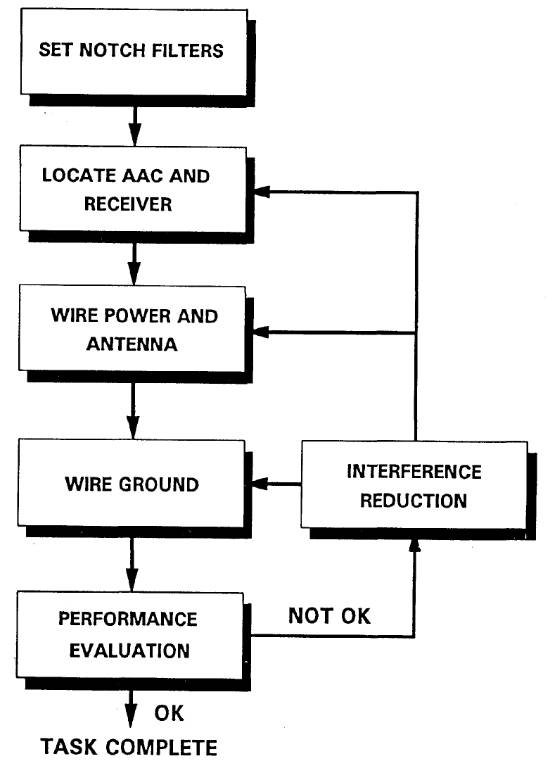
The overall job of installation andcalibration involves several steps shown schematically in Figure 1. These include:
- Setting the receiver’s notch filters (if adjustable);
- Locating, fastening, and wiring the receiver’s antenna and antenna coupler;
- Finding a suitable location for and mounting the receiver;
- Connecting the antennalead and supplyingpower to the receiver;
- Grounding the receiver;
- Performance evaluation;
- Interference reduction (if necessary);
With the exception of items 1 and 8, these steps are addressed in this article.
Setting adjustable notch filters is a specialized task and beyond the scope of this handbook. Ideally, these notch filters should be “optimized” for the intended cruising area considering the known sources of interference. Likewise, connecting the Loran-C receiver interface to other shipboard electronics is straightforward, but depends upon many application-specific factors (e. g., the particular communication protocol required) and is not discussed here.
The material given here is designed to supplement the owner’s manual for those users who elect to install the receiver and associated equipment. Although installation is not especially difficult, it needs to be done properly. Therefore, the user may wish to consider having this installation done by an electronics technician. The cost of professional installation is usually not great, and the user can generally be assured that the job will be done correctly. For those on a tight budget, do-it-yourself installation not only saves money but also permits the user to learn more about the receiver. Aviation users should check applicable Federal Aviation Administration (FAA) regulations to determine the personnel qualifications necessary to install loran receivers and antennas.
The material presentedin this article applies chiefly to marine users. Other users may find elements of this discussion of interest.
Antenna/Antenna Coupler (AAC) Location
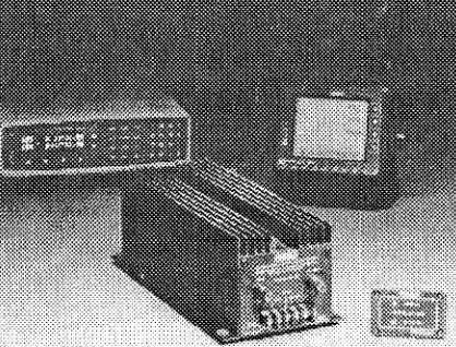
As received from the factory, the Loran-C typically includes the receiver itself, an antenna, an antenna coupler, a coaxial cable for the connection from the coupler to the receiver, a power cord, and miscellaneous installation hardware (e. g., yoke mount, nuts, bolts, screws). Use only the antenna supplied with the receiver or an alternate recommended by the manufacturer.
Antenna/antenna coupler (AAC) location is a prime determinant of the performance of the loran receiver, and careful thought must be given to this choice. Guidelines for location of the AAC unit on vessels are as follows Location of aviation receivers and antennas is not discussed in this article.x:
- The AAC should be located several feet away from the loran receiver, or other potential sources of on-board noise (see below).
- The AAC should be mounted vertically, or as near to vertical as possible. In some installations (see below) it may prove advantageous to tilt the antenna slightly.
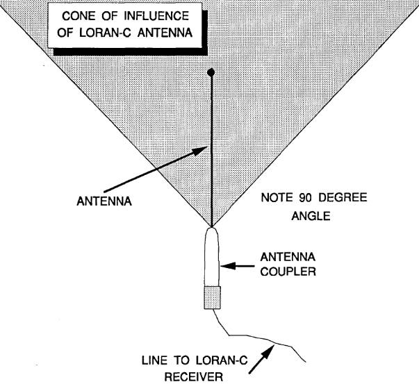
- Unlike a VHF-FM radiotelephone, Loran-C reception is not limited by line-of-sight constraints, so the loran antenna height, per se, is not that important. However, masts, other metal structures (e. g., tuna towers, cargo booms, outriggers, “flopper stoppers“), shrouds, stays, and other antennas (radar, RDF, VHF-DF, VHF-FM, etc.) can interfere with loran reception and degrade the SNR. The easiest way to visualize the potential for this interference is to imagine a “cone of interference” (COI) as shown schematically in Figure 2. This COI originates at the base of the loran antenna and emanates outward and upward at a 45 degree angle to the antenna. Ideally, the loran antenna should be mounted at a location such that no “foreign object” penetrates this COI. This may not always be possible, particularly in the case where the vessel has (4) an “antenna farm.” However, the loran antenna should be located as far from the other antennas as possible; preferably at least 1 to 2 meters (3-6 ft) from other antennas. The antenna can sometimes be tilted slightly to ensure that the COI is free of metal objects.
- Mounting the loran antenna on the mainmast of a sailboat or atop the flying bridge of a cabin cruiser will usually satisfy the COI constraint. However, there are often competing requirements for this location. Radar and VHF-FM, for example, are limited by line-of-sight constraints and, for this reason, require the highest possible location to ensure maximum range. On a sailboat with two masts, a practical alternative is to locate the VHF-FM antenna atop the mainmast arid the loran antenna atop the mizzen mast. On sailboats with only one mast the loran antenna is often mounted on a stern rail (always above the stern rail). On powerboats the loran antenna should be separated as much as possible from other antennas.
- Coaxial cable is used to connect the antenna coupler to the receiver. Where possible, the length of this cable should beminimized. However, it can belengthened (special connectors are available from marine electronics dealers). Likewise fiberglass extension “masts” can be used to increase the height of the loran antenna. Ensure that these extensions are well braced.
- The coaxial cable should be routed so as to avoid contact with wires supplying power to the receiver or other equipment. As well the coaxial cable should be loosely clamped, and not in any area where standing water can be found, nor where it could be exposed to high temperatures.
One useful idea is to mount the antenna temporarily, pending completion of performance checks on the receiver (see below). The best spot may then be determined by a “trial-and-error” process of evaluating several alternative antenna locations.
Receiver Location and Mounting
After (provisionally) mounting the antenna and antenna coupler, the next step is to select a location for and mount the Loran-C receiver. Generally speaking, the most important consideration in placing the receiver is to locate it at either the navigation station or the helm. If the steering and course correction features of the receiver are to be used, it is preferable to locate the receiver where it can be easily seen from the helm. There are several other factors that should be considered in selecting a location for the receiver.
These include:
- The display of the receiver should not be located where it would be exposed to direct sunlight. Strong light makes it more difficult to read the display and, moreover, may actually damage the display.
- The receiver should be located at least 1 meter (3 ft) away from the vessel’s magnetic compass to minimize possible deviation errors. Additionally, the receiver should not be mounted close to radar, radios, echo sounders, and other electronic equipment capable of causing on-board interference (see below).
- The receiver should be located in a vibration-free environment that will not get excessively (e. g., over 50° centigrade) hot. (It should be in a well-ventilated area.) Users who elect flush mounting should ensure that there is adequate ventilation behind the bulkhead. Small fans can be used to increase ventilation, but these may need to be filtered (see below) to suppress electrical noise. The receiver should not be placed where it will get wet (salt spray, rain, condensation, wash water). Although some receivers are more water resistant than others, salt spray does not improve the performance of any receiver.
Most receivers can be mounted in several ways, for example, flush-mounted through a bulkhead or yoke mounted from below or above. It is sometimesconvenient to mount the receiver on an overhead near the windshield at the helm, but remember that windshield wiper motors cause electrical noise that can interfere with the receiver.
Power
Most Loran-C receivers are designed to operate on 12-volt direct current (DC) power. Some receiver can be powered from a 24-volt system. It is recommended that the vessel’s electrical system be wired so that the battery supplying power to the loran is different from the starter battery. The benefit of this arrangement is that the loran is less likely to crash if the vessel’s engine(s) need to be restarted. Devices are commercially available that supply backup power or supplemental voltage to a loran during engine start. These units (which also contain noise filters as well as a supplemental battery) function as a buffer between the vessel’s fluctuating input voltage and the loran receiver. These backup power units and voltage “conditioners” are cheap insurance against inopportune receiver crashes.
As noted in Loran-C Receiver Features and Their Use“Understanding Loran Receivers: Features and Functionality”, loran receivers do not draw a great deal of current, so the power cables do not need to be large. many manufacturers recommend that the loran receiver be wired directly to the battery, by-passing any power “bus” or terminal strip supplying power to other devices to lower the likelihood of interference. At a minimum, ensure that the loran is not wired through the ignition system. Check to see if the receiver is internally fused, otherwise it is necessary to provide an external fuse of appropriate current rating. Check that the polarity of the power line is correct, otherwise the receiver may be damaged. Route the power line to the loran so that it is as far as possible from other electrical cables.
It is recommended that the loran be powered by a battery separate from that used for starting the engine, and/or that a backup power voltage conditioner unit be used.
Ground
With the exception of portable units, all loran receivers need an external ground. If the vessel has a steel hull, the loran receiver can be grounded directly to the hull. For wood or fiberglass vessels, the receiver can be grounded to the engine block or the negative side of the vessel’s battery (if this is grounded to the engine block). The best ground connection is to a ground plate or ground shoe that is attached to the hull. These plates are manufactured by several companies for exactly this purpose. Ground connections can be made with copper wire, but braided copper strap provides improved grounding.
Proper grounding is important to ensure high SNRs.
Preliminary Performance Evaluation
The next step in the installation procedure is to turn on the loran receiver, and measure the SNRs of the master and secondary stations. This should be done first with all other electronics (or other possible interference sources) turned off. SNRs will fluctuate, and several values can be averaged for best estimates. These “baseline” SNRs should be compared with values suggested by the manufacturer. If the vessel’s dock is located near to cliffs, bridges, or other “difficult” reception areas, it may be necessary to move to a better location to obtain valid performance data.
Next, each piece of gear should be turned on one-by-one and the engine started. The resulting SNRs should be checked to determine if there is any appreciable reduction in SNR. The one-at-a-time approach enables interference sources to be identified. If SNRs remain high and within the manufacturer’s recommended limits (e. g., no more than a 20 % drop in SNR), the installation is complete, and provisional connections can be finished. If not, on-board sources of interference will have to be controlled.
Sources of Interference
Table 1 provides a list of common sources of on-board electrical interference that can affect loran reception. The list is organized into four major classes:
- engine and drive, including engine ignition systems, the voltage regulator, engine alternator (frequently a major noise source), and the propeller shaft (when turning);
- auxiliary and related, including DC motors on water and bilge pumps, wind-shield wiper motors, power generators, and DC motors and blowers;
- marine electronics of various types, shown in Table 1, and;
- items grouped under the rubric of “amenities,” including microwave ovens, refrigerators, TV sets (another bad offender), and fluorescent lighting.
In broad terms, electrical noise may reach the loran receiver by one or both of two pathways, radiation or conduction. Radiated noiseis picked up by the loran antenna, while conducted noise enters the receiver through the power cable and/or ground.
| Table 1. An illustrative list of on-board sources of electrical interference | |
|---|---|
| Category | Item |
| Engine and Drive | Gasoline Engine Ignition Systems Voltage Regulator Engine Alternator Propeller Shafts (when turning) |
| Auxiliary & Related | DC Motors on Water and Bilge Pumps Windshield Wiper Motors Power Generator DC Motors on Blowers |
| Marine Electronics | Inverters on Marine Radars Other Loran Units Single-Side Band Radios When Transmitting Fish Finders Echo Sounders Autopilots Tachometers Wind Speed Indicators Water Speed Indicators |
| Amenities | Microwave Ovens Refrigerators TV Sets Fluorescent Lighting |
| NOTE: All of these sources are capable of interfering with loran reception. Depending upon many factors (e.g., distance from receiver and antenna) these may not produce interference in each installation. Generally, these noise sources will not produce interference unless in actual operation. | |
Some sourcesof on-board interference affect the loran principally through conduction, others through radiation, and some through both pathways. For example, the alternator(used tocharge the vessel’s batteries) is often a major source of radio frequency (RF) noise. Alternator diodes switch on and off with each cycle of output voltage at a rate depending upon the engine revolutions per minute (RPM). This switching causes “spikes” of energy at radio frequencies and produces the RF noise.
The RF noise travels throughout the vessel along the power wiring (conductive noise) and also radiates into space (radiation noise). The Loran-C receiver picks up the RF noise, along with the loran signal – resulting in a lower SNR. As engine RPMs are increased, the rate at which these spikes are generated likewise increases. As more current is drawn by the electrical equipment in use, larger pikes result. RF noise from an alternator is generally at a maximum when the engine is started, particularly if the batteries are in a low state of charge. Although the alternator can create substantial interference problems, these can often be eliminated by the installation of a noise filter (see below) installed on the alternator.
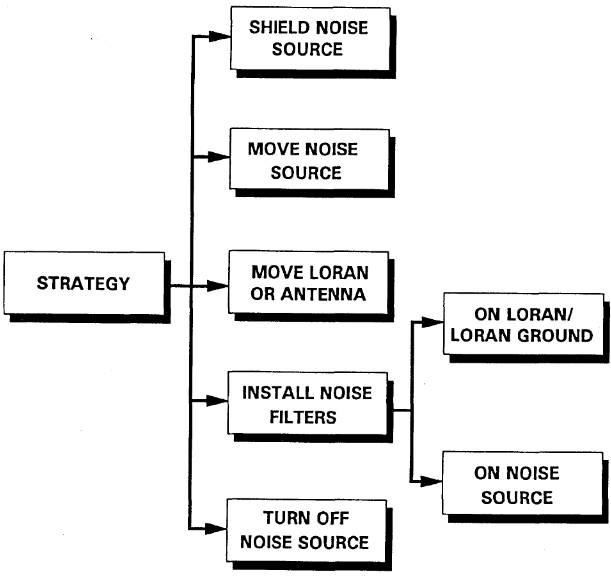
Strategies for Noise Reduction
If the performance checks indicate that noise reduction is required, there are several strategies that can be employed to mitigate or eliminate this shipboard noise. Notch filters are designed to eliminate external noise sources, and normally should not be used to control on-board noise sources. These are shown schematically in Figure 3. In brief, these include:
- Shield the noise source. In some cases it may be possible and desirable to shield the noise source. Shielding can be done with aluminum foil, “noise tape,” and/or copper screen available from marine supply houses. Outboard motors, principally those with high-voltage capacitor discharge ignition, can sometimes be a troublesome noise source. Some manufacturers sell noise reduction kits for these engines. But, failing this, household aluminum foil (Dahl, 1986, Miller and Malone, 1988), cemented to the inside of the fiberglass engine cover and grounded, can serve as an effective shield. Plastic-cased ignition coils sometimes radiate excessively and should be replaced or shielded.
- Increase the distance between the noise source and the loran receiver andlor AAC and the offending noise source. This is why provisional mounting is recommended. In some cases, moving the antenna or the loran receiver only a few feet will substantially reduce, the noise.
- Turn off the noise source. For many items in the “amenity” group, such as television sets or microwave units, a simple policy of refraining from use of the amenity while the loran is in use will be the easiest solution to an on-board noise problem.
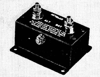
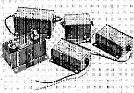
- Finally, electronic filters (resister capacitor circuits) can be used. These filters (illustrated in several of the photographs of this article) can be installed on the noise source directly and/or on the loran receiver and/or ground. Manufacturers produce an integrated family of these filters, each designed for a specific purpose. Noise filters can often be used to great effect on the vessel’s alternator. For best results, follow the manufacturer’s recommendations. Installation directions are also provided by the manufacturer of the filters.
Generally, changing the placement of the receiver and/or converter will solve a noise problem. Failing this, filters are a good choice. For the special case of noise caused by the rotation of the propeller shaft(s), it is often sufficient (Miller and Maloney, 1988) to attach a grounded bronze “finger” or brush that wipes and maintains electrical contact with the shaft(s).
If all of the above ideas fail, either an electronics technician or the manufacturer should be consulted.
The noise-reduction steps given here will not only improve loran reception, but also will reduce noise levels in other on-board electronic equipment.
Final Performance Checks
After completing the installation and noise reduction steps, another series of performance checks should be made to verify the satisfactory operation of the loran receiver.
Finally, those who elect to install a loran receiver should remember the remark of the Compte De Buffon (1707-1788) that “Genius is only a greater aptitude for patience.”

- Abramowitz, M., et al. “Approximate Method for RapidLoran Computation,” Navigation; Journal of the Institute of Navigation, Vol. 4, No. 1, March 1954, pp. 24-27.
- Alexander, G. “The Premier Racing Tool,” Ocean Navigator, Issue No. 20, Jul/Aug 1988, pp. 37, er seq.
- Anonymous. “Loran: Installation Pitfalls, and How Friendly Should Your Loran Be?” Practical Sailor, Vol. 11, No. 24, December 15, 1985, pp. 1, et seq.
- Anonymous. Manual on Radio Aids to Navigation, International Associationof Lighthouse Authorities, Nouvelle Adresse, 13 Rue Yvon-Villarceau 75 116, Paris, 1979.
- Appleyard, S. F. Marine Electronic Navigation. Routledge and Kegan Paul Ltd., Boston, MA, 02108, 1980.
- Ashwell, G. E., B. G. Pressey, and C. S. Fowler. The Measurement of the Phase Velocity of Ground Wave Propagation at low Frequencies Over a Land Path. Proceedings of the Institute of Electrical Engineering (London) 100 Part III, 1953.
- Bedford Institute of Oceanography. Loran-C Receiver Performance Tests, Bedford Institute of Oceanography, P. O. Box 1006, Dartmouth, NovaScotia, Canada, B2Y 4A2.
- Blizard, M. M. et al. Harbor Monitor System Final Report, CG-D-17-87, ADA 183 477, Dec. 1986, Available through the National Technical Information Service, Springfield, VA, 22161.
- Blizard, M. M., Lt. and CWO 3 D. C. Slagle. Differential Loran-C System Final litter, Draft, United States Coast Guard, January 1987.
- Blizard, M. M. and D. C. Slagle, “Loran-C West Coast Stability Study,” Proceedings of the Fourteenth Wild Goose Technical Symposium, Wild Goose Association, Bedford, MA, 1985.
- Brogdon, B., “Loran Expansion,” Ocean Navigator, Issue No. 42, SeptfOct 1991, pp. 87, et seq.
- Brogdon, W. “Loran Hook, a Little Known, Foible Explained,” Boating, August 1991, p.42.
- Brogdon, W. “Electronic Errors,” Ocean Navigator, Issue No. 40, June 1991,pp. 70, etseq.
- Brogdon, W. “Pathfinders,” American Hunter, Vol. 19, No. 7, July 1991.
- Burt, W. A., et al. Mathematical Considerations Pertaining to the Accuracy of Position, Location, and Navigation Systems, Part I, Stanford Research Institute, 1966. Available from National Technical Information Service, AD-629609, US Department of Commerce, 5825 Port Royal Road, Springfield, VA 2215 1.
- Canadian Coast Guard, Aids and Waterways Branch. A Primer on Loran-C, Ottowa, Ontario, Canada, 1981.
- Connes, K. The Loran, GPS & NAVICOMM Guide, Butterfield Press, 1990.
- Culver, C. “A New High Performance Loran Receiver,” Proceedings of the Sixteenth Annual Technical Symposium, The Wild Goose Association, 20-27 October 1987, pp. 282, et seq.
- Dahl, B. “Adopting Loran-C to Everyday Navigation,” Cruising World,May 1983,pp. 40-45.