Explore the world of Loran-C navigation systems in this detailed guide. Learn about the generations of Loran-C receivers, their key features, and how they function to provide accurate position information.
- Introduction
- Read Your Owner’s Manual
- Generations of Loran-C Receivers
- Features
- Basic Function: Reception and Display of Position Information
- Displays
- Keypad
- Remote Readout
- Coordinate Conversion
- Notch Filters
- Integration with Other Systems
- Data Bases
- Magnetic Variation
- Power Requirements
- Automatic Alarms and/or Status Indicators
- Recording SNR Data in the Navigation Log
- Navigation Features
- Waypoints
- Cross Track Error
- Other Alarms
- Arrival Alarm
- Boundary (Border) Alarm
- Passing Alarm
- Anchor Watch
- Course and Speed Information
- Velocity Made Good (VMG)
- Velocity Towards Destination (VTD)
- Time Information
- Routes
- Voyage Planning
- Interface With Electronic Charts
- Aviation Lorans
- Pitfalls
Discover the integration of Loran-C with other systems, the importance of waypoints, alarms, and voyage planning, and understand the potential pitfalls of using Loran-C in modern navigation.
Introduction
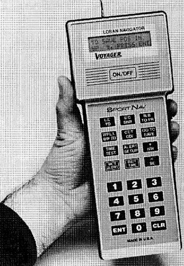
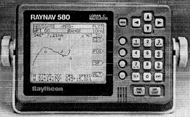
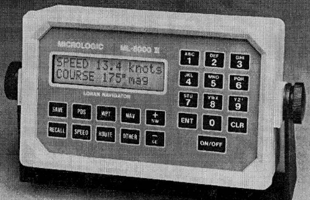
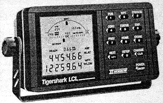
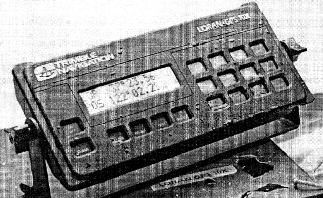
Earlier articles have addressed the theory of the Loran-C system. This article narrows the focus to the shipboard component of the system – Loran-C receivers. Specifically,this article provides an overview of the key features and characteristics of Loran-C receivers relevant to the navigator. Readers wishing to learn about the operating instructions for a specific make and model of loran receiver are advised to consult the appropriate owner’s manual for details. As of this writing, there are at least 25 brand names of marine Loran-C units, (and several manufacturers of aircraft lorans Some of these are undoubtedly made by the same manufacturers, with only minor changes in the size or shape of housing or other “cosmetic” differences to distinguish “private label”.x) and most manufacturers produce several models – so the user has a wide array of choices. Available Loran-C receivers differ substantially in design, type of displays, and operating instructions, making it impractical to cover this informationin requisite depth in the article of reasonable length. Moreover, any such discussion would rapidly become obsolete because new models are continually being introduced.
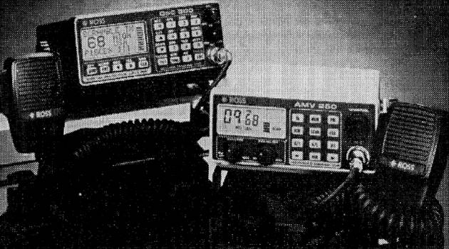
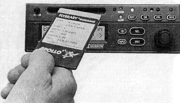
This article serves as a supplement to the owner’s manual, providing perspective, rationale, and theory to explain the features of modern Loran-C receivers. Prospective purchasers of a loran receiver may also find this article useful to identify the potentially desirable features of loran sets. Readers should be aware, however, that neither the Coast Guard nor any other agency of the US government has the responsibility of performance evaluation or publication of comparative performance statistics of recreational vessel loran receivers although marine lorans used on certain types of vessels and aircraft lorans must meet technical performance criteria. (There are private sector publications that do present technical data and frank evaluations of Loran-C receivers.) It is also worth reminding the reader that receiver photographs included in this handbook are for illustrative purposes only and should not be construed as endorsements of any particular make or model.
As with this handbook generally, the focus of this article is on marine users. Where appropriate, supplemental material relevant to other users is included.
Read Your Owner’s Manual
Although all Loran-C receivers operate on the same general principles, there are important differences among these receivers in features, methods of operation, and even in the definitions of terms used in the operating instructions. For example, one manufacturer uses the term “velocity along route” (VAR) to describe the component of the aircraft’s or ship’s speed over the ground in the direction of the course (more below), while other manufacturers use terms such as “velocity made good” (VMG) or “speed of advance” (SOA) to describe the same term. As a second example, one manufacturer calculates the “time-to-go” (ITG) to the next waypoint as the distance to the waypoint (distance-to-go, DTG) divided by the speed over the ground, another as the DTG divided by the component of the ground speed in the direction of the waypoint.
The control buttons of different receivers have different names (or alphanumeric designators), and operating procedures likewise differ.
The only way to master a particular make and model of Loran-C receiver is to read the accompanying manual, and call the manufacturer (or dealer) if you have any questions Commercial videotapes are available to supplement the owner’s manual for many makes and models.x. The old saw: “when all else fails, read the directions,” is simply not good advice when it comes to today’s sophisticated marine electronics or avionics. There is no substitute for careful study of the owner’s manual.
Owner’s manuals differ significantly in the amount of detail presented, and in their clarity and accuracy. The prospective purchaser is well advised to read this document and include the quality of the manual among the attributes to be considered in the purchase decision.
The old saw: “when all else fails, read the directions,” is simply not good advice when it comes to today’s sophisticated marine electronics. There is no substitute for careful study of the owner’s manual.
Generations of Loran-C Receivers
Although the earliest Loran-C receivers were a substantial improvement over Loran-A receivers, these early (so-called first generation) Loran-C receivers were extremely primitive by today’s standards. The first Loran-C models were difficult to operate (similar to the Loran-A sets), and provided only TD information. Later (so-called second generation) models offered little more than a display of measured TDs from two secondaries in a Triad. Users would need to specify the GRI and secondaries to be tracked, and take the measured TDs, convert these to latitude and longitude if desired, and otherwise do the time-honored navigator’s “days work” of plotting, determining course to steer, estimated time enroute (ETE), estimated time of arrival (ETA), and the many other tasks common to the practice of navigation.
The advent of microchips and miniaturization of computers over the years since the Loran-C system has been in place has created a “revolution” in the design and features of the modern receiver. Loran-C receivers now select chains and secondaries, automatically convert TDs to latitude/longitude, warn of any lack of system integrity, do many of the typical calculations made by navigators, and “talk” to other onboard electronic systems, such as radar, electronic charts, autopilots, and other marine electronics. If the early receivers could be called “radios” in some sense, the later receivers should really be termed “navigation computers.” Additionally, the price of full-feature lorans has decreased substantially over the years, as manufacturers amortized research and development expenditures, captured economies of scale, and responded to competitive pressures. Receivers have, therefore, become much more affordable for owners of recreational vessels and aircraft.
Considering the sophistication of most modern receivers, these are remarkably “user friendly” easy to operate. Nonetheless, it requires time and some diligence to master the use of a given receiver – not unlike that required to use a computer. Although some lorans are much easier to operate than others, all require a modicum of user sophistication.
Features
This section describes the relevant features of various Loran-C receivers now available commercially. Not all receivers include all of the features discussed below, but all of these features can be found among commercial loran sets. Some manufacturers use company-unique or trade names-different from those in this hand-book – to describe these features.
Receivers differ widely in the number and type of features offered. The features discussed here provide a useful sample for the prospective purchaser.
Basic Function: Reception and Display of Position Information
In broad terms, the functions of the Loran-C receiver are to acquire and lock on the appropriate transmissions and, at a minimum, to display the TDs associated with the selected master-secondary station pairs. Additionally, all receivers now being marketed have the capability to convert from TDs to latitude and longitude, termed a coordinate conversion capability. All modern receivers also have a “navigation mode” that enables the user to monitor the progress of a flight or voyage, and make necessary corrections to stay on course.
Receiver circuit designs are generally proprietary and, in any event, beyond the scope of this handbook. Nonetheless, receivers do employ different hardware and software It is convenient to distinguish between the receiver’s “front end,” or ability to acquire and lock-on to signals, and the “software” or computer programs that are used to process and interpret these signals. Sensitivity, dynamic range, and minimum SNRs necessary for acquisition and lock are largely (but not entirely) determined by the front end. Navigation features, latitude/longitude conversions, and ease of use are more a function of the software.x, and differ substantially in their ability to acquire and process signals. These differences can be important to the mariner – particularly a mariner who frequents “fringe areas” near the limits of the coverage area or areas where interference is high. With some older receivers, it is necessary to select the chain and the station pairs as part of the setup process. Newer receivers incorporate automatic transmitter selection (ATS) or automatic initialization, as it is sometimes called. If the receiver has this capability, all the user need do to initialize the set is to enter the user’s latitude/longitude, and the set automatically selects the “best“ “Best” is placed in quotation marks for the reasons discussed in “Loran-C Position Determination and Accuracy”.x GRI and station pairs. This feature is convenient, but (as noted in Loran-C Position Determination and Accuracy“LORAN-C System: Accuracy and Position Determination”) it is sometimes necessary to override this automatic selection.
Once the GRI and the secondaries are selected, the receiver goes through a sequence of steps to search for, acquire, settle, and “lock-on” to the transmissions from the desired secondaries. Table 1 identifies the “generic” steps in signal acquisition and lock. The time for receivers to complete these steps varies with the receiver and the SNR of the master and the secondaries. Typically, this time varies from less than a minute for very strong signals to 15 minutes or more for signals with low SNRs. Most receivers display an alphanumeric code to identify the stage of the setup procedure. As noted in earlier chapters, the requisite SNR for reception differs with the receiver. The SNR required for acquisition is generally greater than that for tracking. This is why it sometimes occurs in an out-and-back trip that the loran receiver can continue to track a previously acquired signal in circumstances where the same receiver could not acquire the signal.
| Table 1. Generic stages for signal reception | |
|---|---|
| Stage (Search Status) | Description |
| Search and Acquisition | Looking for signals of selected GRI, i. e. establishing the approximate location in time of the master and each of the selected secondaries with sufficient accuracy to permit subsequent settling and tracking. |
| Settling | Detecting the front edge of Loran-C pulse. Selecting the correct cycle (3rd) to be tracked. |
| Tracking (Lock) | Tracking 3rd cycle, i. e., maintaining the synchronization of the receiver with the selected signals. Lock on is the state of the receiver in which acquisition and settle have been completed and the receiver is tracking the selected signals. |
Some receivers can acquire and track only a master and two secondaries, while others can acquire and track all usable secondaries in a chain. Although two loran LOPS are sufficient to determine a fix, reception of additional secondaries is desirable. As noted, the availability of an additional secondary can be used to resolve ambiguous positions when operating near areas of baseline extension. Moreover, statistical techniques can be used (Kalman filtering) to derive more precise position information if three or more LOPs can be measured. The receiver’s computer automatically determines the position which minimizes the weighted mean square error of all the LOPs. At least one receiver manufacturer has designed a Loran-C unit ‘with the capability to use signals from two chains simultaneously – a so-called dual-chain receiver. Statistically optimal positions can be derived from LOPs from many stationpairs from the two chains. An advantage claimed for the dual chain receiver is that it can provide accurate positions at greater distances than single-chain counterparts.
It is important to note, however, that simply because a Loran-C receiver tracks all secondaries does not mean that it is capable of using information from more than two master secondary pairs in the manner noted above. Prospective purchasers are cau tioned toread the user’s manual carefully on this point.
Users should consult their owner’s manuals to determine exactly which chains can be received by the set – some are capable of tracking all extant GRIs (including the USSR system), while others are more limited. The introduction of new chains (e. g. the recent SOCUS and NOCUS chains) may require software revisions for adequate reception on older models.
Notes:
- Different receiver manufacturers use slightly different terminology for these stages.
- Some receivers display numeric codes to identify the various stages.
- The time required to complete each stage depends upon the SNR of the signal at the receiver.
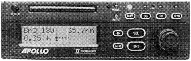
Displays
Nearly all modern marine loran receivers use a liquid crystal display (LCD), which is energy efficient and easy to read in daylight as well as darkness Some earlier marine lorans used light emitting diodes (LED) which draw more power and are more difficult to read in strong light conditions. Aircraft lorans use LED displays more frequently.x. Dimmer switches are handy to control nighttime cockpit or nav-station light levels. These displays indicate position information (TDs or latitude/longitude) as well as many other ancillary quantities (stations in use, signal characteristics, navigational information, etc.). The size of the display screen varies among models. Some models feature “paged displays” in which different information is displayed on different “pages” of the display. By pressing a mode or other key, the user can page through the available information. Some lorans can interface with voice synthesizers, so that the user does not have to look at a display to acquire necessary information – a mechanical voice continually broadcasts data from the receiver. Some users find lorans equipped with voice synthesizers to be very convenient; to others this feature is an irritating distraction.
Prospective receiver purchasers are well advised to pay particular attention to the type of display screen of the set. This may seem an odd point to emphasize, but it is absolutely true that the most sophisticated Loran-C receiver in the world is of little use, unless the navigator can quickly read and interpret the available information. As with many other features of the loran receiver, the design of the display reflects numerous compromises and tradeoffs.
Read also: Loran-C Position Determination and Accuracy
A large screen, for example, is more costly, consumes more power, and may be incompatible with the overall size of the receiver. The available information from a Loran-C receiver (see below) includes status indicators and warning information, identification of the GRI and secondaries in use, SNRs of the master and secondaries chosen, alarm settings, position information (in latitude/longitude or TDs), and navigational information (e. g., waypoint descriptors, bearing and distance to waypoint, ETE/ETA information,crosstrack errors, speeds, and courses, to cite just a few elements).
In total, a modem Loran-C receiver may have the capability of displaying hundreds of pieces of potentially relevant data. Practical constraints limit the overall size of display screens, and size of lettering/numbering, so that it would be impossible (let alone confusing) to present all this information on one display. Segmenting the display into “pages,” each with defined and logically grouped contents is a viable design alternative. However, paged displays do not solve all problems. For example, a user cannot simultaneously examine the contents of more than one page – so that not all information is rapidly accessible.
Large clear numerals or letters (without distracting and hard-to-read letters made from numerals) are easiest to read. It is also helpful if the screen can display several items at once (perhaps in different sizes) so that the user does not continually have to switch pages to find related information. Some information is more easily and rapidly understood in analog (e. g., pointers, arrows, etc.) rather than digital form. Arrows, symbols, or mini-charts, if well designed and logically grouped, can also enhance the interpretabilityof adisplay. So-called “menu” screens (i. e., those with self-prompting inputs) can ease the task of entering data.
Display screens differ in the “viewing angle,” through which the numbers can be clearly read. Some displays are quite difficult to read when not standing directly in front of the set.
Receiver displays are a very important feature. Ideally, the display should be large and easy-to-read, keeping key information readily in view.
Finally, the display should be evaluated in terms of where the loran receiver will be mounted in the vessel. Mounting directly in front of the helm station (e. g., on a power vessel) may not require a display as large as if the set were mounted at some distance from the navigator’s eye, as might be required on a sailboat. Aircraft lorans are generally rack mounted on the instrument panel.
Keypad
The keypads used on loran receivers differ. Some use “membrane” or flat keypads, others use raised keys. In general, raised keys (as on a computer keyboard) have a better feel, and are easier to use. Membrane keypads are easier to make waterproof or water-resistant, however.
Some receivers emit a “beep” when a key is depressed and the information is entered. This feature compensates, to some degree, for the lack of tactile sensation when using a membrane keyboard.
The size of the keys likewise differs among receivers. Closely spaced keys invite entry errors, particularly when on the bridge of a pitching or rolling vessel, or in the cockpit of an aircraft encountering turbulence.
Nearly all receivers have a numeric keypad (in addition to function keys). On some models, however, it is necessary to push “+” or “–” buttons to increase or decrease an entry – an inconvenience when entering waypoint coordinates.
Some marine lorans have “calculator style” numeric keyboards – i. e., with the keys 7-8-9 on the top row. Other marine lorans have “telephone style” numeric keyboards – i. e., with the keys 1-2-3 on the top row. There is no “best choice” for the keyboard type,but a matter of individual preference.
Remote Readout
Some receivers offer the option of a remote readout or display to be used instead of, or in addition to, the principal readout. Receivers with this feature can be used to provide navigational information in two locations, such as at the bridge and at a separate navigator’s station. Of course, the same effect can be achieved by using two lorans – one at each station – but the remote readout ensures that both stations display the same navigational information, and at a cost somewhat less than that for a second loran.
Coordinate Conversion
All modern marine Loran-C receivers have the capability of displaying position information as TDs or as latitude/longitude. Aircraft lorans use latitude/longitude exclusively. TDs are what is measured by the receiver in all cases, and these are converted to latitude/longitude by mathematical algorithms using ASF information (e. g., the tables shown in The Loran-C System: A More Detailed View“Understanding Loran Transmitters and Hyperbolic Systems”) stored in computer memory A few loran receivers being marketed as of this writing do not have internal ASF tables or the capability of manually entering these factors.x. Some manufacturers have gone to great lengths to ensure that ASFs are as accurate as possible.
Although the ASFs stored in the internal memory of the Loran-C receiver are highly accurate for many makes and models, this is not true uniformly. Studies conducted at the Coast Guard Research and Development Center in Groton, CT (see Frazier, 1988), indicated that the internal ASF tables in some models were very inaccurate for some locations. Indeed, for some makes and models, the internal ASF corrections resulted in greater latitude/longitude errors than if no corrections were applied at all. As of this writing, there is no industry standard for coordinate conversion RTCM is presently working on such a standard. Interested readers should contact RTCM for details and current information.x, and each manufacturer uses a slightly different variant. It is possible, therefore, for two Loran-C receivers located next to each other to register exactly the same TDs, but slightly different positions in latitude and longitude terms.
Because of this lack of standardization, and because ASFs are only approximate in any event, use of TDs is preferred for most accurate navigation – although accuracy differencesmay not be large for “top-of-the-line” Loran-C receivers.
As noted above, aircraft loran receivers provide latitude/longitude information only. The width of a typical airway [“highway” in the sky] is 4 nautical miles either side of a centerline, so precise position information is less important in the enroute mode. When making instrument approaches to airports, standard ASFs appropriate to each airport are entered into the loran from the published instrument approach procedure.
When prestored ASFs are being applied, there is generally some indication on the display (e. g., the code sequence “ASF“) to indicate that this is the case. Most lorans also enable the user to input a predefined ASF, latitude/longitude offset, or bias as an alternative to the stored values.
Experienced navigators needing optimal Loran-C accuracy are well advised to use TDs rather than latitude and longitude. Published waypoints are often given in TDs as measured.
Notch Filters
Loran-C signal reception can be impaired by interference from other signals, broadcast on slightly different frequencies (e. g., radio broadcast stations, military radio transmitters, and other navigation equipment). Below you can see pictures, which provides a list of known sources of interference in the United States, Canada, and Mexico. The severity of the effects of interfering signals is a function of many factors, but interfering signzls can reduce the SNR of the loran signal and degrade the accuracy of the position determined.
Sources of Interference
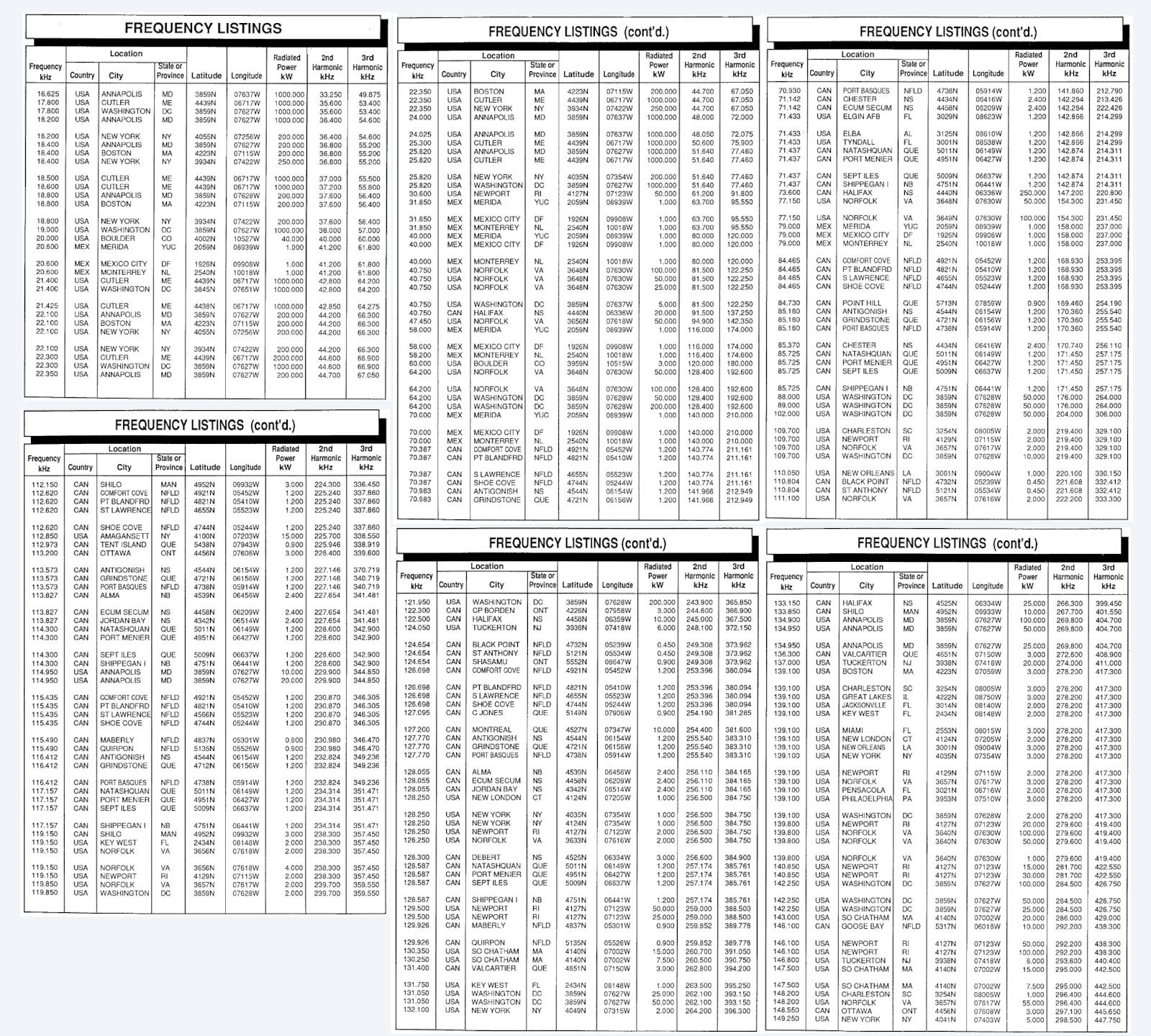
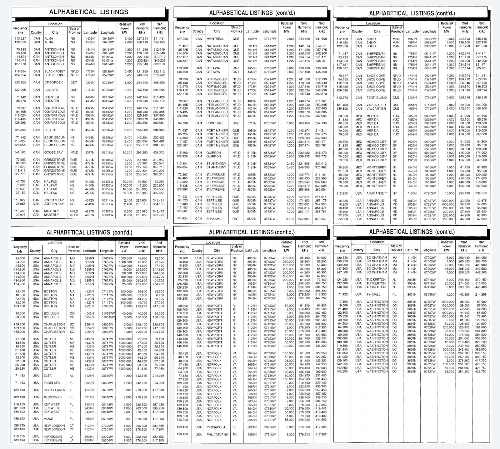
To avoid the degradation in SNR associated with these interfering sources, loran sets are equipped with so-called notch filters that can be used to attenuate or “notch out” the interfering signal. Some receivers contain built-in spectrum analyzers to display levels of interfering signals, a useful feature when setting adjustable notch filters. Some receivers are equipped with preset notch filters, others with adjustable notch filters, and yet others with so-called “Pac-man” or “seek and destroy” filters. These latter filters automatically search for interfering signals near the loran band and dynamically notch out this interference. Refer to the owner’s manual for instructions on how to use the notch filters for a particular make and model of receiver.
It should be noted that the purpose of notch filters is to control the effects of interfering signals, not any noise or interference associated with shipboard equipment. Control of internal noise sources is addressed in more detail in Installation and Related Matters of Loran-C“Complete Guide to Loran-C Installation and Related Matters”.
Integration with Other Systems
Loran-C receivers can be integrated with other shipboard systems in two ways. Some Loran-C receivers are actually “built into” another piece of electronic gear, e. g., a depth sounder, fish finder, or plotter. Some receivers are integrated with GPS, offering additional flexibility and redundancy. As well, most receivers have output jacks with a standardized output (three common protocols are the National-Marine Electronics Association, NMEA 0180, 0182, and 0183 formats) that enables interconnection with:
- plotters,
- video charts,
- autopilots,
- radars.
Some models can also be interconnected with a gyrocompass or fluxgate compass and speed log – enabling the electronic determination of the set and drift of the current. This interface capability can be a considerable help to the navigator. Prospective purchasers should ensure that the correct output formats are available to tie into ancillary equipment.
Data Bases
Some Loran-C receivers, typically those intended for use on aircraft, but also some marine models, incorporate a self-contained “data base.” On an aircraft loran, for example, this data base would contain the locations of the thousands of airports throughout the country. The user can call up attributes of the airport (e. g., the longest hard surfaced runway) with only a few keystrokes, and navigate to this airport. In the event of an in-flight emergency, the loran receiver can display the distance and bearing of the nearest airfield having the requisite runway characteristics. Likewise, marine loran receivers with data bases contain the locations of buoys and other features of navigational interest. One marine loran comes with a data base of approximately 8 000 lights and 6 000 buoys, along the coast of the continental United States, Great Lakes, Hawaii, and Alaska.
| Table 2. Current draw for several types of marine electronic equipment: Turning off the Loran-C is unlikely to feature in any load-shedding strategy | ||
|---|---|---|
| Equipment Type | Typical Current Draw (Amperes) | Remarks |
| RDF/ADF | 0,5-3,0 | Older units likely to be less efficient. ADFs (aircraft type) are at the upper-end of this range. |
| Loran-C | 0,07-1,75 | More complex Loran-C, including integrated loran/GPS navigation systems draw more current. |
| VHF-Radio | 1,0-5,5 | Varies depending upon whether transmitting or operating in receive only. |
| Video Charts | 0,8-2,5 | Based upon sample of 10 makes and models. |
| Video Plotter | 1,1-8,3 | Based upon sample of 11 makes and models. |
| Weather Fax | 2,0-3,3 | Depends upon whether receiving or only in standby mode. |
| Radar | 3,0-18,0 | Based upon sample of 62 makes and models. Power required a function of maximum range of the radar. |
| Depth Sounder | 0,3-5,0 | Depends upon whether indicator only or video or paper chart type. |
| Autopilot | 8 | NA |
| Navigation Lights | 3 | Based upon three 12-watt lights, this number could be larger. |
| Tape Deck | 1,25 | Based upon sample of 8 makes and models. |
| Bilge Pump | 1-15 | Unlikely to run continuously. |
| Cabin Lights | 1-4 | Varies with number and wattage. |
| Single-Side Band Radio | 1 Receive 12 Xmit | Not needed with VHF range of shore. |
| NOTE: The above table is furnished for illustrative purposes only. Consult the owner’s manual for each piece of equipment for details. | ||
A data base can be very convenient, but it is also necessary to have some means to update the data base as the locations of the entries or other information changes. With aircraft lorans, a cartridge is shipped periodically to update the original factory supplied data.
Magnetic Variation
Most Loran-C receivers are equipped with a chip that provides magnetic variation data throughout the areas of the world covered by the loran chains that can be used by the receiver. On some models, this data base includes average annual changesin variation. Once the user enters the date and year, the receiver can compute the variation at any relevant location.
In practice, therefore, the user can do all navigation with reference to either true or magnetic north. Deviation is not accounted for on any production loran as of this writing. When directions are referenced to magnetic north, the loran receiver displays a “flag,” such as “MAG” or other abbreviation to indicate that directions are referenced to magnetic, rather than true, north.
Power Requirements
Nearly all Loran-C receivers used by recreational vessels or aircraft operate on DC power. In most cases, these receivers are designed to use on board power. Consult the specifications for each receiver for the acceptable voltage range (e. g., 10-15 volts or 7-40 volts). However, some receivers are portable, and use self-contained batteries (e. g., 6 AA cells). Power batteries should not be confused with those lithium batteries required to maintain the receiver’s waypoint memory These memory batteries need to be replaced periodically to ensure that memory contents are not lost. A battery lifetime of from 3 to 7 years is typical for lithium batteries used for this application.x.
If the voltage drops outside of the acceptable range (because the batteries are run down, or as a result of starting the engine), the loran receiver may “crash,” and have to begin the entire acquisition-to-lock cycle anew. This could cause a problem if, for example, the engine(s) were shut down to increase the likelihood of hearing a sound signal from a critical buoy in circumstances of restricted visibility. If, on restarting the engine(s), the loran were to crash, the navigator would lose critical navigational data at an inopportunetime. Where possible, it is desirable to use a different battery to power marine electronics from that used to start the engine(s).
Power requirements for Loran-C receivers are typically quite modest. As Table 1 shows, Loran-C receivers do not draw much current (e. g., 0,15 to 1,75 amperes among a sample of 20 receivers), at least in comparison to many other types of marine electronics found on board a recreational vessel. Thus, to operate a Loran-C receiver for a 24-hour period would require from 3,6 to 42 ampere-hours.
Power requirements for Loran-C receivers are typically quite modest compared to other marine electronics. This enables Loran-C receivers to be operated almost continuously on sailboats, power vessels or aircraft experiencing alternator failure.
Power requirements for marine electronics are relevant not only for selecting the storage batteries and sizing the generator (alternator), but also for designing a “load shedding” strategy in the event of alternator failure. A heavy-duty marine battery of 100 ampere-hour rating, for example, could supply current to service the ship’s electronics load at the rate of 100 amperes for one hour, 50 amperes for two hours, 25 amperes for three hours, etc., without being recharged. In the event of alternator failure, all nonessential electrical equipment would be shut off to conserve the battery. Mariners are left to decide exactly what is “nonessential,” depending upon the circumstances of the voyage. As Table 2 indicates, the current drain for most lorans is sufficiently small that the loran receiver would probably not have to be shut down in the event of alternator failure. Even this small draw could be reduced by the simple expedient of shutting off the display lights and using a small flashlight for illumination if necessary.
Automatic Alarms and/or Status Indicators
Most Loran-C receivers have the capability to display a variety of automatic alarms and/or status and warning indicators. Table 3 provides a sample of these alarms and status and warning indicators for marine lorans. These alarms and the names and display codes vary fromreeeiver to receiver, so the owner’s manual should be consulted for details. For example, one receiver model combines all of these alarms into one warning flag, “wait,” to indicate that positions displayed by the loran may be unreliable.
| Table 3. Automatic alarms, status, and warning indicators Above list is illustrative, not all receivers are able to display each warning or status message.x | |
|---|---|
| Name Narnes given in this list are illustrative. Actual designations vary from receiver to receiver.x | Brief Description |
| Accuracy | Alphanumeric display to warn that accuracy of displayed position may be poor. |
| Ambiguity | Alarm to note that ambiguous position information is being received – probably as result of operating in area of baseline extension. |
| No Solution | Receiver unable to compute latitude/longitude from available information – may be provided in lieu of “ambiguity” alarm. |
| SNR | Warns that SNR of master or secondaries is poor. |
| Cycle Select | Warns that receiver may not be tracking correct cycle in Loran-C pulse. |
| Blink | Warns whenever blink code is received. Latitude/longitude or TDs will blink on and off as well on some receivers. |
| Battery | Feature on portable loran sets to warn that batteries used as power supply are low and need to be replaced. May also present remaining battery life in hours. |
| Power Failure | Warns that battery voltage (shipboard) batteries has dropped below usable voltage (e. g., 10 volts) and that restart procedures must be used. |
| Memory Battery | Warning on some lorans that internal battery is weak or has failed and memory contents may be lost. |
| ASF | Indicates that ASFs permanently stored in memory or manually entered are in use for latitude/longitude conversion. |
| MAG | Indicates that course and bearing displays are reference to magnetic, rather than true north. Variation may be input manually or stored on memory chip. |
| Manual Offset | Indicates that user-supplied offsets (ASFs) are being applied for latitude/longitude conversions. |
| ECD | Warns that envelope-to-cycle difference is out of specification and that the receiver may be tracking the wrong signal. Display may be integrated with cycle alarm. |
On this model “wait” is displayed if there is a low SNR, cycle error, blink code, etc. Other models are capable of displaying much more detailed information. In general, it is desirable to have more detailed information, because the user can often intervene (e. g., by switching secondaries) to remediate the problem.
With one exception, the definitions of the alarms and status indicators in Table 3 are clear and do not need elaboration. It is appropriate, however, to say a few words more about SNR indications on Loran-C receivers. SNRs are very important to the user. “Low” SNRs warn the user of possible acquisition or tracking difficulties, the need to switch secondaries, and/or that on-board electrical interference problems exist. “High” SNRs are generally desirable – but “abnormally high” SNR values in what would otherwise be fringe areas could warn of skywave contamination (see The Loran-C System: A More Detailed View“Understanding Loran Transmitters and Hyperbolic Systems”). For these and other reasons, SNR values are important to the mariner.
Some Loran-C receivers display SNR information only in qualitative terms, e. g., by letter codes (e. g., “A” = excellent, “B” = very good, etc.) or word descriptors such as “very low” or “very high.” Other sets display a two or three digit numerical code – e. g., ranging from 00 to 99, where 00 is worst and 99 is best. Pay particular attention to the text in the owner’s manual to interpret the SNR values provided by a particular make and model.
A measure of the signal-to-noise ratio favored by electrical engineers is the SNR in decibels, abbreviated dB. The SNR in dB is numerically equal to 20 log (SNR). Thus, for example, an SNR of 0,5 would be equal to -6,02 dB. Equivalently, the SNR corresponding to a particular dB reading is SNR = 100,05 dB. Table 4 shows the relationship between the SNR (as a fraction) and the equivalent in decibels.
| Table 4. Relation between SNR and decibel SNR measurement | |
|---|---|
| SNR | Decibels (dB) |
| 5,00 | 13,98 |
| 4,00 | 12,04 |
| 3,00 | 9,54 |
| 2,00 | 6,02 |
| 1,00 | 0,00 |
| 0,90 | -0,92 |
| 0,80 | -1,94 |
| 0,70 | -3,10 |
| 0,60 | -4,44 |
| 0,50 | -6,02 |
| 0,40 | -7,96 |
| 0,33 | -9,54 |
| 0,30 | -10,46 |
| 0,25 | -12,04 |
| 0,20 | -13,98 |
| 0,15 | -16,48 |
| 0,10 | -20,00 |
| 0,05 | -26,02 |
As can be seen from inspection of this table, the SNR in dB will change by approximately six units whenever the actual SNR is either doubled or halved. Some Loran-C receivers have the capability of displaying SNR values in dB. This display is preferable because, alone among the various methods of indicating SNR, the actual SNR value can be calculated from the dB figure In principle, SNR values could also be calculated from a two-digit or three-digit code. However, a survey of 20 owner’s manuals for different sets has failed to find one example where this correspondence has been provided.x.
SNR displays are useful for setting notch filters, determining the sources and significance of shipboard electrical interference, detecting skywave contamination, and selecting secondaries for use. Quantitative displays showing the actual SNR (as a ratio or in decibels) are best.
Recording SNR Data in the Navigation Log
Navigators should make it a practice to record the SNR for various stations as a memo item in the navigation log for each trip. Over time, a data base can be assembled that will provide the navigator with a series of “norms” for comparison. It is only by this method that the navigator has the information to determine that something is amiss.
Perhaps there are storms between the LORSTAs and the vessel, perhaps a newly installed piece of shipboard equipment needs noise suppression,or the receiver’s ground has been impaired, etc. These phenomena or problems can only be detected by a systematic comparison of SNR values with historical norms which depend upon the make and model of receiver, installation technique, and vessel location.
Navigation Features
The above features of loran receivers would be, in themselves, more than satisfactory for navigational purposes. However, all modern lorans also incorporate a wide variety of navigational functions that, taken together, transform loran from simply an instrument to determine position (such as a hand bearing compass or a sextant) into a complete navigational system. Navigational information and functions of modern Loran-C receivers are next discussed.
The Loran-C receiver “knows” the user’s position (in TD and/or latitude/longitude terms) at any instant in time. As well, the receiver has a very precise “clock.” Knowledge of position and time information enable the calculation of the user’s speed, course, and other relevant information for navigation.
Waypoints
As noted in earlier articles, all Loran-C receivers in current production have the capability of entering and storing “waypoints.” These waypoints are simply sets of coordinates which describe a location of navigational interest. Waypoints could include a dockside location where the vessel is berthed, fixed and floating aids to navigation, channel centerlines, turnpoints, productive fishing areas, wrecks, shoals, etc.
Aviators would typically define different types of waypoints from those given above. Possible waypoints relevant to aviation uses of loran could include airports, locations of the initial approach fix, locations of radionavigation aids, airway intersections, locations of published holding fixes, turnpoints, and other relevant information. Note that aviation lorans equipped with a data base may have many of these locations preprogrammed in the loran. A subscription service is available to update these locations.
Waypoints can generally be entered into (and stored by) the loran either by visiting the area and pressing the appropriate control button on the set, or can be entered as coordinates (typically as TDs, latitude, longitude, or as distance and either true or magnetic bearing from another waypoint). The number of waypoints that can be stored in the receiver’s memory varies by make and model, but most receivers can store 100 or more waypoints. Waypoints are stored as a waypoint number and set of coordinates. Some receivers permit an alphanumeric waypoint designator (e. g., “home,” “buoy 01,” etc.) to be used.
In use, waypoints are either places to be visited (e. g.,checkpoints along a route) or places to be avoided (e. g., shoals, rocks, or other obstructions to navigation). Often a navigator will lay out a sequence of waypoints, linked into an overall “route” for the voyage. The Loran-C receiver keeps track of the user’s progress from waypoint to waypoint. At all times, the user can determine the “distance-to-go” (DTG) and “bearing” (BRG) to the next waypoint in sequence, an angular course direction to the next waypoint, and the “time-to-go” (TTG) to reach the next waypoint. These functions are discussed in more detail below.
Cross Track Error
The cross track error, often abbreviated XTE on loran displays, is the perpendicular distance from the user’s present position to the intended track between waypoints. Nearly all modem Loran-C receivers can display the XTE – optionally in nautical or statute miles. Crosstrack error is illustrated in Figure 1, which shows the aircraft’s intended track (the solid line) between two waypoints and the actual track, denoted by the dashed line.
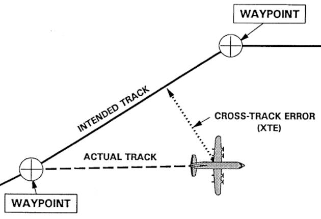
In this illustration, the aircraft has drifted to the right (south) of course. The “bearing” (BRG sometimes called course-to-steer [CTS]) would be the angle from the aircraft’s present position, and the DTG, the distance (great circle) from the user’s present position to the next waypoint in sequence.
Knowledge of the XTE enables the user to alter the vessel’s or aircraft’s course to compensate for the observed drift, effects of maneuvering to avoid traffic, and/or inattention at the helm. Additionally, many receivers display a course deviation indicator (CDI), often by an arrow, that indicates the appropriate angular correction to return to course. It is important to remember that the mere fact that the loran indicates the XTE does not imply that there is safe water or airspace between the vessel and the waypoint. It is the navigator’s responsibility to check the appropriate charts to determine if a course alteration can be made safely. If an autopilot is coupled to the loran receiver, the autopilot will maintain a correct course to the next waypoint.
To simplify navigation, many receivers enable an adjustable XTE alarm to be set, so as to warn the user when a pre-defined XTE tolerance is exceeded. Figure 2 shows this graphically.
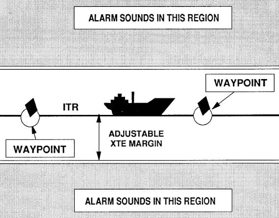
As in the first illustration, the vessel is assumed to bein transit between two waypoints. The XTE alarm is an audible alarm that can be set to warn the mariner of any excursions outside of a “lane” of adjustable width between the waypoints. In Figure 2, for example, the XTE alarm would sound whenever the vessel strays into the shaded area.
An XTE alarm would typically be set for voyage legs where navigational hazards (e. g., shoals, rocks, heavily traveled shipping lanes, fish trap areas) lie to one side or the other of the intended track. The XTE alarm should be set so as to enable the vessel to return to course in ample time to avoid the navigational hazard.
Therefore, the navigator should allow an adequate margin of safety to ensure safe passage. This safety margin should reflect, among other things, an allowance for the accuracy of the loran system, the “reaction time” of adistracted helmsman, and the speed and reaction capability of the vessel. Although vessel are generally thought of as being comparatively slow, these can still cover a surprising distance in a short span of time. A sport fisherman on plane at 30 knots, for example, will cover more than 1 500 ft in 30 seconds.
Incidentally, it is noted above that the distance to go (DTG) to the next waypoint is the great circle distance between the vessel (or aircraft’s) present position and the waypoint. In circumstances where the vessel’s intended course differs from this great circle, e.g., because the vessel is following a meandering river, this DTG could be a significant understatement of the actual distance remaining. In turn, other navigationally relevant information based upon this quantity, such as the time to go, would also be in error. To minimize this error, the navigator should (within the memory limitations of the receiver) enter as many waypoints as necessary to represent the vessel’s meandering course to destination. Failing this, the navigator should recognize that the distance to go may understate the actual miles over the route to be followed.
Other Alarms
The XTE (sometimes called off-course) alarm is only one of several adjustable alarms that can be set by the user to assist in navigation. Table 5 provides a list of several other alarms commonly incorporated into Loran-C receivers. These are next discussed. Although these are described as “audible alarms” in the manufacturer’s literature, the soundof the alarm may not carry very far – particularly in a noisy environment – and some manufacturers provide for an external connection to a loud alarm An external connection to a loud alarm could be particularly useful if an anchor alarm is being set. While at anchor crew might not be near the helm, and might even be sleeping.x.
| Table 5. Adjustable alarms or typical Loran-C sets | |
|---|---|
| Name | Description |
| Arrival | Alarm to indicate that vessel has penetrated to within an adjustable radius of the next waypoint. |
| Passing | Alarm to indicate that vessel has passed a waypoint and is enroute to the next waypoint in a route sequence. Sometimes termed “arrival off course alarm” or “perpendicular crossing alarm“. |
| Off Course (Cross Track Error) | Alarm to indicate that vessel has cross track error larger than preset amount. |
| Boundary (Border) | Alarm to indicate that vessel has penetrated a defined exclusion zone parallel to the track between two waypoints. |
| Anchor Watch | Alarm to indicate that vessel has departed from within a predefined swing circle about waypoint. |
Although alarms can be used to great advantage, these should be used judiciously. Many types of modern marine electronics are fitted with alarms – those described below for the loran, depth alarms on the sonar, intrusion alarms on radar sets, etc. The sound of numerous alarms going off simultaneously may actually complicate decision making in a hazardous situation. So, while it is nice to have the capability to set various alarms, these should be used with some discretion. Moreover, the navigator should be fully familiar with the sound or tone patterns of the various alarms lest valuable time be wasted in identifying which alarm has tripped.
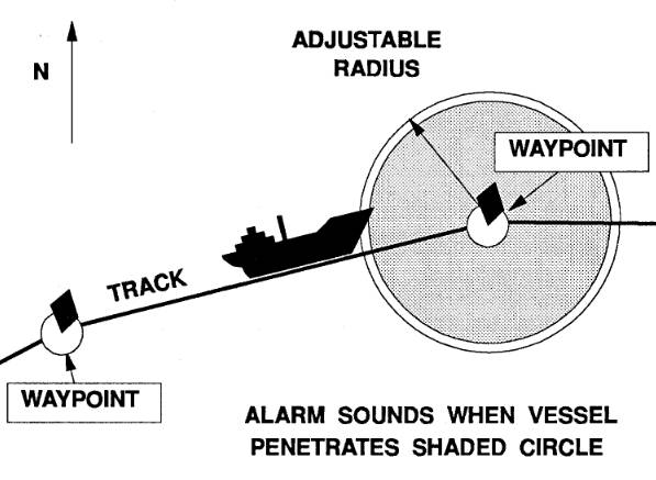
Arrival Alarm
An arrival alarm can be programmed to sound whenever the vessel passes within a user-defined distance of the next waypoint in sequence. Figure 3 illustrates the arrival alarm. The arrival alarm will sound whenever the vessel penetrates the shaded area. The alarm can be turned off manually and, on some models, will automatically shut off whenever the vessel exits the shaded area in Figure 3. Arrival alarms are useful in circumstances of bad weather or otherwise restricted visibility to alert watch-standers to be particularly vigilant in searching for an entrance buoy, for example. The arrival alarm may also signal the helm to reduce speed to avoid overrunning or running into the waypoint (if a physical object such as a buoy or a light structure). Incidentally, many lorans use different tones or tone patterns for the different alarms. One manufacturer, for example, uses the Morse code “A” (∙ -) for the arrival alarm.
Generally speaking, an arrival alarm would be set only for those waypoints where some action is required by the operator or crew, such as a course or speed change. When traveling towards waypoints where no operator action is required, the alarm can be disabled. This practice is desirable because it reinforces the idea that, when an alarm sounds, some action must be taken by the operator. Alarms that sound routinely have a desensitizing effect (“the cry wolf syndrome“) which could mean that a genuinely significant alarm would be overlooked or that alarms will not be set in the first place.
Arrival alarms are particularly useful in cases where a waypoint must be reached exactly, and in circumstances (e. g., reduced visibility) with a high potential for distraction. As with the XTE alarm, the arrival alarm should be set at a sufficient distance to avoid overrunning the waypoint. Upon hearing the arrival alarm, the vessel operator would normally slow down and carefully monitor the DTG and BRG indications to steer to the waypoint. A prudent navigator should use all available means (e. g., depth sounder, radar) to help locate the waypoint. If the waypoint were an entrance buoy, for example, and visibility were impaired (e. g., by fog or darkness) the operator might wish to initiate a systematic search pattern to ensure that the buoy was located prior to proceeding to the next waypoint.
Boundary (Border) Alarm
Figure 4 illustrates the border alarm. It may be thought of as the “minor image” of the XTE alarm, warning the user that the vessel is about to penetrate a “lane” of defined width between two waypoints. This could be used to warn the mariner that the vessel has entered a traffic separation lane.
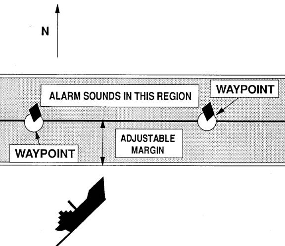
As a second illustration, this feature might be used by a commercial fisherman to avoid fishing in “illegal” fishing areas of defined dimension. These illegal areas are separated from legal zones by an imaginary line between two points of latitude/longitude or TDs. Penalties for fishing within illegal areas can be very substantial, so many commercial fishing vessels find these alarms particularly useful.
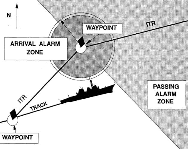
Passing Alarm
Figure 5 illustrates the passing (sometimes termed the arrival off-course) alarm. As the name implies, this alarm warns the mariner that a waypoint has been passed (technically that the vessel has passed a line perpendicular to the intended track at the waypoint) without triggering the arrival alarm.
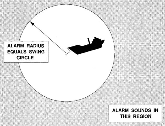
Anchor Watch
Figure 6 shows an anchor watch alarm, which might be thought of as the mirror image of the arrival alarm. The mariner defines a waypoint where the anchor is dropped, and an alarm circle sufficient to accommodate the swing circle of the vessel. Directions for how to do this vary by make and model – for some models the swing circle is preset, in other models it is adjustable. The alarm will sound whenever the vessel penetrates the shaded area – in other words whenever the anchor drags and the vessel drifts outside of a user-defined swing circle. The low power consumption of the loran ensures that the ship’s battery won’t be run down excessively if the generator is not running or not available and the loran is left on overnight so as to use the anchor watch.
Overall, an anchor watch is a desirable feature. But, it is important to have a realistic appreciation of the limitations of this feature. First, an anchor watch probably won’t be of much help in a very crowded anchorage, where the swing circles of other vessels are just boat lengths away. The repeatable accuracy of a loran may not be sufficient for this purpose. Second, unless an external land alarm is fitted, the noise of the anchor alarm may not be sufficient to wake crew sleeping some distance from the loran receiver.
Course and Speed Information
As noted above, position and timedata in the loran receiver enable the computation of course and speed estimates. In the case of loran, all course and speed estimates are referenced to motion over the ground, rather than motion relative to the water. Thus, for example, the course and speed estimates are really course-over-the ground (COG) and speed-over-the-ground (SOG).
COG and SOG information are particularly useful to the navigator, because these quantities reflect the combined effect of the vessel’s motion through the water, and the current set and drift. When navigating to a destination, the user simply alters the heading of the vessel to maintain a zero XTE, or to maintain the COG equal to the intended track, and the vessel will arrive at the chosen waypoint. Navigators should remember that the vessel’s heading (per standard compass) will generally differ from the COG, because of compass deviation and the correction or “crab” angle necessary to compensate for current (or winds aloft in the case of aircraft).
Reference to numerous owner’s manuals indicates that there is little-or-no uniformity in the nomenclature employed by various manufacturers to describe course and speed information. Moreover, the apparent definitions of these terms are generally at variance with accepted navigational nomenclature. In what follows, the course and speed features of a sample of modern lorans are summarized.
All modern lorans have the capability to display COG and SOG – or some reasonable facsimile of these quantities. According to definitions used by some manufacturers, these are incorrectly termed course-made-good (CMG) and speed-made-good (SMG) respectively – consult the owner’s manual for your set. According to traditional definitions, the COG and SOG are instantaneous values.
In the case of loran receivers, these quantities are in fact short-term average values, where the averaging period (e. g., from seconds to minutes) is adjustable by the user. Because of this time averaging, the values displayed by the receiver will lag the vessel’s actual direction and speed – e. g., the speed indication for a decelerating vessel will be overstated. “Long” averaging times (e. g., as many as 7 minutes for some models) will tend to be quite stable and accurate, provided the vessel does not alter speed. “Short” averaging times (e. g., 30 seconds) will track changes in the user’s speed more readily, but at the expense of stability.
Some receivers have the capability of determining the average course and speed (with respect to the ground) since the last waypoint – i. e., arguably the true CMG and SMG values.
Velocity Made Good (VMG)
Illustrated in slightly exaggerated form in Figure 7, velocity made good (VMG) also called velocity along route (VAR) by at least one major manufacturer, and speed of advance (SOA) by another – is a term very familiar to sailors. VMG represents the component of a vessel’s speed over the ground in the direction of the waypoint.
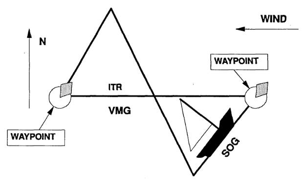
In Figure 7, a sailing vessel is travelling from the waypoint to the west to the one to the east. The bearing of this second waypoint is 090 degrees from the first. However, in this example, because the wind is assumed to be coming from the east, the vessel’s actual track must consist of a series of tacks, with the result that the actual path over the ground is a series of zig-zags shown by the dotted line. Obviously, the distance along the dotted line between the two waypoints is larger than the great circle distance shown by the solid straight line. As a consequence, the overall VMG – as measured along the solid line-would be substantially smaller than the vessel’s SOG.
In general, it can be shown that the relation between the average SOG and the VMG is equal to the cosine (cos) of the angle that the vessel’s course makes with the intended track. If, for example, the angle between the actual track and the direct course between the two waypoints were 50 degrees, and the vessel’s SOG were 6 knots, the VMG would equal 6 knots times cos(50), or approximately 3,9 knots. The sailor has a practical optimization problem to solve. Generally speaking, a sailing vessel is faster off the wind than when sailing close to the wind.
The specific relation between the wind direction and the sailboat is termed a polar diagram, and differs from vessel to vessel. But, sailing further off the wind increases the distance to be covered. The optimal course is one that maximizes the VMG. A Loran-C receiver that has the capability to display VMG could be very handy in determining the optimal course to steer. The mariner would make multiple minor adjustments on course, watching the loran closely (and allowing for averaging lags) finally setting on the course that maximizes the VMG The situation is a little more complicated than this simplified discussion suggests. See Alexander (1988) for more details.x.
Velocity Towards Destination (VTD)
The velocity towards destination (VTD) is he average component of the vessel’s SOG along the direct course to the destination. The VTD will equal the SOG provided that the vessel’s COG is exactly equal to the bearing to the next waypoint. If not, the VTD is equal to the SOG multiplied by the cosine of the angle between the COG and the bearing to the waypoint. Figure 8 illustrates the definitions of SOG, VMG, and VTD.
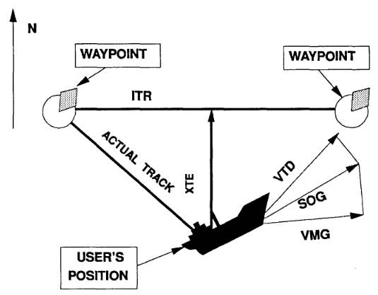
The scale has been exaggerated for clarity. In this instance, a vessel has drifted off course to the south (right) of the track between two waypoints. The operator is attempting to correct for this deviation, but the correction is insufficient because the SOG vector is not directly aligned with the bearing to the next waypoint. The VTD is the projection of the SOG vector on an axis directly oriented with the bearing to the next waypoint. The VMG is the projection of the SOG vector on an axis parallel to the original track.
In general, both VMG and VTD are less than or equal to SOG. The relation between VTD and VMG depends upon the geometry.
Time Information
Many Loran-C receivers have a built in calendar and time display. Additionally, most lorans can be used to calculate either or both of the estimated time enroute (ETE – also called TTG) or the estimated time of arrival (ETA) at the next waypoint. These quantities can be found in one of the pages of the navigational display. The TTG or ETE display will change throughout the voyage as the vessel nears the next waypoint. If the vessel slows down, the TTG or ETA will increase, if it speeds up the TTG or ETA will decrease.
Incidentally, receivers differ in how the TTG is calculated. Most receivers calculate the TTG as the distance-to-go (DTG) divided by the vessel’s SOG. This calculation will be correct only if the vessel is headed directly toward the waypoint. At least one model loran calculates the TTG as the DTG divided by the VMG, arguably a more realistic estimate.
Routes
The route capabilities of Loran-C receivers are discussed in more detail in the next chapter. However, it should be noted here that most lorans have the capability to store a route as a sequence of waypoints. Once a route is as – sembled and entered into memory, the waypoints appear in sequence, a new waypoint becomes the destination way point whenever the current destination waypoint is passed.
With some models, only one route can be stored, with others several (in some models even hundreds of) routes can be stored. The number of possible waypoints in each route may also be limited.
Voyage Planning
Most receivers can be used in a mode that facilitates voyage planning.
For example, when a sequence of waypoints is assembled into a route, the loran will display the bearing and distance from each waypoint to the next, and (on some models) the entire route distance.
Interface With Electronic Charts
As noted above, many Loran-C receivers either have “built-in” plotters or can interface with electronic charts and/or plotters. In either case, the vessel’s actual ground track can be displayed, and the waypoints along a route can be superimposed on the electronic chart of the area. This feature is convenient for many reasons. But it is particularly convenient because it facilitates thedetection of “blunders” in entering waypoint coordinates in the loran. The actual waypoints are displayed on the electronic chart and it is easy to see if the waypoint is grossly in error.
Aviation Lorans
In conceptual terms, aviation lorans are very similar to marine lorans. However, there are also some important differences in features and method of operation. (See Connes, 1990, for additional details on aircraft receivers.) Aviation Loran-C receivers are considerably more complex than marine counterparts. This added complexity is found chiefly in the “computational” and data base functions of the aviation receiver. Partially because of this additional complexity, and partially because of the respective sizes of the aviation and marine markets, aviation lorans are considerably more expensive (by as much as a factor of 10 for some makes and models) than their marine counterparts. Moreover, the annual cost of operation of the aviation is larger, because the databases (see below) have to be periodically replaced to ensure that vital navigational information is kept current.
As of this writing, only a few marine loran receivers have prestored data bases, while this feature is common on aviation loran receivers. Data available from an aircraft loran includes airport information (location, runway lengths, radio frequencies for communications, etc.), airspace information (restricted areas, terminal control areas, etc.), airway information, altitude information (e. g., minimum safe altitudes, minimum enroute altitudes, etc.) and a host of other data.
Greater computer “power” is required to access and rapidly process this information – particularly when the aircraft’s greater speed is considered. For example, it is no small task to find (quickly) and display the bearing and distance to the nearest airport – information that could be critical in the event that aprecautionary or emergency landing were necessary. As a second example, aviation receivers need to keep track (dynamically) of the aircraft’s position in relation to restricted or special – use airspace. Of course, these functions are being undertaken along with the usual signal-processing and navigation functions.
Some aviation lorans can make special purpose calculations unique to aviation (e. g., computation of density altitude, true airspeed, etc.), others compute estimates of winds aloft (the aviation equivalent of “current sailing” computations), and yet others are integrated with fuel management systems, so that the aviator can compute and update fuel reserves along with the other routine navigational bookkeeping.
There are circuitry differences between aviation and marine lorans as well, but these are less significant than the computer and software differences.
Detailed specifications for aviation loran receivers are provided in Radio Technical Commission for Aeronautics (RTCA) Document Number DO-194, as amended by the Federal Aviation Administration (FAA) Technical Standard Order TSO-C60b. This latter document contains minimum standards that must be satisfied if the loran is used for instrument flight.
Pitfalls
The capabilities of the modern Loran-C receiver are almost astounding. It is literally possible (with the right equipment) to move the vessel from the dock, enter in the required waypoints and route sequence, engage the autopilot, and do nothing thereafter until the vessel reaches the final waypoint. However, such a voyage could be very foolhardy. Built into every electronic system is the possibility of error – arising from the inherent limitations of the system, human error in programming, reliability errors, etc. These technological marvels can encourage laziness among the unwary. It is important to remember that the vessel operator or pilot in command has the ultimate responsibility for the safe passage of the vessel or aircraft.
The above caution is not intended to be a Luddite epistle. Used properly, and in conjunction with all available information, and “the ordinary practice of good seamanship,” this system offers tremendous capabilities.
The wide array of features of modern Loran-C receivers and other marine electronics greatly simplifies the job of the navigator. However, these do not relieve the navigator of the burden of systematically fixing the vessel by all available means, nor of the “ordinary practice of good seamanship.”

- Abramowitz, M., et al. “Approximate Method for RapidLoran Computation,” Navigation; Journal of the Institute of Navigation, Vol. 4, No. 1, March 1954, pp. 24-27.
- Alexander, G. “The Premier Racing Tool,” Ocean Navigator, Issue No. 20, Jul/Aug 1988, pp. 37, er seq.
- Anonymous. “Loran: Installation Pitfalls, and How Friendly Should Your Loran Be?” Practical Sailor, Vol. 11, No. 24, December 15, 1985, pp. 1, et seq.
- Anonymous. Manual on Radio Aids to Navigation, International Associationof Lighthouse Authorities, Nouvelle Adresse, 13 Rue Yvon-Villarceau 75 116, Paris, 1979.
- Appleyard, S. F. Marine Electronic Navigation. Routledge and Kegan Paul Ltd., Boston, MA, 02108, 1980.
- Ashwell, G. E., B. G. Pressey, and C. S. Fowler. The Measurement of the Phase Velocity of Ground Wave Propagation at low Frequencies Over a Land Path. Proceedings of the Institute of Electrical Engineering (London) 100 Part III, 1953.
- Bedford Institute of Oceanography. Loran-C Receiver Performance Tests, Bedford Institute of Oceanography, P. O. Box 1006, Dartmouth, NovaScotia, Canada, B2Y 4A2.
- Blizard, M. M. et al. Harbor Monitor System Final Report, CG-D-17-87, ADA 183 477, Dec. 1986, Available through the National Technical Information Service, Springfield, VA, 22161.
- Blizard, M. M., Lt. and CWO 3 D. C. Slagle. Differential Loran-C System Final litter, Draft, United States Coast Guard, January 1987.
- Blizard, M. M. and D. C. Slagle, “Loran-C West Coast Stability Study,” Proceedings of the Fourteenth Wild Goose Technical Symposium, Wild Goose Association, Bedford, MA, 1985.
- Brogdon, B., “Loran Expansion,” Ocean Navigator, Issue No. 42, SeptfOct 1991, pp. 87, et seq.
- Brogdon, W. “Loran Hook, a Little Known, Foible Explained,” Boating, August 1991, p.42.
- Brogdon, W. “Electronic Errors,” Ocean Navigator, Issue No. 40, June 1991,pp. 70, etseq.
- Brogdon, W. “Pathfinders,” American Hunter, Vol. 19, No. 7, July 1991.
- Burt, W. A., et al. Mathematical Considerations Pertaining to the Accuracy of Position, Location, and Navigation Systems, Part I, Stanford Research Institute, 1966. Available from National Technical Information Service, AD-629609, US Department of Commerce, 5825 Port Royal Road, Springfield, VA 2215 1.
- Canadian Coast Guard, Aids and Waterways Branch. A Primer on Loran-C, Ottowa, Ontario, Canada, 1981.
- Connes, K. The Loran, GPS & NAVICOMM Guide, Butterfield Press, 1990.
- Culver, C. “A New High Performance Loran Receiver,” Proceedings of the Sixteenth Annual Technical Symposium, The Wild Goose Association, 20-27 October 1987, pp. 282, et seq.
- Dahl, B. “Adopting Loran-C to Everyday Navigation,” Cruising World,May 1983,pp. 40-45.