The mastic application process within Mark III containment systems is a critical aspect of ensuring the safety and integrity of the structure. It primarily focuses on effectively sealing penetrations and joints, preventing leaks and maintaining the containment’s ability to isolate potentially hazardous materials. This process demands careful attention to detail, starting with thorough surface preparation. Surfaces must be cleaned and primed to ensure optimal adhesion of the mastic, creating a strong bond that resists degradation and prevents leaks over time.
The effectiveness of epoxy mastic in Mark III containment systems relies on proper application techniques and material selection. Factors such as temperature, humidity and the specific requirements of the penetration or joint must be considered during the application process. Regular inspection and maintenance of the mastic are essential to ensure its long-term effectiveness in preventing leaks and preserving the safety and reliability of the containment system.
Mastic Application
General Principle
The epoxy mastic has two key functions:
- Structural function in the behavior of the containment system as it secures the panel on the inner hull after polymerization.
- Smoothing function, due to its elastic behavior before polymerization, which allows to compensate the local deflection of the inner hull.
The epoxy mastic is made of two components, resin and hardener, mixed together in a predetermined ratio, at the time of use. After mixing, (mixing machine) the epoxy mastic has a short life-time before curing; therefore the installation of the panel has to be completed before expiry of the cure time. This life-time is mainly function of the temperature. Cure time is a direct function to the ambient temperature.
Epoxy Mastic Depositing Principle
Mastic is deposited on the bottom of the panels or on the inner hull in shape of patches or bead by means of epoxy mixing machine.
The size and the shape of the epoxy mastic beads and patches will depend on the flatness of the steel plating as also of the degree of smoothness required for the installation of insulating panels.
The general criteria of mastic depositing is to obtain a sufficient contact area of about 25 % and 17 % of the bonded surface, depending of the panel location (higher loaded areas or normal areas) to avoid high shear stress.
For the bead depositing, two areas will be considered. See Figure 1.
- The high loaded area.
- The normal loaded area.
The limit between the two areas is function of the vessel and also of the size and geometry of the tank. Usually for tanks no 2, 3 and 4 the limit is at the level of the top of lower chamfer, for the tank 1, the limit is at mid low chamfer level.
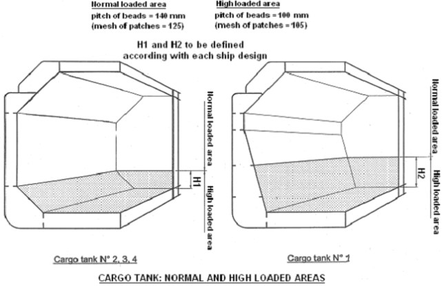
For high loaded area, the pitch of bead is about 100 mm and the mesh of patches about 105 mm.
For normally loaded area, the pitch of bead is about 140 mm and the mesh of patches about 125 mm.
For all panels, the epoxy beads and patches will be reinforced on the border.
See Figures 2 and 3 for typical beads configurations.
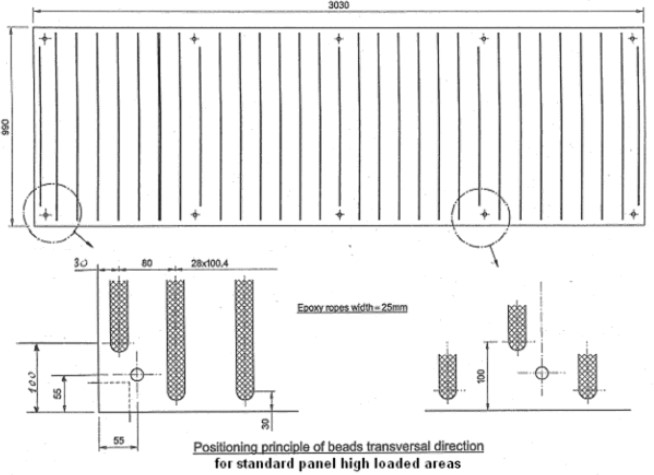
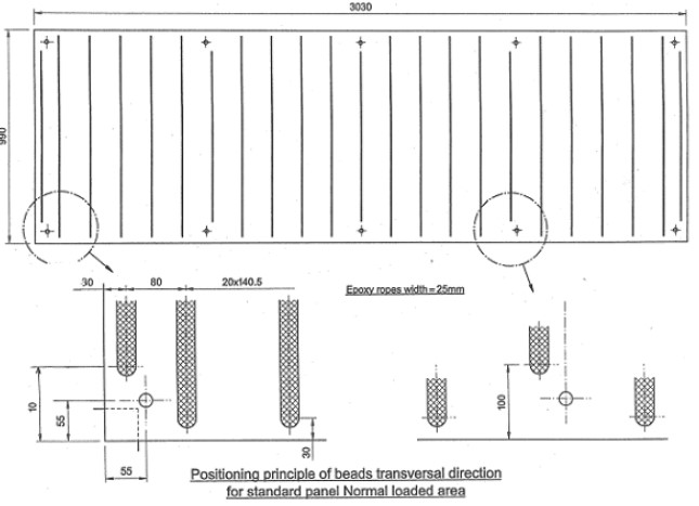
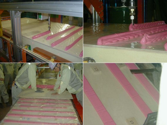
Figure 4 is photograph of panels with epoxy beads.
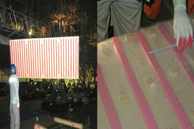
Figure 5 is a typical patch configuration.
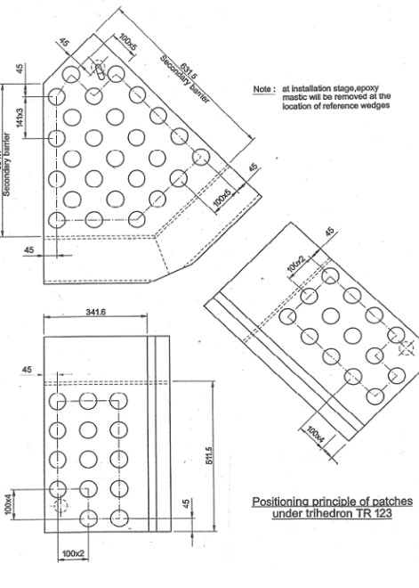
Usually, the flat panels and the two-way corner panels are fitted with beads. Patches are usually reserved to the three ways corner panels or where accessibility is restricted.
Application of Resin Beads and Patches
The size and the shape of the resin bead to be applied on the panels will be determined according to the thickness of the reference wedges resulting from the correction program (see determination of the reference surface).
The section of the beads and volume of patches given below are calculated by adding to the net value, 15 % of margin for barrel shape effect and local deformation not taken in account during dz measurement.
Actually 6 mm height margin of beads and patches are required at depositing stage in order to ensure the bearing of the panel in case of hollow Basic Elements of Boat Hull Designdeformation of the inner hull plating between dz measurement points. See table below.
| Various Types of Ropes | |||
|---|---|---|---|
| GAP “g” mm | TYPE | RESIN BEAD WIDTH 25 mm (Section mm2) | RESIN PATCH DIA : 60 mm (Volume cm3) |
| g < 7 | C1 | 200 | 23 |
| 7 < g < 12 | C2 | 350 | 40 |
| 12 < g < 15 | C3 | 430 | 50 |
| 15 < g < 20 | C4 | 580 | 65 |
| 20 < g < 25 | C5 | 720 | 80 |
| g > 25 | – | To be determined by test depending of “g”- | |
1) APPLICATION TIME
The curing time of the mastic depends on the tank temperature and can also depend of epoxy machine type.
Curing time are given by the epoxy manufacturer curing time curves. Some test to confirm these date may be carried out.
2) BEADS AND PATCHES
For insulating panels, beads or patches can be used but depending of the shape of the panels, the thickness of the epoxy mastic to be applied and the panel handling system, patches can be more appropriate.
Because of the three-dimension shape of the trihedrons, patches will be deposited instead of beads.
Because patches have compact shape (compare to beads), they allow thicker compensation of hull deflection and then will be usually used when g > 25 mm.
In normal cases, beads will be used because due to automated depositing machine, it takes less time to deposit beads and the regularity of deposit is more uniform.
However, when using manual depositing, patches are used as it is easier to control the regularity of shape of patches.
Depositing Procedure
The application of resin beads and patches on panel will be achieved manually or automatically by means of epoxy mixing/dispensing machine.
The machine includes:
- Two feed pumps.
- The metering unit made of two metering pumps.
- The mixing unit feeding the depositing nozzle.
- The automation unit controlling the feeding pumps, the metering pumps, the feeding and position of the depositing nozzle.
Figure 6 is the drawing of a depositing machine.
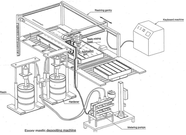
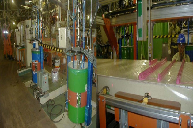
Figure 7 is a photograph of a depositing machine.
Mastic Procedure Qualification Test
A mastic procedure qualification test will be carried out before stating the insulation work. This MPQT will define the following parameters.
- Specification of the mastic given by maker:
- color;
- density;
- mixing ratio;
- pot life;
- open time;
- curing time.
- Parameters, which fix the type and size of epoxy mastic beads and patches:
- nozzle;
- shape and height;
- shape and height;
- flow rate;
- temperature.
Checking Operations at Application Time
1) EVERY DAY PRIOR STARTING PRODUCTION
Dosing condition is to be checked independently for resin and hardener by weight or volume.
2) EVERY DAY PRIOR STARTING PRODUCTION AND AT EACH EXCHANGE OF COMPONENT DRUM
Mixing process is to be checked visually by the homogeneous color of a crushed bead. No detection of veining (tiger strips) to be detected.
Dosing and mixing will be checked:
- By keeping one bead (1 meter long) at ambient temperature during 24 h and by checking proper curing.
- By keeping a mastic sample in a standard oven at 110 °C during 10 minutes and checking the normal hardness (hardness value is to be confirmed by the manufacturer). Oven test positive result is not a guarantee of good mixing but negative result is a certainty of bad mixing. It is carried out to keep from completely 24 hours of panel installation whilst ambient temperature cure sample is verified.
3) AT DEPOSITING STAGE
The proper function of the machine will be checked at regular intervals. At random and at least every hour, the characteristics of the resin beads or patches will be checked from sample taken directly from the machine.
Control will include:
- Mixing ratio between resin and hardener will be checked by the consistency of the color. A homogeneous variation of the color is the result of an incorrect dosing.
- Checking of shape and size of resin beads and patches by measuring templates.
- For each type of panel checking of right positioning of bead and patches.
4) DURING PANEL INSTALLATION
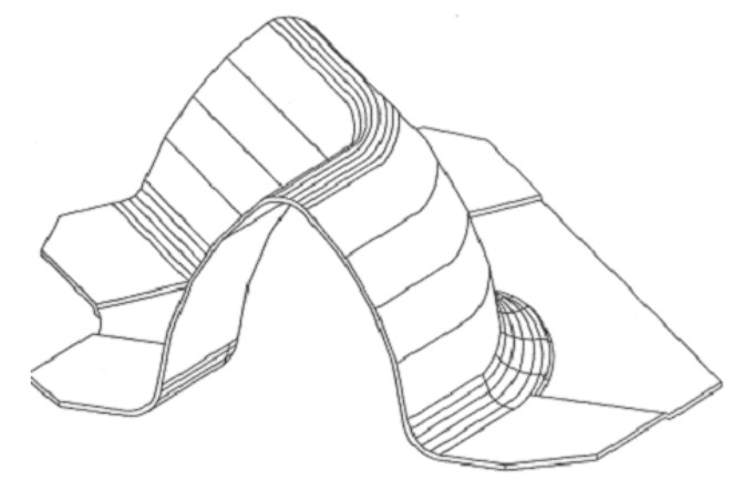
At the time of the reference surface determination, a drawing showing the type of epoxy bead/patches for each panel on a bulkhead was issued. This drawing is to be distributed to the workers in charge of the mastic application and in charge of panel installation. See Figure 8.
The type of beads/patches should be marked on the bottom of the panels and also on the inner hull to allow the installation worker to cross check the adequacy of the beads/patches.
Read also: Best Practices for Gas Tank Installation and Cargo Tank Insulation
Any wrong beads/patches should be removed and new beads/patches applied.
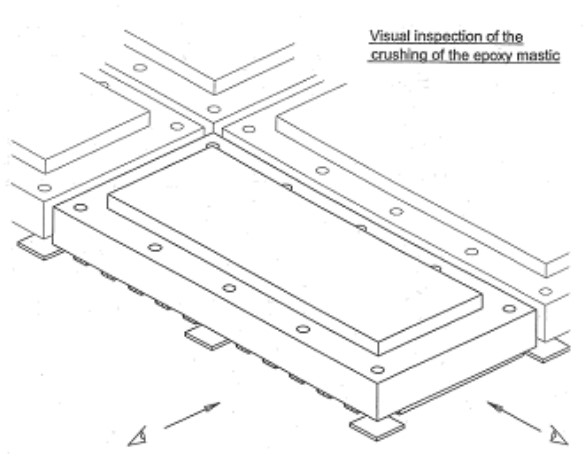
After installation of a panel it should be checked that the mastic beads/patches are well crushed by checking visually the panel visible sides. See Figures 9 and 10.
Any panel out of tolerance will be removed and re-installed properly.

