In the realm of liquefied natural gas (LNG) storage, the atmosphere within the tank and the properties of the materials used play crucial roles in ensuring safety and efficiency. Understanding the fundamental principles governing these factors is essential for engineers, operators, and stakeholders involved in LNG infrastructure.
This guide delves into the intricate interplay between LNG tank atmosphere and material properties, providing valuable insights to optimize storage facilities and mitigate risks effectively.
Principles of Tank Atmospheres
Reference: SIGTTO “LNG Shipping Suggested Competency Standards”, Section:
Know the definitions relating to tank atmosphere:
- Flammability range;
- UEL;
- LEL;
Flammable range. The term flammable range covers the area in which a mixture of gas (of a flammable substance) and air can support combustion.
Lower flammable limit (LFL) and upper flammable limit (UFL).
The limits of flammable range of a substance, is the range between the minimum and maximum concentration of vapour(% by volume) in air that forms a flammable (or explosive) mixture. These terms are usually abbreviated to LFL and UFL.
The effect of increasing the amount of O2 to a flammable mixture. Increasing the amount of O2 within an already flammable mixture causes the flammable range to increase.
For example, in the case of Methane and referring to Figure 1:
- At 14 % O2, the flammable range is approx. 2 % – 6 % (i. e. LFL = 2 %, UFL = 6 %);
- At 20 % O2, the flammable range is approx. 2 % – 12 % (i. e. LFL = 2 %, UFL = 12 %).
If the O2 level was to increase past the value of 21 %, the flammable range would continue to broaden.
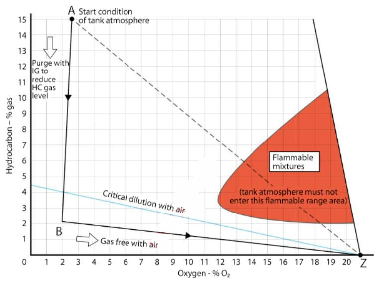
The effect of decreasing the amount of O2 to a flammable mixture. Reducing the amount of O2 available reduces the Flammability, Explosion and other Hazards of Liquefied Gasflammable range, until a point at around 12 % O2 where the gas/air mixture becomes non flammable (inert).
Critical dilution. The flammable range diagram can be used to graphically illustrate the correct gas freeing procedures, where it is important to avoid the flammable range area.
If, in Figure 1, we assume that a tank containing hydrocarbons is represented by point A (15 % HC Gas and 3 % O2), if the tank were to be gas-freed directly with air, the make up of the tank atmosphere will pass along line AZ to the gas-free position labelled Z. In following this path, the atmosphere will pass through the flammable range.
The flammable range can be avoided by:
- Initially purging the tank with IG, so that the make up of the tank atmosphere would pass along line AB to point B.
- At Point B, gas freeing by introducing air, which would result in the make up of the tank atmosphere passing along line BZ to the gas free position at point Z.
Properties of Materials
Reference: SIGTTO “LNG Shipping Suggested Competency Standards”, Section:
1 Have an awareness of the materials that are used in the construction of LNG carriers and their properties which make them suitable for use:
- Brittleness;
- Co-efficient of expansion.
2 Know and understand the materials that are used in the construction of LNG carriers:
- Where individual materials are used;
- Repair methods.
Brittleness
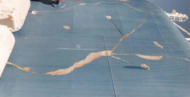
If LNG is spilled on to a steel cargo deck, or over the side of a ship constructed of mild steel, it will cool the steel down to a temperature well below the temperature of the liquid by evaporation and thermal cooling. For LNG spillages this can be catastrophic as it takes only a small subsequent blow when brittle to result in fracture of the ship’s hull or deck.
Plain carbon steel changes from a ductile state at +30 °C to a brittle state at approximately minus 50 °C (-50 °C). This precludes its use for areas that are likely to come in contact with LNG.
Materials that do not change from a ductile to a brittle state as the temperature is lowered have been used in cryogenic situations, e. g. Invar (36 % nickel-iron alloy), austenitic stainless steel, 9 % nickel steel and some aluminium alloys such as 5083 alloy. All of these materials behave in a ductile manner at minus 161,5 °C (-161.5 °C) so there is only a negligible chance of a brittle fracture developing.
To avoid the possibility of brittle fracture occurring, measures must be taken to ensure that LNG does not come in contact with the steel structure of the ship.
The manifold area is equipped with stainless steel drip trays that drain the cargo away from the ship’s deck and sides, combined with a water wash-down (water curtain) in the event of spillage. The fire main must be available during cargo operations.
Fire hoses must be ready for immediate use at each cargo dome to deal with any small leakages that may develop at valves. Flanges and permanent drip trays are fitted underneath the items most likely to leak.
Read also: Cargo Containment Systems of LPG and LNG
Damage from multiple cargo tank failures because of brittle fracture caused by exposure to cryogenic liquid or fire-induced damage to foam insulation has been evaluated and, while possible under certain conditions, is not likely to involve multiple cargo tanks for any single incident. An event such as this would not be expected to greatly increase (~20 % – 30 %) the overall fire size or hazard, but is likely to increase the duration of the fire.
If a leak or spill of LNG occurs, the liquid will vaporise. This vaporisation has two distinct phases. During the first phase there will be a violent rate of “boiling” as the heat for vaporisation is taken from the immediate surroundings and the spill itself. After this phase the cold vaporised gas insulates the liquid surface, causing the rate of evaporation to stabilise (or reduce) in proportion to the ratio of heat transfer from the surrounding areas to the LNG.
Coefficient of expansion
The coefficient of thermal expansion describes how the size of an object changes with a change in temperature. The materials used on an LNGC are suitable for the extreme range of temperatures encountered. This includes the Piping System of pressure vessels on gas tankerspiping arrangements and cargo tanks.
Piping. Piping is constructed from stainless steel as its suitability for cryogenic use is well established. The standard grade of wrought stainless steel for general cryogenic applications is type 304L, but various additional grades have been specified, including 304LN and 316LN. An important feature of the austenitic stainless steels is their excellent weldability and resistance to corrosion.
Tanks – use of “nickel steel”. 5 % nickel steels were developed as a less expensive option to the 9 % ones,while still retaining a good impact resistance at low temperatures.The tensile strength is, however,lower than that of the 9 % nickel steels.
9 % nickel steels provide a combination of properties at a reasonable price. Their excellent low temperature impact properties are the result of a fine grained structure of tough nickel-ferrite. Small amounts of stable austenite formed by tempering improves impact resistance after heat treatment.
Both 5 % and 9 % nickel steels have very good “weldability” and are welded with shielded metal arc welding (SMAW) with covered electrodes.
Cargo tank materials. The cargo tank materials used are determined by the minimum service temperature and by their compatibility with the cargoes to be carried.
The most important property for selection of cargo tank materials is their suitability for the low temperature of LNG (i. e. minus 161,5 °C (-161,5 °C)). Most metals and alloys become brittle below a certain temperature and this influences the material selection for LNGCs.
Insulation
Thermal insulation is installed around the cargo tanks to:
- Minimise heat ingress into cargo tanks and so minimise cargo boil-off.
- Protect the ship structure around cargo tanks from the effects of the cryogenic temperatures of LNG.
The main properties that any insulation material used must have are:
- Low thermal conductivity;
- Non-flammable or self-extinguishing;
- Load bearing for membrane ships;
- Moisture resistant;
- Non-toxic;
- Tolerance to mechanical damage;
- Lightweight;
- Not penetrable by liquid or vapor.
Vapour sealing to prevent ingress of water and water vapour into the insulating material is very important. Not only can ingress of moisture result in a loss of insulation efficiency but, in the worst cases of condensation and freezing, extensive damage to the insulation or membrane can occur. Therefore, humidity must be kept as low as possible in interbarrier, insulation and hold spaces.

Thermal insulation application depends on the design of the containment system.
Repair methods
It may be possible to carry out repairs on board the LNGC. However, in most cases, repairs will be carried out in dry-dock or alongside, with shore based technical assistance. Repair methods will vary by tank construction/type.
Some older 9 % nickel steel tanks have shown significant amounts of cracking after years of service. The cracks can be repaired by removal of the affected section, following manufacturer’s recommendation and welding in new material. After any modification, a tightness test must be conducted. This may involve a global test or a helium leakage test.

Aluminium tanks present different cracking problems to those of membrane tanks. The attachment of an aluminium tank to a steel cylinder is a difficult process (due to the metals involved) and cracks may well develop where those materials are joined.
There is little reported on repairs to cracks of the Moss Sphere type.