Because of the nature of the substances, handling liquefied gas will inevitably create potential hazards (explosion, ignition, human health and etc).
- Health Hazards
- Respiration
- Toxicity
- Exposure and Short Term Exposure Limits for Gases
- Medical Treatment
- Symptoms of Asphyxia
- Flammability and Explosion
- Explosion
- Flammable Range
- Flashpoint
- Auto-ignition
- Fire Triangle – Advanced
- Vapour Cloud
- O2 Concentration and Inerting
- Effect of Reducing the O2 Content
- Reducing the Hydrocarbon Gas (% Gas) Levels in a Tank
- Summary of Gas Freeing
- Sources of Ignition
- Smoking
- Hot and Cold Work
- Non-Sparking Tools
- Static Electricity
- Bonding
However, a sound understanding of the characteristics of the gases coupled with a rigorous approach to the permit systems and procedures will mean that incidents are unlikely to occur.
This article reviews some of the possible risks and outcomes of close contact or poor handling, providing advice on management of symptoms or circumstance as appropriate.
Health Hazards
In the event of an incident, personnel engaged in the handling of liquefied gases may be exposed to the liquid or its vapour This represents a Risk Assessment in the Liquefied Natural Gas Bunkering Operations, Hazard Identificationrisk to health, the degree of which will depend on the particular liquefied gas.
All liquefied gases are volatile and precautions must be taken to avoid exposure to their vapours.
Respiration
When breathing, you inhale oxygen (O2) into the body and exhale carbon dioxide (CO2) out. We normally breathe at a rate of between 12-20 times per minute, taking in about 500-700 ml of air each time.
The exchange of the gases O2 and CO2 in the lungs is called “respiration”.
1 Fresh Air
Fresh air contains the following three gases in the approximate quantities shown:
- Nitrogen (N2) – 78 %.
- Oxygen (O2) – 21 %.
- Carbon Dioxide and other gases (CO2) – 1 %.
If breathing stops, causing a build-up of CO2 and a deprivation of O2, you could suffer brain damage or death.

To breathe, the human body requires air containing 20,9 % oxygen. Air containing oxygen concentrations below that figure are unsafe as asphyxia would result from exposure to it.
2 Oxygen Deficiency
Oxygen deficiency will result if oxygen is displaced from the air by cargo vapours or by inert gases, such as nitrogen.
If oxygen has been displaced by cargo vapour, in addition to asphyxia there may be further complications from the effects of narcotic, irritant and/or toxic vapours.
The symptoms of oxygen deficiency are mental confusion, loss of muscle movement and unconsciousness. Ultimately, you will stop breathing.
The symptoms of hydrocarbon narcosis follow a sequence:
- Sensations become blunted.
- Skin becomes numb or insensitive.
- Movements are clumsy.
- An excitable and/or emotional phase occurs.
Toxicity
The following chemical gases are all toxic:
- Vinyl chloride monomer (VCM);
- Ammonia;
- Butadiene;
- Chlorine;
- Ethylene oxide;
- Propylene oxide;
- Inert gas (if it contains carbon monoxide).
Most of these toxic gases, with the exception of VCM, are also irritants. Irritants damage the body tissues by direct contact and the first warning may be pain in the eyes, nose, throat and air passages. Some of these irritants may also cause damage to the skin.
Toxicity is the measure of how toxic or poisonous something is. Some toxic substances can be extremely harmful, causing illness and even death when in high concentrations. However, many are only irritants that need careful protection and procedures.
Toxicity is often quoted in terms of its Threshold Limit Value (TLV). This is the average concentration under which most people can work consistently for eight hours per day, based on a 40-hour week, with no harmful effects. Gas or vapour presence is expressed in parts per million (ppm). It should be noted that in the UK the TLV notation has been changed to Workplace Exposure Limit (WEL) to simplify the understanding.
STEL (Short Term Exposure Limit) is the average concentration that can be tolerated for a 15 min exposure, with a maximum of 4 such exposures per 24-hour period. There must be at least 1 hour of rest period between each exposure. STEL values are not normally quoted for gases that are highly toxic.
As all liquefied gases are volatile they rapidly evaporate when spilt onto the skin, taking heat for the vaporisation from the surrounding body tissue. This can lead to extremely severe “cold burns”.
| Table 1. Health Data, Vapours/Gases | |||||
|---|---|---|---|---|---|
| Asphyxiant | Narcotic | Toxic | Irritant | TLV–TWA (ppm) A-Asphyxiant | |
| LNG | * | A | |||
| LPG | * | * | A | ||
| Methane | A | ||||
| Ethane | * | A | |||
| Propane | * | A | |||
| Butane | * | * | 600 | ||
| Ethylene | * | * | A | ||
| Propylene | * | * | A | ||
| Butylene | * | * | 800 | ||
| Butadiene | * | * | * | 2 | |
| VCM | * | * | * | 1 | |
| Ammonia | * | * | * | 25 | |
| Chlorine | * | * | * | 0,5 | |
| Ethylene Oxide | * | * | * | * | 1 |
| Propylene Oxide | * | * | * | * | 2 |
| Nitrogen | * | A | |||
Exposure and Short Term Exposure Limits for Gases
| Table 2. Exposure Limits | ||
|---|---|---|
| Tlv/wel | Stel | |
| Ammonia | 25 ppm | 35 ppm |
| Butadiene, inhibited | 2 ppm | 5 ppm |
| Butane | 600 ppm | |
| Butylene | No occupational exposure limits established | |
| Chlorine | 0,5 ppm | |
| Ethane | 1 000 ppm | |
| Ethylene | 1 000 ppm | |
| Methane | 1 000 ppm | |
| Propane | 1 000 ppm | |
| Propylene | 1 000 ppm | |
| Propylene oxide | 2 ppm | |
| Vinyl chloride monomer | 1 ppm | 5 ppm |
| Benzene | 0,5 ppm | 2,5 ppm |
| Carbon monoxide | 25 ppm | |
| Hydrogen sulphide (h2s) | 10 ppm | 15 ppm |
| Sulphur dioxide | 2 ppm | |
These figures can change because of legislation. You should always check for the latest recommendations.
Medical Treatment
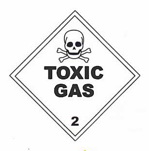
Professional medical treatment should always be sought where casualties have been overcome by toxic and/or irritant vapours. In such situations it is extremely important to label the patient, as they may be unconscious or unable to control their own speech.
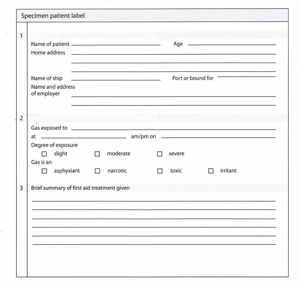
Correct labelling is important to medical authorities, who will need as detailed a report as possible to allow for rapid detection of a particular gas or vapour, as there are thousands of possibilities.
1 Cold Burn or Frostbite
A refrigerated gas at very cold temperatures has severe effects when in contact with skin. The symptoms of a cold burn are similar to those for a thermal burn. The main symptom is severe pain in the affected area, often accompanied by confusion, agitation, fainting, acceleration of the pulse and rapid breathing. If the area of the burn is large shock is likely to develop.
The symptoms of a cold burn are similar to a hot burn.
When treating a cold burn, the affected part should be warmed by hand or woollen material. Massage should be prevented as this will cause flesh wounds. Should a finger or hand be burned, the casualty should hold their hand under their armpit. The affected part should then be placed in warm water, at about 42 °C. Warming may take from 15-60 minutes. If this is not practicable, then the casualty should be wrapped in blankets and circulation should be allowed to re-establish itself naturally. Pain killers or morphine may be required to control pain during warming.
Read also: Properties and hazards of shipping LNG, LPG
If it is possible, the casualty should be encouraged to exercise the affected part while it is being warmed. Blisters should never be cut or opened, nor should clothing be removed if it is adhering firmly. The entire affected area should be covered with sterile dressings. In all other ways, the treatment should be as for thermal burns.
Chemical burns can be caused by:
- ammonia,
- chlorine,
- ethylene oxide,
- propylene oxide.
In addition, VCM and chlorine are both toxic through skin absorption. Symptoms for chemical burns are similar to thermal and cold burns, but they are particularly damaging to the eyes. The affected area should be washed thoroughly with fresh running water at the ship’s emergency showers for 10-15 minutes. After this, the affected area should be covered with a sterile dressing. Subsequent treatment is as for thermal burns.
If you require further information please consult: the IMO Medical First Aid Guide for Use in Accidents lnvolving Dangerous Goods.
| Table 3. Health Data, Liquids | ||||
|---|---|---|---|---|
| Irritant | Cold burn | Chemical burn | Skin absorption | |
| LNG | * | |||
| LPG | * | |||
| Methane | * | |||
| Ethane | * | |||
| Propane | * | |||
| Butane | * | |||
| Ethylene | * | |||
| Propylene | * | |||
| Butylene | * | |||
| Butadiene | * | * | ||
| VCM | * | * | ||
| Ammonia | * | * | * | |
| Chlorine | * | * | * | * |
| Ethylene Oxide | * | * | * | |
| Propylene Oxide | * | * | ||
| Nitrogen | * | |||
Symptoms of Asphyxia
The symptoms of asphyxia shown in table 4 are from gases such as LNG, LPG, ethane or flue gases.
To treat asphyxia, remove the casualty from exposure to the gas and, if necessary, apply artificial respiration and cardiac massage. Where possible, and if breathing is laboured, oxygen should be given. Clothing must be loosened and, if the casualty is conscious, drinks should be supplied. The casualty should rest while medical advice is sought.
| Table 4. Symptoms and Treatment of Asphyxia | |
|---|---|
| Asphixiants | LNG, LPG, Methane, Ethane, Propane, Butane, Nitrogen, Flue Gas |
| Symptoms | Increased rate and depth of respiration |
| Cyanosis (blueness of the skin) | |
| Strenuous breathing (with a snoring sound) | |
| Loss of consciousness | |
| Paralysis of respiratory centre | |
| Treatment | Remove from exposure |
| Apply artificial respiration if required | |
| Apply external cardiac massage | |
| Loosen clothing | |
| Give oxygen if cyanotic (blue coloured to the face) or if breathing is laboured | |
| Keep at rest | |
| Unless symptoms are minor seek medical advice | |
Flammability and Explosion
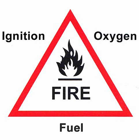
Combustion is a chemical reaction in which a flammable vapour or gas combines with oxygen, in the correct proportions and in the presence of a source of ignition, to produce under normal conditions carbon dioxide, water and heat.
The three conditions necessary for combustion to take place are:
- A source of fuel;
- The presence of oxygen;
- A means of ignition.
Flammable vapour to oxygen and/or air must be in approximately the correct proportions (i. e. within the flammable range) for combustion to succeed.
Explosion
The difference between combustion and explosion is the time difference in the rate of reaction (see picture 3).
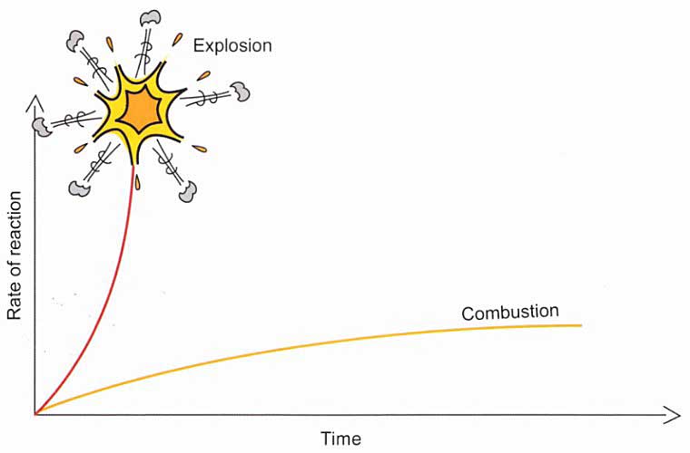
1 Combustion
In combustion, the rate of energy released is balanced by the rate at which the energy dissipates to the surroundings. The result is a combustive reaction that proceeds smoothly.
2 Explosions
Explosions are more likely to occur in confined spaces where the products of the combustion and heat are not removed from the reaction zone. The temperature continues to rise in these circumstances and, as the system is confined, the pressure will rise too. The rate of reaction will increase exponentially until all reactants are consumed.
In confined/enclosed spaces, or any space where the air supply is restricted, a fire will eventually extinguish itself as the oxygen is consumed and the atmosphere becomes inert.
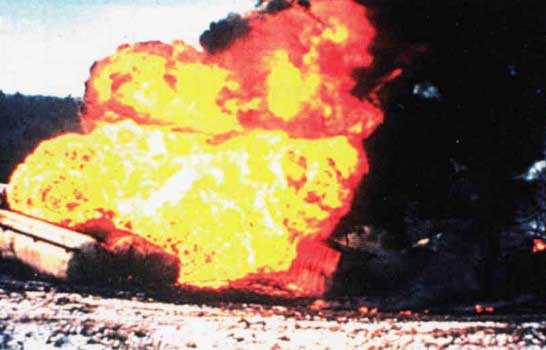
3 BLEVE
BLEVE, pronounced ‘blevy’, is an acronym for “Boiling Liquid Expanding Vapour Explosion”. This is a type of explosion that can occur when a pressure vessel containing a pressurised liquid is ruptured. Such explosions can be extremely hazardous.
This phenomenon is not commonly encountered and is unlikely in ship containment. It can arise when flammable vapour is suddenly released from a pressure vessel in the presence of a source of ignition. The energy change under these circumstances can be sudden and highly explosive, with considerable destructive force.
A BLEVE can occur in a pressure vessel that stores a substance that is usually a gas at atmospheric pressure but is a liquid when pressurised (for example, LPG). The substance will be stored in a partly liquid form, with gaseous vapour above the liquid filling the remainder of the container.
If the pressure vessel is ruptured, for reasons such as corrosion or failure under pressure, the vapour portion may rapidly leak. This drops the pressure inside the container and releases a wave of overpressure from the point of rupture. The sudden drop in pressure inside the pressure vessel causes violent boiling of the liquid, which rapidly liberates large amounts of vapour in the process.
The pressure of this vapour can be extremely high, causing a second and much more significant wave of overpressure (i. e., an explosion), which may completely destroy the pressure vessel and project it as shrapnel over the surrounding area or even project the whole cylinder for many hundreds of metres.
A BLEVE does not require a flammable substance and so is not usually considered a type of chemical explosion. However, if the substance involved is flammable, it is likely that the resulting cloud will ignite after the BLEVE proper has occurred, forming a fireball and possibly a fuel-air explosion. BLEVES can also be caused by an external fire near the storage vessel, causing the contents to heat and pressure to build-up.
In the event that a pressurised gas cylinder is venting, BLEVES can be avoided by cooling the cylinder with water or foam, taking care not to extinguish the flame until the cylinder is empty or the leak is plugged.
Flammable Range
The term “flammable range” refers to the proportion of flammable gas to air necessary for combustion.
The limit of flammable range is the difference between the minimum and maximum concentration of vapour (% by volume) in the air that forms a flammable mixture.
The flammable range of some chemicals is greater than for many petroleum’s.
The upper and lower limits of the flammable range for a substance are usually abbreviated to LFL (Lower Flammable Limit) and UFL (Upper Flammable Limit).
LFL and UFL are synonymous with LEL and UEL i. e. Lower and Upper Explosive Limits.
All of the liquefied gases, with the exception of chlorine, are flammable. Hovewer, the values of the flammable range are variable and depend on the particular vapour. Ammonia, with a flammable range of 16-25 % Volume in air, is not listed as a flammable substance in the IGC Code as it requires substantial pressure to be able to ignite.
The flammable range of a vapour widens dramatically in the presence of pure oxygen. The lower flammable limit is little affected but the upper flammable limit is considerably raised.
| Table 5. Flammability Properties at Atmospheric Pressure | |||
|---|---|---|---|
| Flammable range (% vol) | |||
| In air | In oxygen | ||
| Propane | 2,1-9,5 | 2,1-55,0 | |
| n-Butane | 1,8-8,5 | 1,8-49,0 | |
| Flash point (°C) | Flammable range (% by volume) | Auto ignition temperature (°C) | |
| Methane | -175 | 5,3-14 | 595 |
| Ethane | -125 | 3,1-12,5 | 510 |
| Propane | -105 | 2,1-9,5 | 468 |
| n-Butane | -60 | 1,8-8,5 | 365 |
| i-Butane | 1,8-8,5 | 500 | |
| Ethylene | -150 | 3-32 | 453 |
| Propylene | -108 | 2-11,1 | 458 |
| n-Butylene | -80 | 1,6-9,3 | 440 |
| i-Butylene | 1,8-8,8 | 465 | |
| Butadiene | -60 | 2-12,6 | 418 |
| Vinyl Chloride Monomer | -78 | 4-33 | 472 |
| Ethylene Oxide | -18 | 3-100 | 429 |
| Propylene Oxide | -37 | 2,8-37 | 465 |
| Ammonia | -57 | 16-25 | 615 |
| Chlorine | Not flammable | ||
| Isoprene | -50 | 1,0-9,7 | 220 |
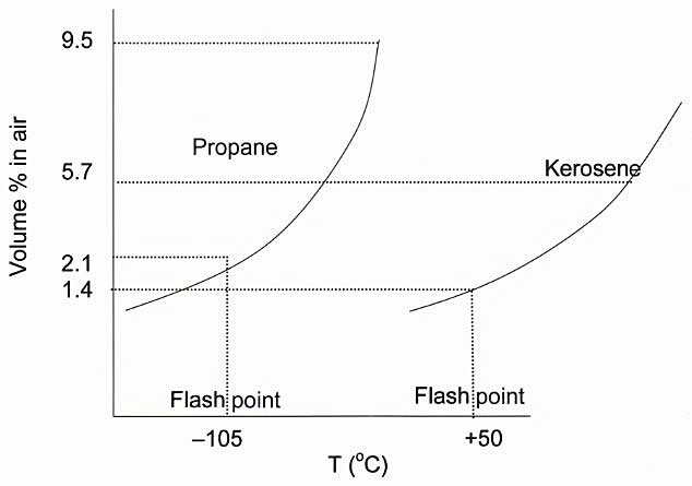
Flashpoint
The flashpoint of a liquid is the lowest temperature at which a liquid gives off enough vapour to form a flammable mixture with air that is capable of igniting from a spark or flame. The flashpoint for a liquid is related to the vapour pressure and boiling point of that liquid, and corresponds to the LFL of its vapour.
ln general, high vapour pressure liquids such as LPGs have extremely low flashpoints when compared to less volatile, lower vapour pressure liquids, such as kerosene. The difference in this relationship is shown below.
1 Too lean
If a liquid is at a temperature colder than its flashpoint, there would not be enough vapour to produce a flammable mixture with air. This can lead to a mixture that is “too lean” or “too weak”.
“Too lean”. Think of a mountaineer with a butane stove. If it is very cold outside, or he is at altitude, the butane will not ignite because it is “too lean” until he warms it, usually with his hands.
Although the supply of vapour can be affected by the amount of heat applied to a liquid, a dilution of warm vapour by a breeze or wind can continue to sustain a flammable vapour in a “too weak” or “too lean” condition.
2 Over rich
When a liquid is heated above its flashpoint, there is an increase in temperature that relates to a progressive richening of the flammable mixture in air. The point above which the mixture would not theoretically ignite is termed the “Upper Flammable Limit”. If you were to continue heating the liquid above that level, you would be generating too much gas for the volume of air, and so the mixture would be termed “over-rich”.
The vapour space above a liquefied gas cargo in a tank is always over-rich because of the very high vapour pressure of this type of cargo and the consequent exclusion of air borne oxygen.
Auto-ignition
Flash Point is not the same as the ignition or auto-ignition point. This is the minimum temperature required to ignite a gas or vapour in air without a spark or flame being present. It can be an important factor with less volatile liquids that may be in contact with a heated surface above their ignition point.
It is important to ensure that vapours or waste material are never heated to their ignition point temperatures in the presence of air.
External sources of ignition include sparks and flames and, less obviously, hot compressor discharges that can bring combustibles above their auto ignition temperature without a spark or flame.
Fire Triangle – Advanced
Combustion can only take place when the following are present:
- A source of fuel;
- Oxygen;
- A source of ignition.
We can now refine this further with the following rules:
- The temperature of the liquid must be above the flashpoint.
- The mix of flammable vapour to air and/or oxygen must fall within the upper (UFL) and lower (LFL) limits for that vapour.
- The source of ignition temperature must exceed the auto ignition temperature of the vapour.
Vapour Cloud
When a liquefied gas is spilled in an open space the liquid will evaporate to produce first a large vapour cloud and then an extremely large cloud of a mixture of flammable gas and air.
For example, in the case of butane:
The resulting vapour cloud is not flammable throughout its entire volume. The cloud is sometimes referred to as a plume, and is shown as a concept in picture 7. However, reality can introduce vapour eddies and many other variables.
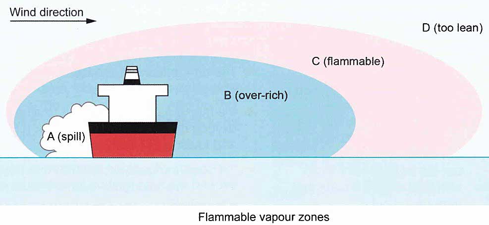
Area “B”, which is immediately above the spill area, would be non-flammable. This is because it contains too high a percentage of flammable vapour and so would be over- rich.
Area “D” would also be non-flammable because it contains too little flammable vapour and so would be too lean.
The flammable range would be somewhere between B and D, referred to as “C” in the diagram.
O2 Concentration and Inerting
Increasing the O2 concentration in a flammable mixture causes a broadening of the flammable range. Decreasing it will cause the flammable range to be narrowed.
If the oxygen concentration is reduced sufficiently the atmosphere will become non-flammable, a state referred to as inert.
Effect of Reducing the O2 Content
An atmosphere that is inert (not enough O2 to support combustion of hydrocarbons) is such when it contains less than approximately 12 % oxygen. Some other fuels can combust in less than 12 % oxygen.
On gas carriers (and other tankers), the in-tank O2 content is generally reduced to less than 2 % by volume. In some gas carriage conditions, such as for polymerisable butadiene and VCM cargoes, the practice is to reduce the O2 content of tanks to 0,1 % volume, with similarly low figures experienced in the carriage of LNG.
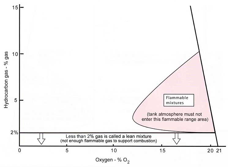
Picture 8 illustrates this concept for typical propane and butane hydrocarbon gases in mixtures with air.
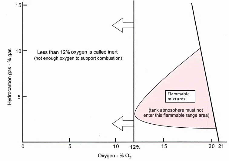
Note: Other gases would show slightly different flammable mixture areas depending on their flammable limits and the quantity of oxygen necessary to combust.
The flammable range, i. e. the pink area representing the flammable range between LFL to UFL, reduces as the oxygen content decreases. An 02 content of less than the left hand extremity of the flammable envelope (i. e. 12 %) renders the mixture inert.
If you look at the flammable area for 20,9 % O2, the LFL = 2 % GAS and the UFL = 10 % GAS.
The O2 value at which most hydrocarbon gases become inert is between 11-12 %.
Note: to allow for safety in this area, the IGC Code demands that an inert gas generating plant (if provided on board) will supply no more than 5 % O2 in the header supplying the inert gas to the tanks.
Reducing the Hydrocarbon Gas (% Gas) Levels in a Tank
If the tank contained hydrocarbons such as LPGs, these would first have to be removed. The action of purging the tank through with several volumes of inert gas will progressively reduce (dilute) the % gas lair mixture, that is “purge before gas freeing”.
After purging, to gas free a tank for entry, once the % gas level is at 2 % or less (1,6 % if possible) you can open the tank and ventilate it with air. The objective of the gas freeing operation is to ventilate the tank with fresh air until the O2 level raises to 20,9 % volume. Ventilation will be continued after this point to ensure that the O2 level remains at 20,9 %.
Conducting the gas freeing operation in this manner, by purging with inert gas until the hydrocarbon level, i. e. % gas is 2% or less and then gas freeing with fresh air to achieve an O2 level within the tank of 20,9 %, will ensure that the tank atmosphere (throughout the operation) passes as far away as possible from the “flammable mixture” area, as shown in picture 10.

Summary of Gas Freeing
Introducing air to the tank without having suppressed the hydrocarbon content of the atmosphere (by using inert gas) will cause the mixture to follow path A-Z. This is extremely hazardous. The correct method is to follow line AB and then line BZ (see picture 10).
When presented with a tank of hydrocarbon gas to gas free:
- From starting point “A” purge inert gas through the tank to the mast riser; reducing the % gas level within the tank.
Note: the instrument commonly used is the “tankscope” for “% gas” readings. Use the model of instrument suitable for operation in inert gas. - At point “B” which is 2 % gas is equivalent to 100 % of the LFL in this case, as read on an explosimeter; open the tank and commence gas freeing with air.
Note: an “explosimeter” also known as a “combustible gas indicator” will be used to monitor the % LFL. A meter such as a “Servomex” will be used to monitor % O2. - At point “Z” the atmosphere will contain 20,9 % O2 and have as 0-1 % LFL. The tank should be checked for other “trace” gases using a Dräger tube or similar apparatus. Ventilation of the tank with fresh air should continue throughout the period that the tank is open to the atmosphere.
A tank can only be entered once a gas test certificate has been completed by a competent person and an enclosed space entry permit has been issued.
Sources of Ignition
The hazards of fire and explosion on gas carriers are managed through the use of cargo handling operations that control the fuel sources such as flammable atmospheres, liquid spills or the release of vapour.
The following items are activities that present risk by providing a potential source of ignition on board.
Smoking
Smoking, and in particular the carriage of cigarette lighters or matches, is the most obvious source of ignition/naked flame/sparks and so it should always be restricted to pre-defined and approved locations.
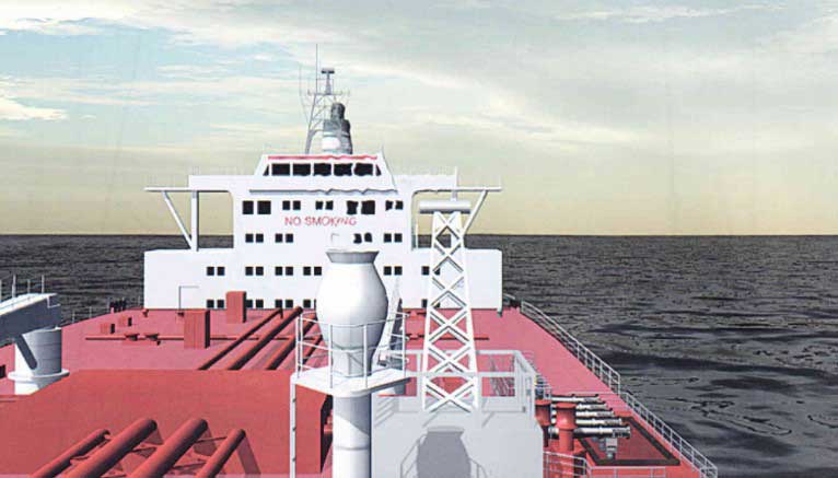
Care must be taken to enforce the regulations during cargo-handling operations, particularly when visitors who may not appreciate the nature of the cargo being handled are present.
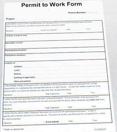
Hot and Cold Work
Hot and cold work should only be permitted under the strictly controlled conditions of a permit to work system.
During hot and cold work operations, atmospheres in areas that could become hazardous should be continuously monitored with instruments that arc capable of automatic alarm if they detect flammable
vapours.
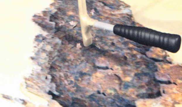
Non-Sparking Tools
The use of “safety tools” in hazardous areas often creates a false sense of security. Constructed from soft nonferrous materials, these tools are often referred to as “non-sparking”. However, fragments of steel can easily become embedded in the head, which can subsequently create a spark that renders them as dangerous as any other.
Static Electricity
Static electricity can arise when liquids or gases are pumped through pipelines at high velocity. Non-conducting liquids (static accumulators), emulsions, carbon dioxide and steam are common sources of static electricity. The generation of static generally increases with speed of flow.
A good example of static can be observed when you remove a nylon/polyester pullover or shirt.
The removal of clothing in hazardous areas, particularly in dry atmospheric conditions, can also give rise to static discharge.
Electrical instruments designed for essential use in hazardous areas should be of flameproof or intrinsically safe design. In Europe electric equipment for use in hazardous areas must be “ATEX Approved”, “ATEX” – which derives from the original working title “ATmosphere EXplosive”. This is under the EC Directive 94/9/EC that was established in 1994.
Bonding
Electrical sparks can occur between the ship and shore if the cargo connection (hose or hard arm) provides an electrical path between the ship and shore structures. The risk occurs at the point when this connection is made or separated.
A spark may be generated when connecting or separating a metallic connection between the ship and shore.
Electric current will flow through this path because of the difference in the electrolytic potential of the ship and jetty structures and the surrounding sea water. Differences that occur naturally because of the different steels or protective coatings of the two structures may be increased by an imbalance in the degree of cathodic protection applied to each.
Although the resulting difference between ship and jetty would never be more than a fraction of a volt, the electrolytic cells involved are large and electrical resistances in the ship/sea water/jetty/cargo connection circuit are small. As a result, a heavy current of many amperes may flow through the cargo connection and this current, when established or interrupted, may produce a spark.
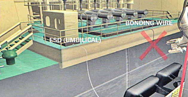
The bonding cable was traditionally connected between jetty and ship to provide an alternative path for this current. However, in practical terms, they are quite ineffective for this purpose.
The use of the bonding cable is no longer recommended. The introduction of an electrical discontinuity in the cargo connection, by means of an insulating flange or a length of electrically discontinuous hose, is effective in eliminating the cargo connection current and any resultant sparking.
For reasons of accessibility and to avoid the possibility of sparking through electromagnetic induction in the hard arm length, insulating flanges are usually located at the lower end of the outer arm of the hard arm.
For a ship/shore bonding cable to be effective it would need to be 12” diameter copper and is therefore unrealistic.