Proper tank installation and insulation requires careful attention to detail, especially when it comes to bonding and final checks. This step is vital for maintaining the integrity of the tank system and protecting personnel.
- Bonding of Steel Corner/Hardwood Key Assembly
- General
- Bonding of Hardwood Key
- Bonding of Hardwood Key Assembly Between Trihedron and Corner Panel
- Bonding Procedure Qualification Test for Hardwood Key
- Bonding of Top Bridge Pads
- General
- Bonding of Top Bridge Pads Between Flat Panels
- Bonding of Top Bridge Pad Alongside Corner Panel
- Bonding Procedure Qualification Test
- Insulation Completion – Protection and Final Check
- Fitting of Thermal Protection Strips
- Final Inspection of the Insulation
The final check after installation and insulation is equally important. A thorough final check guarantees the system’s safe and efficient operation, minimizing the risk of future problems and maximizing the lifespan of the tank.
Bonding of Steel Corner/Hardwood Key Assembly
General
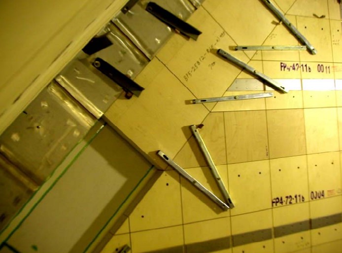
The steel corner/hardwood key assembly is installed over the secondary barrier S-triplex located at the junction of two adjacent corner panels.
Bonding of Hardwood Key
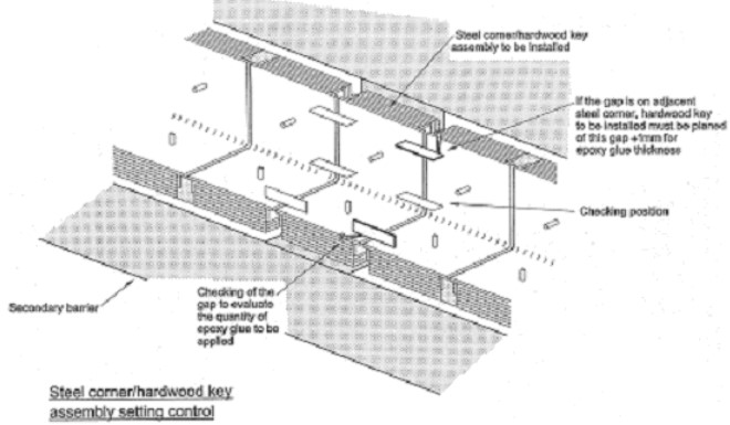
Once the curve Guidelines for Installing and Bonding Secondary Barrier TriplexS-triplex strip bonding has been checked, the appropriate steel corner hardwood key assembly is selected and placed in order to evaluate the quantity of epoxy glue to be applied and check if it is necessary to plane the back face.
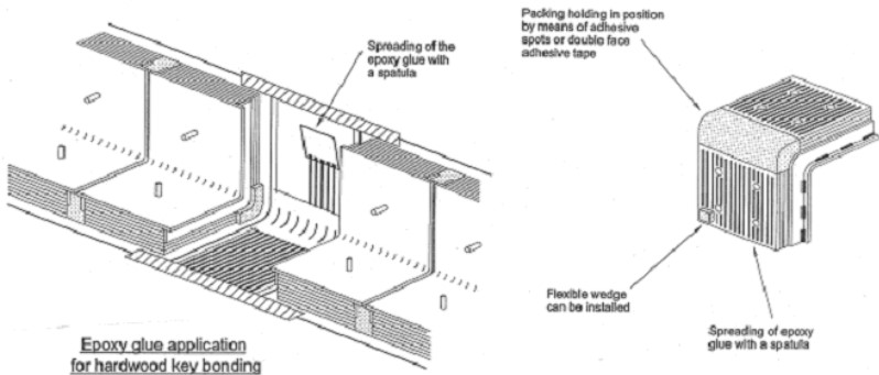
By means of a spatula, epoxy glue is spread over both hardwood key and the corresponding surface of the S-triplex strip. (See Figure 1.)
Due to the important thickness of glue to be used for the bonding of the hardwood key, a special type of epoxy glue will be used. The characteristics are the same of the one used for the triplex but it is less fluid: thixotropic type. ( See Fugure 2.)
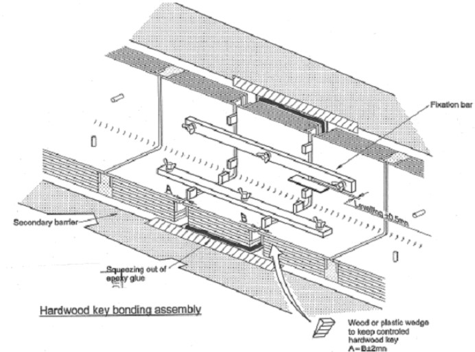
The assembly is centered (+/- 2 mm) and adjusted. After adjustment of the steel corner in line with the adjacent steel corner (leveling +/- 0,5 mm) the squeeze out of glue along side the edges has to be checked. (See Figure 3.)
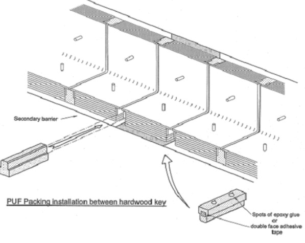
After curing of glue and dismantling of the positioning jigs, packing will be installed between keys. (See Figure 4 and 5.)
Bonding of Hardwood Key Assembly Between Trihedron and Corner Panel
The hardwood key assemblies is to be adjusted at the correct width according to on board measurements. (See Figure 6.)
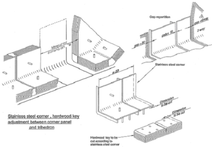
The assembly is bonded on the secondary membrane following same principle described above.
Bonding Procedure Qualification Test for Hardwood Key
A bonding procedure qualification test (BPQT) for hardwood key has to be carried out.
The bonding qualification test procedure has to define the following:
- Specification of the glue given by the manufacturer:
- color;
- density;
- mixing ration;
- pot life;
- open time;
- curing time.
- The specification of the glue dispenser.
- The specification of the parameter, which fix the type and size of epoxy glue according to the actual gap between the hardwood key and the secondary barrier.
Bonding of Top Bridge Pads
General
Top bridge pads (TBP) are installed between prefabricated panel top pads and also steel corner/hardwood key after fitting of S-triplex secondary barrier.
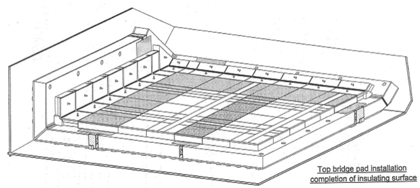
They complete the primary insulation and provide a flat surface for the erection of the corrugated membrane. (See Figure 7.)
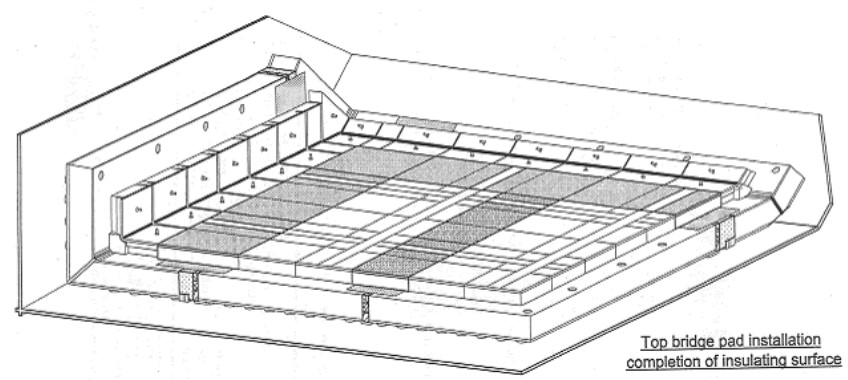
The top bridge pads along side the tank edges have to be adjusted to take in account the tolerance of the cargo holds.
TBP, which include stainless steel anchoring strip, will be installed in line with the anchoring strip of adjacent panels.
Bonding of Top Bridge Pads Between Flat Panels
Once the S-triplex strip bonding has been check, TBP bonding can start. Before TBP installation, a template will be used to verify that once bonded it will be within the erection tolerances. (See Figure 8.)
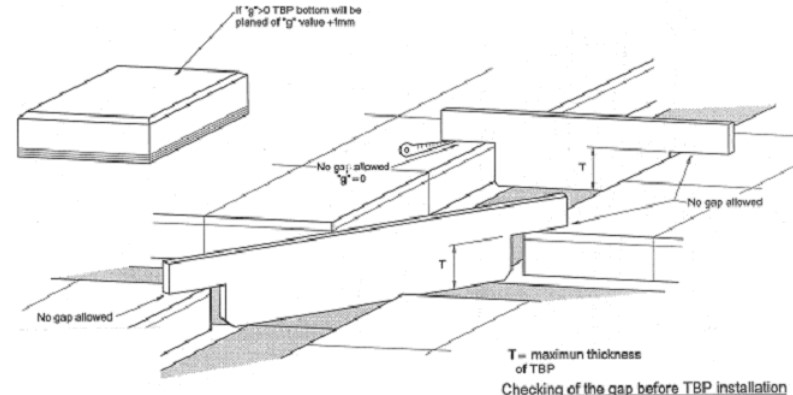
The epoxy glue is deposited by an automatic machine or manually by means of a spatula (usually by machine).
Thixotropic epoxy glue of different color will be used to avoid confusion.
The quantity of glue to be applied will be defined by test according to the required bonding criteria. (See Figure 9.)
To perform this test, the minimum thickness of TBP, which will be installed on board will be used with the maximum thickness of primary pads of panels.
The TBP will be centered to balance the gap on each side. Gap is to be below 4 mm. If the gap is above 4 mm, some insulating material (rock-wool) is to be inserted.
«As a general rule: any gap above 4 mm should be insulated to keep the a high efficiency of the insulating system.»
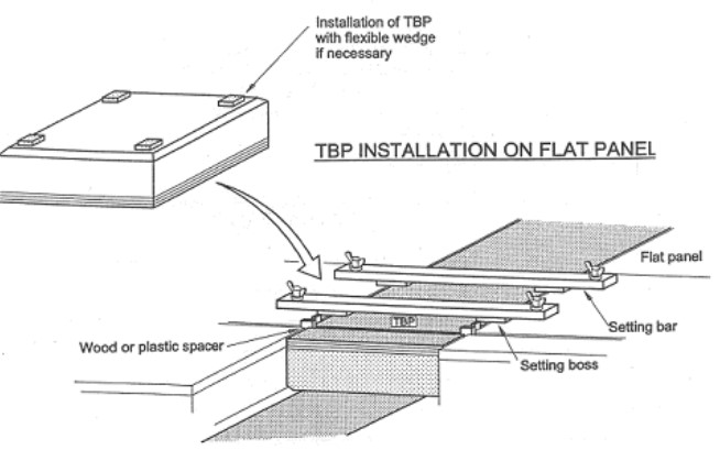
To keep the TBP at the level of panels during the curing of the glue, setting bars will be installed. Flatness tolerance with adjacent panels is +/- 0,5 mm. (See Figure 10.)
Bonding of Top Bridge Pad Alongside Corner Panel
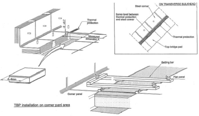
Alongside corner panels the TBP have to be cut according to the actual space on board minus 4 mm. The erection is basically the same as described above for the flat panels.
Alongside the chafer edges on transverse bulkheads, a wedge of 0,7 mm will be used on corner side under setting bars to make sure that the pad plus the thermal protection will be at the stainless steel corner level. (See Figure 11.)
Bonding Procedure Qualification Test
A bonding procedure qualification test (BPQT) for TBP has to be carried out.
The BPQT has to define:
- The specification of glue given by the manufacturer:
- color;
- density;
- mixing ratio;
- pot life;
- open time;
- curing time.
- The specification of the dispenser.
- The specification of the parameter, which fix the type and quantity of epoxy glue according the actual gap between the top bridge pad and the secondary barrier.
Insulation Completion – Protection and Final Check
Fitting of Thermal Protection Strips
Anchoring strips riveted on the flat panels have two functions:
- To be used for anchoring the membrane by tack welding.
- To be used as thermal protection for the overlap welding of two membrane sheets.
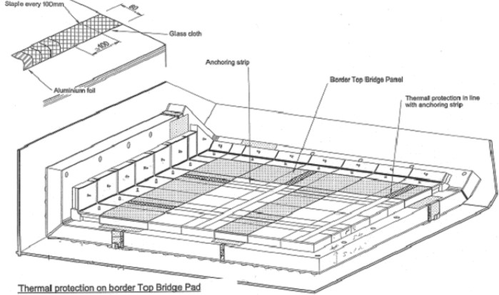
Because of the rigidity of the corrugations, it is not needed to anchor the membrane on border TBP alongside the corner panels so only protection is installed on these TBP.
Read also: Key Characteristics of Membrane Tanks Systems
The thermal protection 80 mm wide made by layers of fiber glass clothes sewn on aluminum foil will be stapled on the border TBP in line with the adjacent anchor strips. (See Figure 12.)
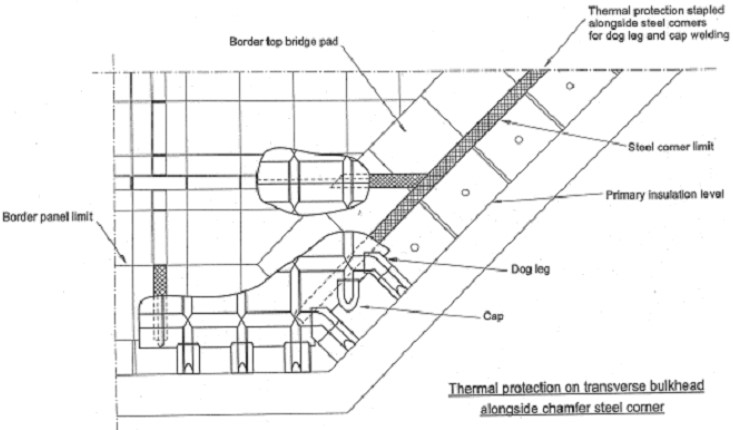
On transverse bulkheads, alongside chamfer steel corners, a thermal protection strip will be stapled for the welding of the dog legs and caps. (See Figure 13.)
Final Inspection of the Insulation
For membrane insulation the insulating surface must be clean:
- no dust;
- no trace of adhesive tape;
- grease;
- no protrusion of rivet;
- insert nuts;
- staple in the thermal protection;
- no plywood chip.
Also any gap between panels and TBP above 4 mm have to be filled with glass wool.
Read also: Best Practices for Gas Tank Installation and Cargo Tank Insulation
Previous describe tolerances will be globally checked again, unevenness and gap between TBP, panel and steel corner.
After completion and during installation, precautions will be taken to avoid to damage or dirty the insulation and secondary barrier. Protection on the bottom and lower chamfer is to be fitted.

