The article contains info about practical support arrangement of a cargo tank for Tank Type-A Liquefied Petroleum Gas carriers.
Purpose of the Study
- To provide information regarding optimised and practical design application to the support arrangement of a cargo tank.
- Consequences of reduction in number of supports with respect to scantlings of the cargo tank and double bottom structures
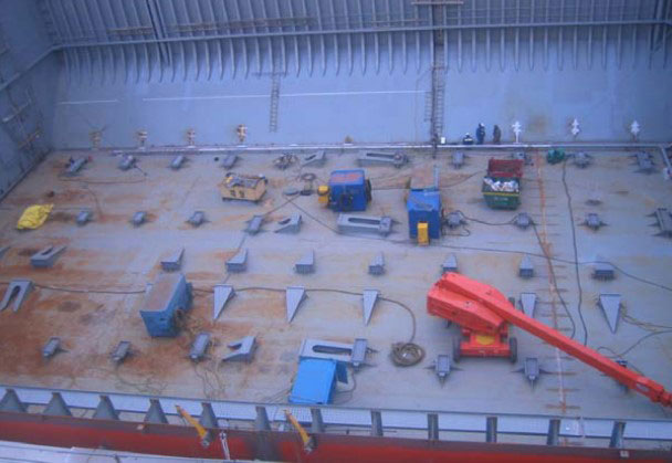
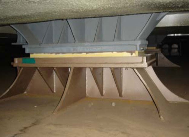
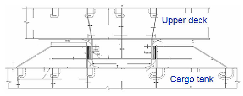
Tank support arrangement & type of supports
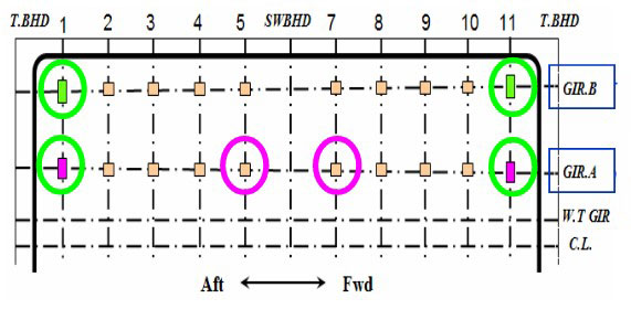
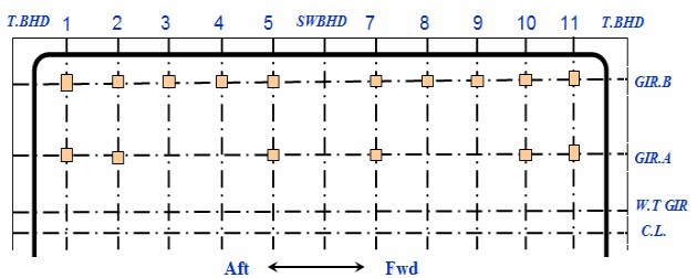
Support Arrn’t at Mid C/T I/B
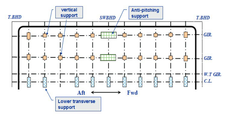
- Vertical supports arranged at each web frames.
- Transverse supports arranged at CL of each web frames.
- Anti-pitching supports located at mid length of a cargo tank.
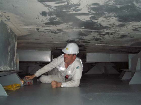
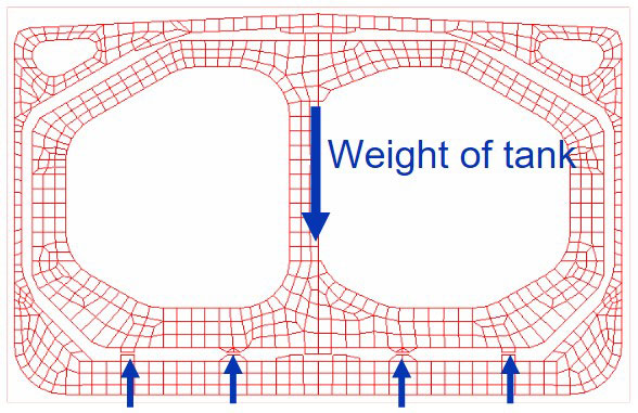
Vertical Support
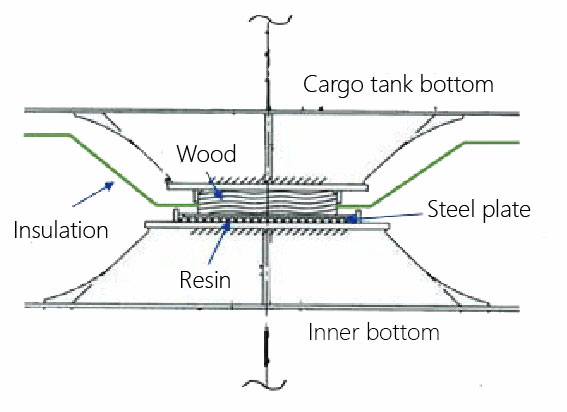
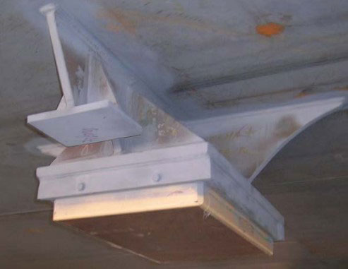
- To be designed to prevent hull structures from excessive stress concentration.
- Vertical supports are subject to horizontal forces due to friction.
- Strength of wood and resin to be checked in view of compressive strength.
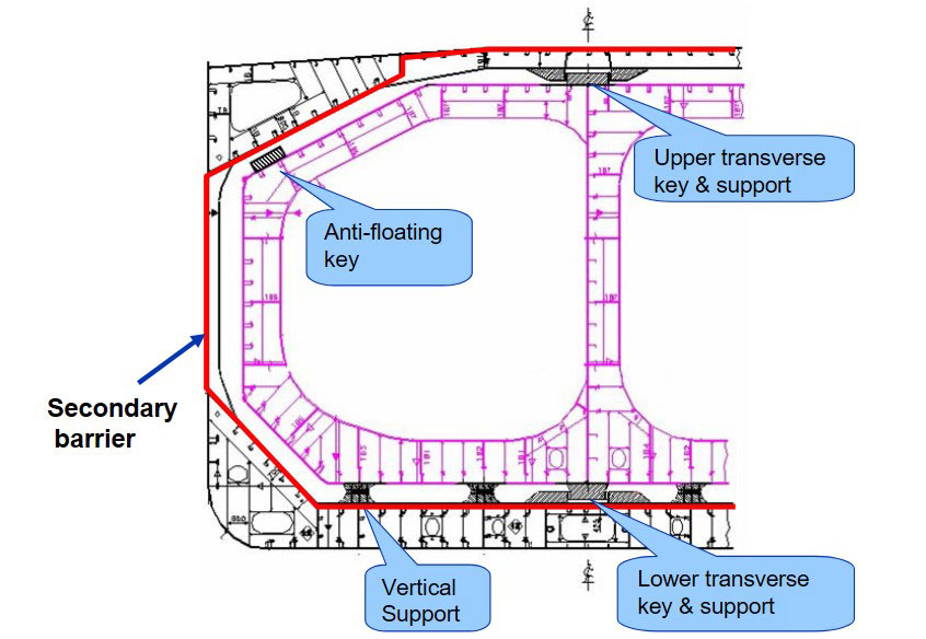
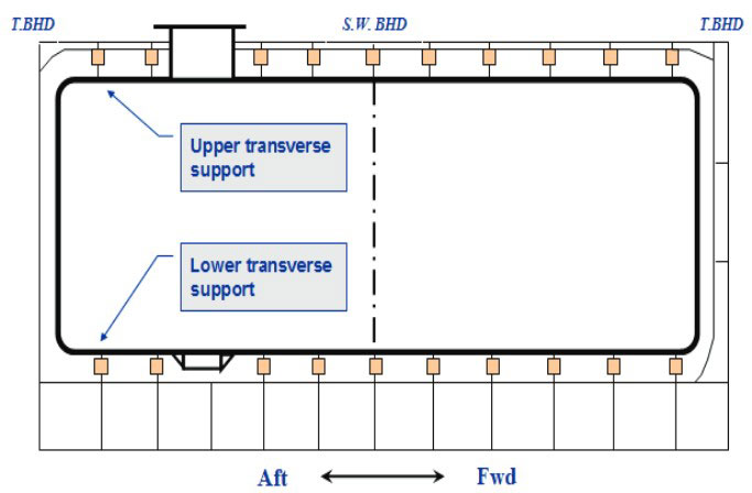
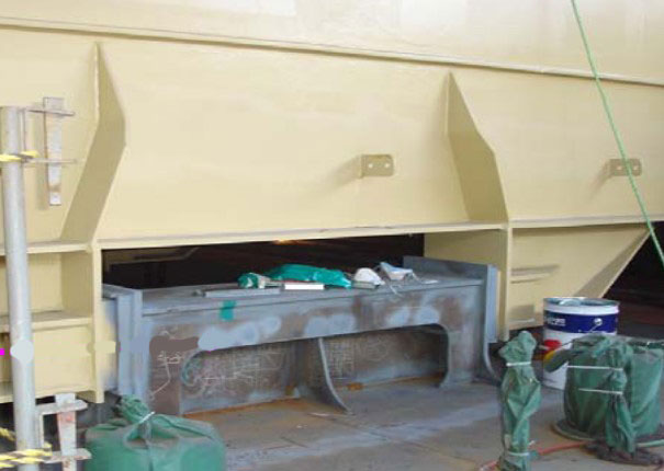
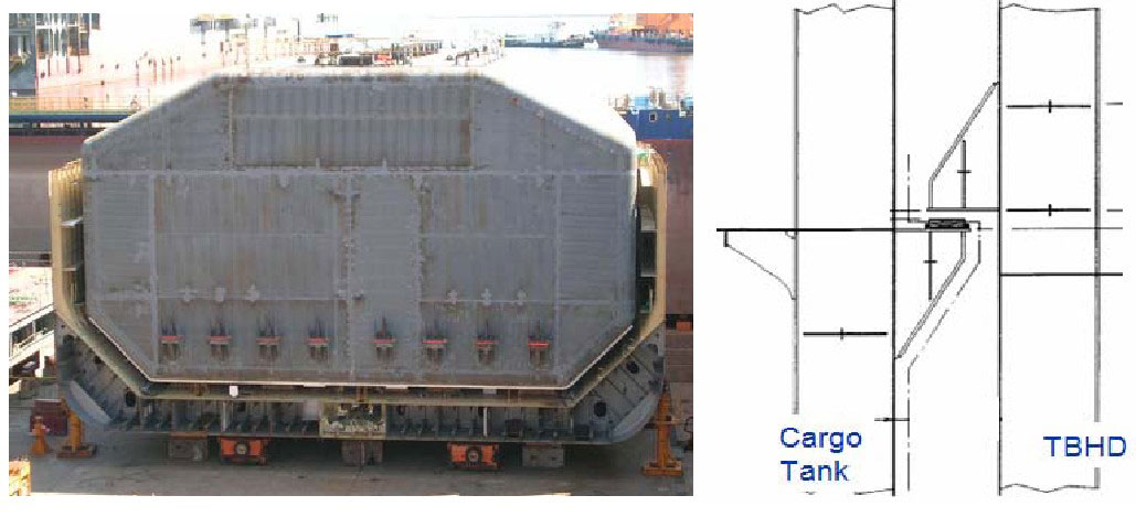
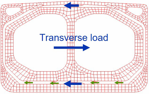
Transverse Key & Support
To prevent possible damage due to thermal expansion and contraction:
The collision forces acting on the cargo tank should correspond to acceleration:
- 0,5 g in the forward direction,
- 0,25 g in the aft direction.
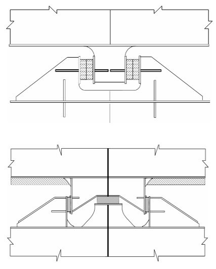
Anti-floating Key & Support
- To be suitable to withstand an upward force caused by an empty cargo tank in a hold space due to flooding.
- Normally, arranged at upper slope area of a cargo tank.
- Some design is arranged at end bulkheads of a cargo tank.
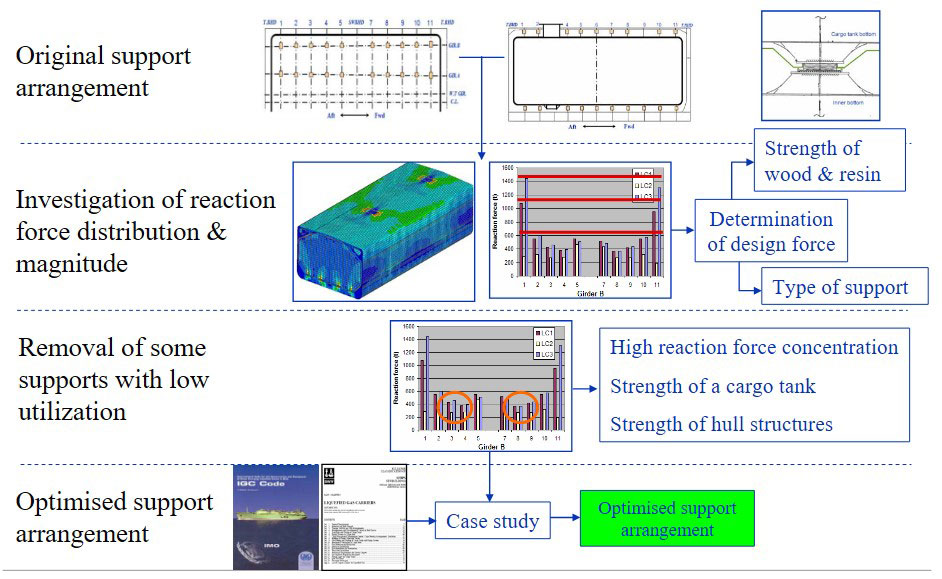
Investigation of existing designs of Tank Type A LPG ships

Existing Tank Type A Designs
- Principal particulars.
- Design parameters.
| Ship | A | B | C | D |
|---|---|---|---|---|
| Cargo volume, m3 | 82 000 | 60 000 | 38 000 | 23 000 |
| LBP, m | 212 | 195 | 172 | 155 |
| Breadth, m | 36,6 | 32,2 | 29,2 | 26,2 |
| Depth, m | 22 | 20,8 | 18,2 | 15,3 |
| Scantling draught, m | 12,55 | 12,1 | 10,4 | 8,4 |
| Block coeff., Cb | 0,78 | 0,767 | 0,779 | 0,734 |
| Number of cargo tank | 4 | 4 | 3 | 3 |
| Tank length, m | 37,92 | 32,95 | 42,3 | 36,65 |
| Design density, t/m3 | 0,61 | 0,69 | 0,70 | 0,68 |
| Web frame spacing, m | 3,36 | 3,2 | 3,2 | 2,4 |
- Number of keys/supports.
| Ship | A | B | C | D | |
|---|---|---|---|---|---|
| Vertical supports (P & SB) | Tank | 148 | 144 | 112 | 154 |
| Hull | 148 | 144 | 112 | 154 | |
| Transverse keys & supports (CL) | Tank | 82 | 82 | 64 | 82 |
| Hull | 82 | 82 | 64 | 82 | |
| Anti-pitching keys & supports | Tank | 16 | 16 | 12 | 12 |
| Hull | 16 | 16 | 12 | 12 | |
| Anti-floating Support | Tank | 82 | 82 | 42 | – |
| Hull | – | – | 42 | 82 | |
| Total | 574 | 566 | 460 | 578 |
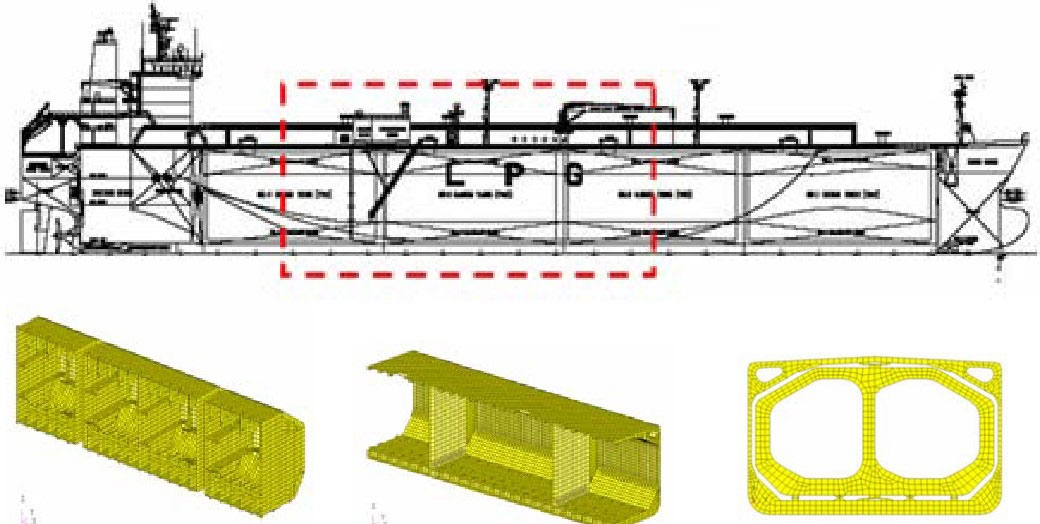
- Model extent is no. 3 plus half of tank no. 2 and 4 (1/2 + 1 + 1/2).
- The supports are interconnected by beam element for material of wood between cargo tank and hull structure.
- All structural elements are modelled based on the net scantlings.
Design Load Cases
| Support Type | Load case | Loading Condition | Tank load | Sea pressure | |||
|---|---|---|---|---|---|---|---|
| static | Sta. + dyn | static | Sta. + dyn | ||||
| Vertical support | LC1 | Full load condition Draught: Tsca. | X (10-8 level) | X |  | ||
| LC2 | Full load condition Draught: Tsca. | X | X (10-8 level) |  | |||
| LC3 | Full load condition Draught: Tact. | X (10-8 level) | X |  | |||
| Transverse support | LC4 | Heeled condition of 30 deg. | X (10-8 level) | X |  | ||
- Design load cases based on actual loading manual.
- The loads are calculated for a 20 years return period in the North Atlantic.
- Double bottom structures must be considered for:
- maximum net internal loads (downwards), LC1 & LC3;
- maximum net external loads (upwards), LC2.
Verification of Applied Loads
| Vertical support | |||
|---|---|---|---|
| Load case | LC1 | LC2 | LC3 |
| Tank weight, ton | 1 189 | 1 189 | 1 189 |
| Cargo weight, ton | 19 920 | 13 337 | 19 920 |
| Total weight, ton | 21 109 | 14 526 | 21 109 |
| Sum of reaction force, ton | 21 110 | 14 530 | 21 108 |
| Transverse support | |
|---|---|
| Load case | LC4 |
| Volume of tank, m3 | 21 779 |
| Max. transverse acceleration, ay | 0,6605*g |
| Applied transverse load, ton | 8 762 |
| Sum of reaction force, ton | 8 761 |
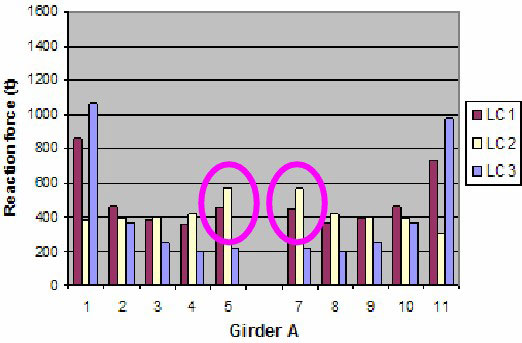
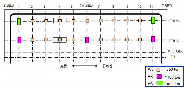
Ship A, 82 000 m3 LPG – Vertical Supports
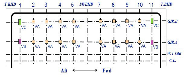
Reaction force distribution in supports
Max. reaction force & Design loads:
- Type VA: 596 ton => 650 ton.
- Type VB: 1 060 ton => 1 100 ton.
- Type VC: 1 444 ton => 1 500 ton.
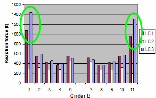
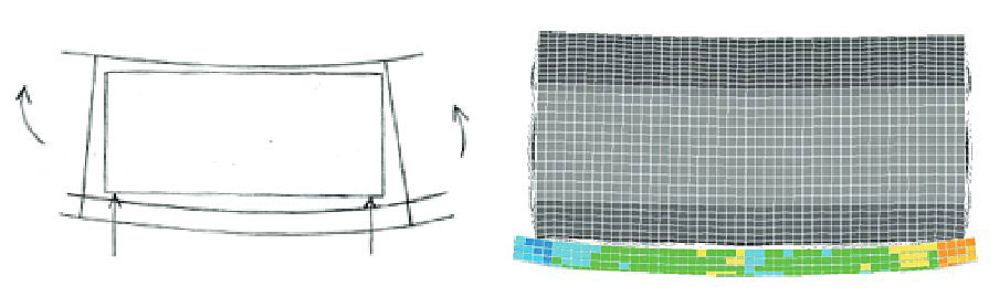
Effect of Hull Girder Bending – LC1 & LC3
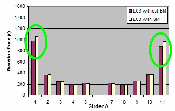
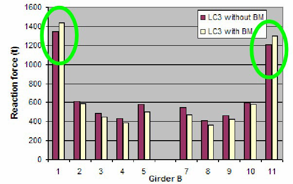
Sagging moment will increase support forces close to TBHD.
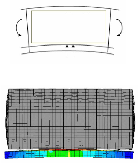
Effect of Hull Girder Bending – LC2

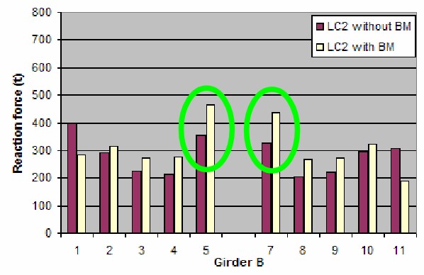
Hogging moment will increase support forces in way of mid supports.
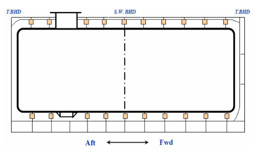
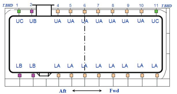
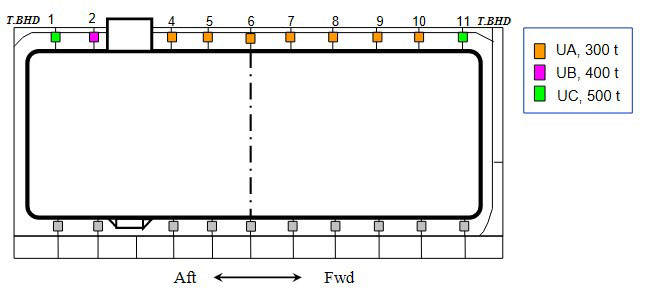
Transverse Supports
Transverse support arrangement.
Max. reaction force & Design loads.
Upper transverse support:
- Type UA: 261 ton => 300 ton.
- Type UB: 360 ton => 400 ton.
- Type UC: 478 ton => 500 ton.
Upper transverse support:
- Type LA: 469 ton => 500 ton.
- Type LB: 634 ton => 650 ton.
Type of support.
Reaction Force at Transverse Supports
Transverse support arrangement.
Distribution of reaction force at keys.
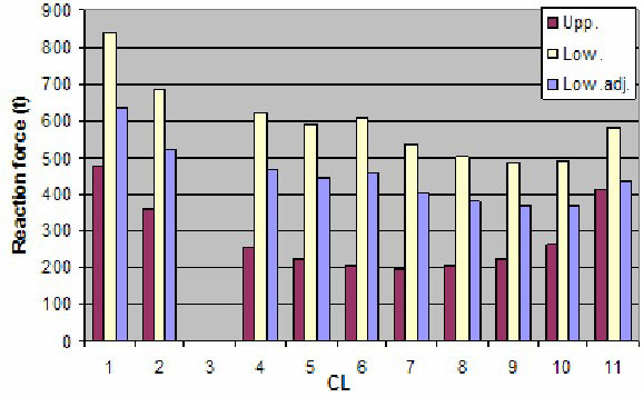
- For upper part, high force at keys close to end bulkheads and gas dome.
- For lower part, high force at keys close to end bulkhead and sump well.
- Reaction force at lower supports is higher than upper ones.
- Applied transverse load:
- upper part 32 %;
- lower part 68 %.
Case studies on support arrangements
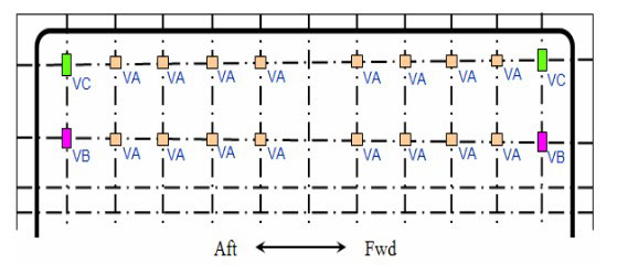
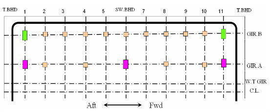
Vertical Support Arrangement – Case Study
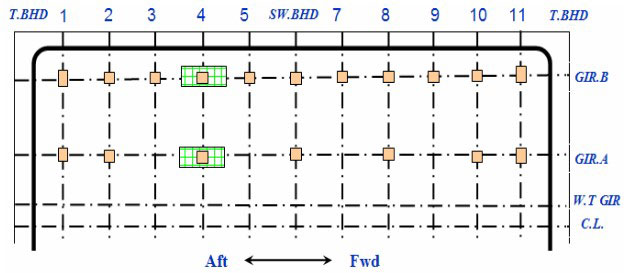
Support Arrangement – Case 2
Vertical supports is fitted at swash bulkhead location.
Some supports at GIR.A are removed at every second.
Anti-pitching support is relocated with combined type with vertical support.
Reaction Force Distribution – Case 2
Reaction force is mainly redistributed into mid supports, location 4, 6 and 8.
LC1 is critical to location 2 & 10 of GIR.A.

LC2 is critical to location 4, 6 & 8 of GIR.A.
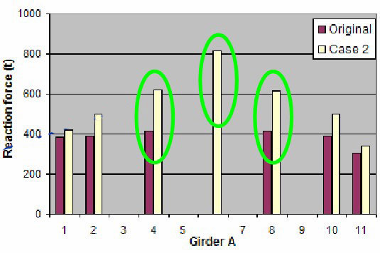
LC3 has little variation.

Shear strength capacity due to access opening.
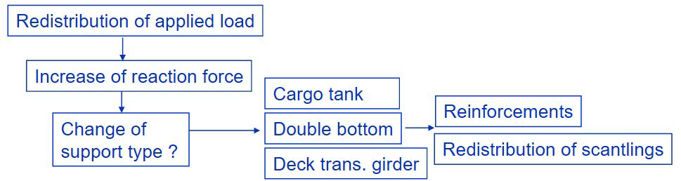
Consequences on a cargo tank and double bottom structures
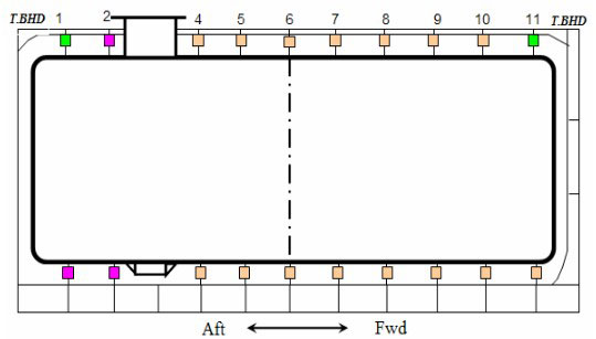
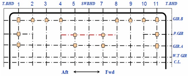
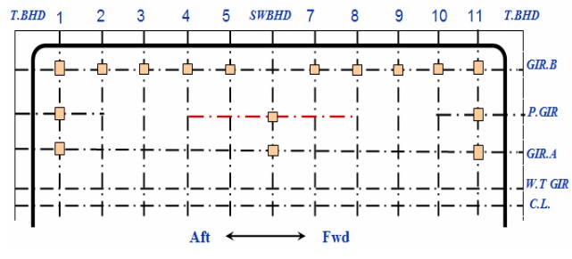
Transverse Support Arr’n – Case 1
Some of upper transverse keys are removed at every second.
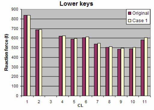
Lower transverse keys are kept.
Reaction Force Distribution – Case 1
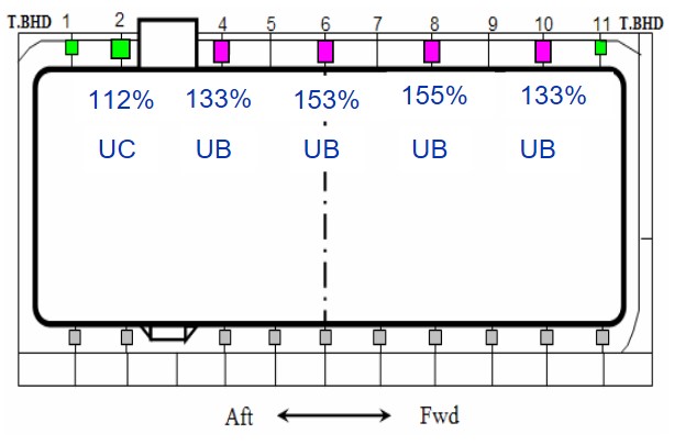
Reaction force at upper keys shows high increase, max. 55 % at location 8.
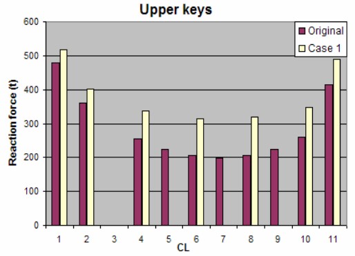
Type of support is changed.
Lower keys have little variation in reaction force.
Conclusion
Effect of hull girder bending in view of reaction force.

When some of the supports with low utilization are removed.