Welcome to the website where you can pass online the Seafarer Evaluation Training System (SETS) test on «EM7: Operate Electrical and Electronic Equipment». Practice like this will help you as a marine specialist improve your knowledge with the help of online studying and appraisal practice. SETS based on practical information and marine specialists experience.
SETS tests developed for evaluating seaman basic knowledge by company “Naval Education Services” is an evaluating online-tool, used for revealing any professional preparation needed in specific fields of knowledge, defined by STCW Section A-V/1-2.
SETS tests have proven themselves as good tools for the selection and recruitment process, as well as advancing the level of knowledge of the current officers and crew.
Current test contains SETS questions in area «EM7: Operate Electrical and Electronic Equipment». Those questions can be used for competence verification specialist capable of preventing accidental situations related with transporting safety, or also for self-examination.
«EM7: Operate Electrical and Electronic Equipment» subject includes theoretical and practical information about advanced training for work on any type of vessel. This test is designed to evaluate a mariner’s comprehensive ability to safely operate, maintain, and troubleshoot a vessel’s electrical and electronic systems. Candidates must demonstrate a firm theoretical understanding of electrical principles, including Ohm’s Law, power calculation and the functionality of major components like transformers and circuit breakers. A significant portion of the test assesses practical skills in using multimeters, insulation testers and other diagnostic tools to identify and rectify faults in circuit panels. The assessment includes scenarios on managing power distribution systems, ensuring a seamless transfer between the main generator and the emergency power supply. Test-takers will be evaluated on their knowledge of safety procedures, including lock-out/tag-out (LOTO) protocols and the correct response to electrical emergencies such as shocks or fires. Practical tasks require the calibration and operation of key electronic navigation and communication equipment, such as RADAR, ECDIS and GMDSS consoles. The exam covers the interpretation of electrical diagrams and schematics to trace circuits and understand the interconnection between different shipboard systems. Successful completion certifies the advanced competency needed to ensure the operational reliability and safety of all electrical and electronic equipment on any type of vessel.
On this site SETS on the subject «EM7: Operate Electrical and Electronic Equipment» contains 39 questions you need to answer with no possibility to go back to previous question. Therefore, we recommend carefully reading each question and making decision with no hurry. In case you have some difficulty answering, you have also possibility to request a hint.
Choose the regime, in which you want to pass SETS test:
Training
Exam
Start test
* Some questions may have more than 1 correct answer.
“SETS test” finished! Your result:
Correct answers:
⭐
Youve answered 5 questions
Get Premium to unlock the full version of this test, plus 1,000+ other practice exams.
Seafarers who prepare with Premium for just 20 minutes a day are 82% more likely to land their dream job.
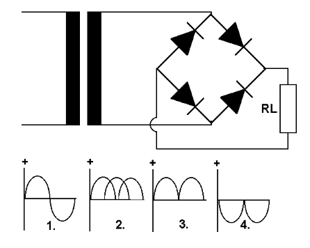
From the sample diagrams shown, choose the correct voltage waveform measured across the load.
1.
2.
3.
4.
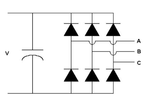
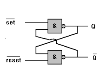
What is the function of the circuit shown here?
DC to AC voltage converter.
Three phase rectifier.
Three phase AC converter.
Three phase oscillator.
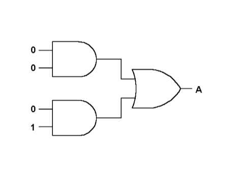
What will be the binary output at A?
1.
0.
1 1.
1 0.
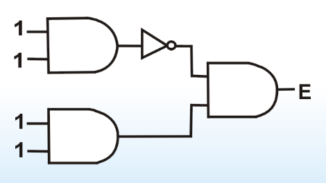
What will be the binary output at E?
1.
0.
1 0.
1 1.
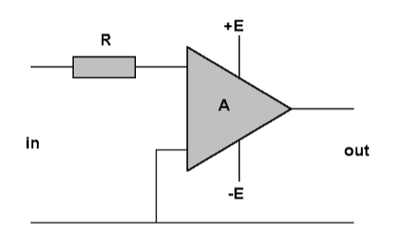
Indicate the correct characteristic of the amplifier "A".
An input impedance lower than 1 000 Ohm.
A voltage gain greater than 100 000.
An output impedance greater than 10 000 Ohm.
A frequency range less than 1 kHz.
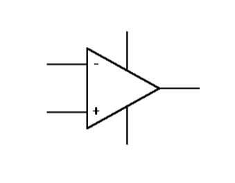
An ideal operational amplifier is characterised by:
Infinite input impedance.
Infinite output impedance.
Limited bandwidth.
Limited open loop voltage gain.
What does this symbol represent?
A differential trigger.
A binary register.
A binary flip-flop.
A digital amplifier.
What is a high-pass filter?
A circuit that will only pass a high voltage.
A circuit that blocks a high voltage.
A circuit that will limit resistance.
A circuit that will only pass high frequency signals.
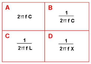
Which of these formulas is used to calculate capacitive reactance (Xc)?
A.
B.
C.
D.
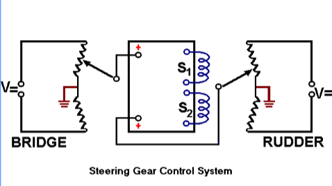
The second potentiometer of this electric command system is located in the steering gear. What moves this potentiometer?
The telemotor.
The rudder angle indicator.
The rudder position via the trunion connection.
The eccentric pushrod on the HELE-SHAW pump.
How is the set pressure (opening pressure) adjusted on the cylinder head safety valve of a diesel engine?
By adjusting the distance of the valve cone.
By adjusting the lift height of the spindle.
By fitting distance washers.
By adjusting the spring pressure.
What control equipment drawing is shown here?
An electric P-controller.
An electric differentiating amplifier.
An electric temperature measurement scanner.
An electric pressure transmitter system.
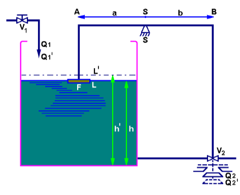
Here "S" is the support point in the middle of pivoting arm "AB". For a given increase in water level the valve is opened by the same distance, therefore the amplification is 1. What will happen if b = 2 × a?
The water will drop twice as fast in the tank.
The valve will open twice the distance of the increased level.
The amplification is increased by 50 %.
The process will not longer working.
A six-pole asynchronous motor is connected to a power supply with a frequency of 50 Hz. If the rotor bar frequency is 2,3 Hz, what will be the speed of the motor?
972 RPM.
954 RPM.
928 RPM.
912 RPM.
A star connected induction motor operates on 220 V with power factor 0,7 and efficiency of 82 %. Its output is 8 HP. What is the phase, current and voltage?
I phase is 12,8 Ampere, phase voltage is 220 Volt.
I phase is 27,3 Ampere, phase voltage is 127 Volt.
I phase is 15,8 Ampere, phase voltage is 220 Volt.
I phase is 22,7 Ampere, phase voltage is 127 Volt.
A 3-phase 60 cycle motor delivers 50 HP to a pump (shaft output). What is the torque if the RPM is 1 176 RPM?
223 pound-feet.
175 pound-feet.
275 pound-feet.
250 pound-feet.
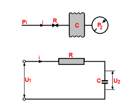
In these integrator circuits the air flow through the restrictor and the current through the resistance:
Remains constant.
Decreases with time.
Increases with time.
Is negative.
What is the difference in function between these electrical and the pneumatic integrators?
None.
The pneumatic integrator is slower.
The electric integrator is slower.
They work in opposite directions.
The size of any electrical conductor should be such that in practice, the voltage drop at full load will not exceed:
1 %.
2 %.
3 %.
5 %.
Two 3 phase 4 160 Volt, 60 Hz alternators are operated in parallel. The total load of the system is 1 050 kW with power factor 0,75 lagging. If alternator No 1 is carrying 700 kW at 80 % power factor lagging:
The Power Factor of alternator No 2 is lagging 0,7352.
The Power Factor of alternator No 2 is lagging 0,7064.
The Power Factor of alternator No 2 is lagging 0,6914.
The Power Factor of alternator No 2 is lagging 0,658.
Alternator (A) 100 kVA runs parallel with alternator (B) 125 kVA, both are 3 phase, 240 V, 60 Hz. The load of A is 60 kW, 90 % power factor and the load of B is 80 kW, 70 % power factor. What is the total load?
472,8 Amps.
458,8 Amps.
429,8 Amps.
416,8 Amps.
The pick up and the time settings of reverse power relays are adjustable. If the prime mover of the alternator is a steam turbine what is the trip level setting?
0,5-1 %.
2-3 %.
4-6 %.
6-7 %.
If the prime mover of an alternator is a diesel engine, what should the Reverse Power Relay's pick up setting be?
5-10 %.
10-15 %.
8-10 %.
5-12 %.
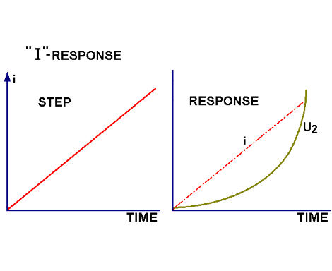
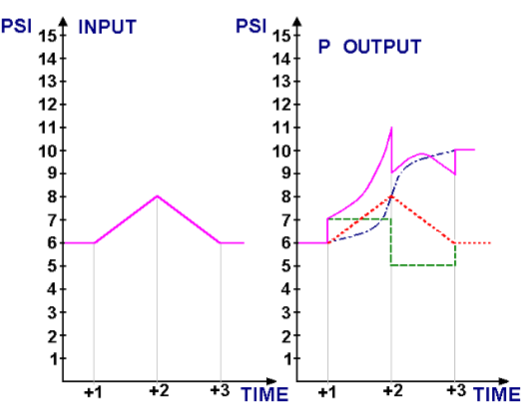
The characteristics shown here indicate a ramp input on the left together with the corresponding output on the right of:
a proportional controller.
a pure integrator.
a pure differentiator.
a proportional integrating controller.
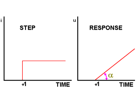
These graphs are, left, the step input and, right, the output response of a controller. What characteristics are shown?
The controller response output characteristics.
The integrator characteristics.
The PI characteristics.
The integrator differential characteristics.
For which type of controller are the input and output characteristics shown here?
A pressure indicating controller.
A proportional integrating controller.
A PI differentiating controller.
A pneumatic indicating controller.
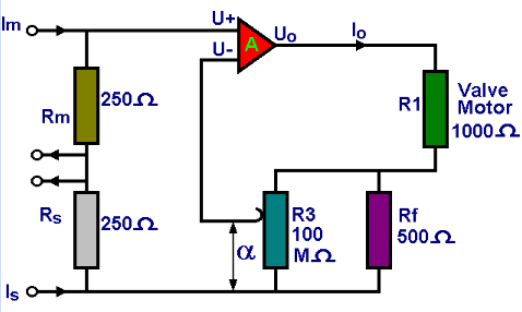
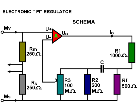
In this drawing, the triangle marked "A" represents:
An operational amplifier.
An ampere-differential transmitter.
An analog converter.
A current converter.
Which resistor determines the proportional band on this electronic proportional integrating controller?
Rf.
R1.
R2.
R3.
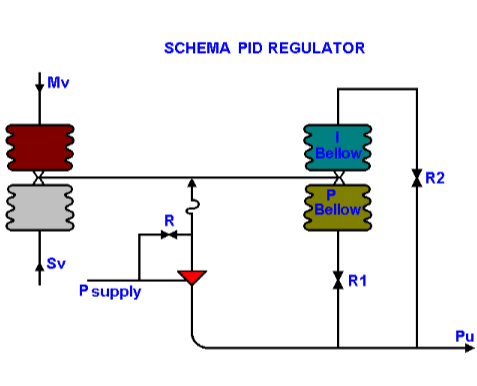
Fitting a restriction R1 in the supply to the proportional feedback of this PID controller ensures that for an initial small variation on the input, the initial response on the output will be:
Zero.
Very weak.
Proportional.
Strong.
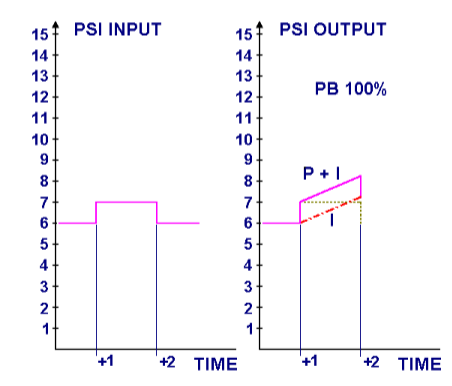
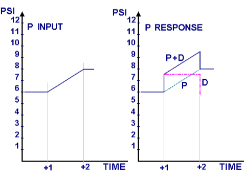
For which control instrument are these the input (left) and the output or response (right) characteristics?
A pressure differentiator.
A proportional differentiating controller.
A pressure controlling data register.
A pneumatic differentiating controller.
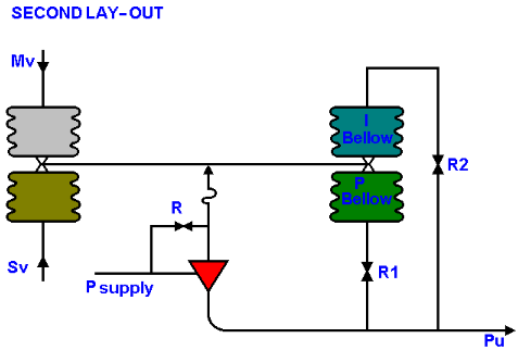
For this PID controller to act only as a P (proportional) controller, what should be the arrangement of restricting valves R1 and R2?
R1 fully open, R2 closed.
R1 fully open, R2 fully open.
R1 closed, R2 closed.
R1 closed, R2 fully open.
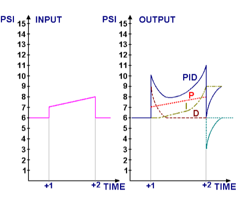
For which kind of controller are the input and output characteristics shown here?
A pressure indicating controller.
A proportional integrating-differentiating controller.
A proportional indicating differentiator.
A pneumatic differential summator.
In the output characteristics (right) of this controller, which response lines are clearly shown?
The output, variation and differentiation.
The proportional output, offset and integration.
The proportional, integration and differentiation.
The proportional, variation and integration.
How is the differentiating action of this PID controller obtained?
By C and R1.
By C and R2.
By C and R3.
By C and R4.
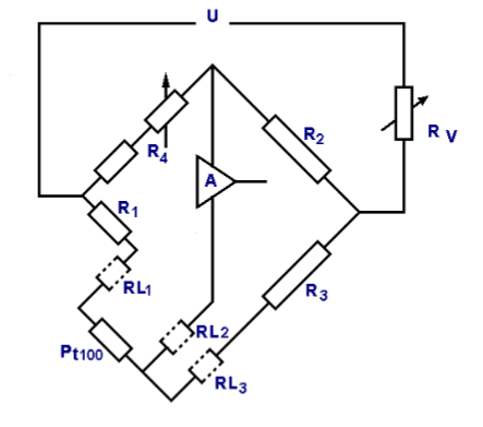
The three conductor system used by Wheatstone Bridge lay-outs is intended to provide:
Compensation for changing conductor resistance by changing temperature.
Zero setting at all times by variable resistances to be measured.
Balancing of the bridge by very high or very low temperatures.
Conversion of an electrical signal into a pneumatic signal.
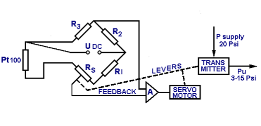
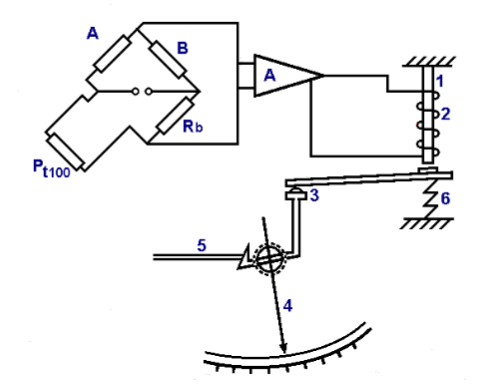
The function of this measuring system is to:
Convert a digital signal into a pressure.
Convert an electric temperature measurement into a pneumatic signal.
Convert Wheatstone Bridge readings into remote pressure readings.
Convert Field Effect Transistor readings into a temperature reading.
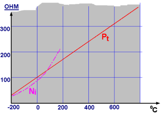
The resistance characteristic of Platinum is linear. The resistance characteristic of Nickel is non-linear. How can the characteristic of Nickel be made linear?
By using a three-wire system Wheatstone Bridge.
By fitting a compensation cable.
By fitting another resistance in parallel.
By fitting another resistance in series.
Item No 2 of this Wheatstone Bridge is:
The field wire fed by amplifier A.
The feed-back coil fed by amplifier A.
The field balance indicating field wire of amplifier output.
The thermal resistance fed by the output of amplifier A.
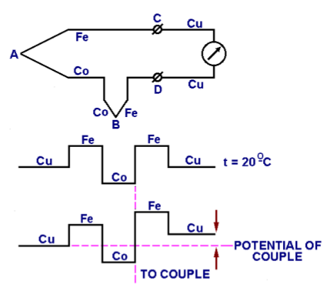
The potential of this thermocouple bridge is zero if all connections are kept at the same temperature. Why is the indication of the potentiometer zero?
Because of the second balancing couple B.
Because of the copper (Cu) calibration wiring connected to C and D.
Because A and B couples are opposed.
Because the connections in A and B and in C and D are opposed.
Did you find mistake? Highlight and press CTRL+Enter