Welcome to the website where you can pass online the Seafarer Evaluation Training System (SETS) test on «EM3: Operate, Monitor and Evaluate Engine Performance». Practice like this will help you as a marine specialist improve your knowledge with the help of online studying and appraisal practice. SETS based on practical information and marine specialists experience.
SETS tests developed for evaluating seaman basic knowledge by company “Naval Education Services” is an evaluating online-tool, used for revealing any professional preparation needed in specific fields of knowledge, defined by STCW Section A-V/1-2.
SETS tests have proven themselves as good tools for the selection and recruitment process, as well as advancing the level of knowledge of the current officers and crew.
Current test contains SETS questions in area «EM3: Operate, Monitor and Evaluate Engine Performance». Those questions can be used for competence verification specialist capable of preventing accidental situations related with transporting safety, or also for self-examination.
«EM3: Operate, Monitor and Evaluate Engine Performance» subject includes theoretical and practical information about advanced training for work on any type of vessel. This test is designed to rigorously assess your comprehensive understanding of marine propulsion systems and their operational parameters. It will test your ability to analyze and interpret engine performance data, including power output, fuel consumption and efficiency calculations. You can expect practical scenarios requiring the diagnosis of common engine malfunctions and the implementation of appropriate corrective procedures. A key focus area is evaluating your competence in monitoring engine systems through instrumentation and alarm management to ensure safe operation. The test assesses your knowledge of implementing proper safety and emergency protocols during all operational phases of the engine room. You will be required to demonstrate how to conduct performance evaluations to optimize fuel efficiency and plan necessary maintenance. Questions will cover the specific procedures for operating and monitoring machinery across various vessel types and environmental conditions. Successfully passing this assessment validates the essential competencies required for advanced engineering duties on modern merchant vessels.
On this site SETS on the subject «EM3: Operate, Monitor and Evaluate Engine Performance » contains 50 questions you need to answer with no possibility to go back to previous question. Therefore, we recommend carefully reading each question and making decision with no hurry. In case you have some difficulty answering, you have also possibility to request a hint.
Choose the regime, in which you want to pass SETS test:
Training
Exam
Start test
* Some questions may have more than 1 correct answer.
“SETS test” finished! Your result:
Correct answers:
⭐
Youve answered 5 questions
Get Premium to unlock the full version of this test, plus 1,000+ other practice exams.
Seafarers who prepare with Premium for just 20 minutes a day are 82% more likely to land their dream job.
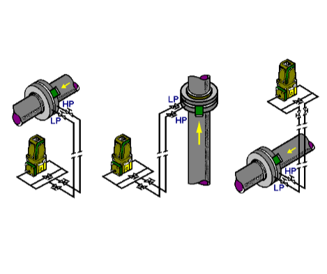
To prevent clean liquid mixing with the in-coming dirty liquid.
To accelerate the liquid to the same speed as the bowl.
To reduce the bowl speed to adapt to the type of liquid.
To keep the liquid separated.
The use of a steam trap has a beneficial influence on the thermal balance of the heat exchanger fitted before that trap. This is because:
It will allow the steam to expand to atmospheric pressure.
All heat is used under corresponding saturated pressure.
All heat will be extracted from the steam before turning to water.
It will allow the steam to expand below atmosphere to vacuum.
A ship's propeller is 4 882 mm in diameter with pitch of 4 226 mm. The engine RPM is 122. Assuming no slip what is the ship's speed?
19,29 knots.
18,44 knots.
16,7 knots.
15,22 knots.
A ship's main engine runs at 114 RPM. The slip that day was 7,4 %. If the ship's speed that day was 13,82 knots, what is the pitch of the propeller?
4 426 mm.
4 182 mm.
4 040 mm.
3 938 mm.
A vessel has a propeller with 3 828 mm pitch and makes 109 RPM. If the sea speed is 12,8 knots, what is the slip?
8,3 %.
3,8 %.
5,3 %.
3,5 %.
A diesel engine cylinder diameter is 700 mm, its stroke is 1 200 mm, its IMP is 8,9 bar and its revolutions 120 RPM. What is the POWER developed per cylinder?
1 095 IHP.
2 052 BHP.
1 633 shaft horsepower.
2 344 metric HP.
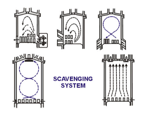
How is it ensured that the flow of the scavenge air is directed symmetrically through the cylinder?
By the uniflow system.
By the reverse system.
By the turbocharger.
By the scavenge port shape.
What factors influence the vacuum (vacuum %) inside the shell of a fresh water generator?
The temperature of the fresh water heating the evaporator.
The temperature of the sea water cooling the condenser.
The pressure of the ejector water on the vacuum ejector.
All of these.
As we can use only the linear part of the characteristic, this shows that the flapper can only travel 0,01 mm, therefore DELTA psi obtained can only be less than 1 psi. Can we use the flapper nozzle system?
No, the nozzle/flapper assembly needs modification.
No , the flapper system will gives erratic readings.
Yes, but the valves need a servo booster.
Yes, but the readings obtained between DELTA psi need to be amplified.
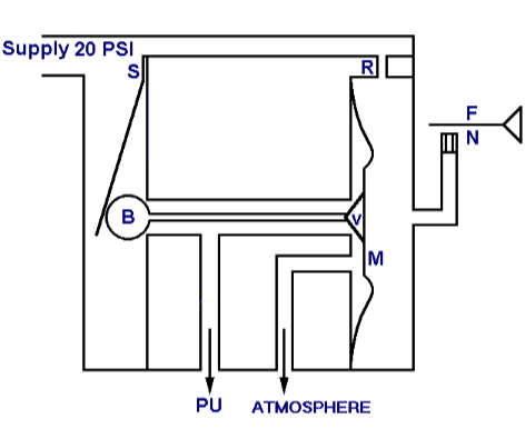
On which part of the Pneumatic Amplifier is the nozzle back pressure of the nozzle/flapper (NBP) acting?
On spring S.
On ball valve B.
On valve V.
On membrane M.
What is the function of ball valve B in relation to the outlet pressure Pu of this pneumatic amplifier?
To push the membrane back in place after each movement.
Opening port of 20 psi supply air access.
To push the atmospheric vent close, increase Pu.
To counteract the pressure on the membrane M, decrease Pu.
What is the function of valve V in relation to the outlet pressure Pu of this pneumatic amplifier?
To allow stabilising feedback pressure on the membrane.
To allow venting of pressure Pu to the atmosphere.
To transmit the pressure Pu to the membrane.
To push spring S open via the ball B.
These characteristics show Pu in relation to flapper distance and NBP of a pneumatic nozzle flapper and transmitter; thus with the smallest distance movements it fluctuates sharply. What is the result and the remedy?
Unsteady operation. Springs are to be fitted on all moving parts.
Tendency to close. Fit by pass nozzle to amplifier.
Tendency to open. Fit elongated flappers in output.
Unsteady operation. Bellows are to be fitted in pneumatic lines.
This is an actual lay-out drawing of a pneumatic amplifier block. Where is the 20 psi supply air admitted?
At air passage item 12.
At air passage item 13.
At air passage item 14.
At air passage item 15.
Via which air passage is the nozzle back pressure from the nozzle/flapper admitted for this pneumatic amplifier?
Air passage 12.
Air passage 13.
Air passage 14.
Air passage 15.
What is item No 3 shown of this pneumatic amplifier?
Retaining plates for the ball valve.
Blade (feather) springs to load the ball and the vent valve.
Nozzle flappers.
Ball valve securing blades.
How can the output pressure Pu of this pneumatic amplifier be initially adjusted?
By screw item 4.
By screw item 11.
By screw item 1.
By screw item 10.
What is part No 4 shown in this drawing of a pneumatic amplifier?
The air supply compartment.
The exhaust or vent compartment.
The output air compartment.
The nozzle back pressure supply compartment.
What is the amplification factor (K) of a pneumatic amplifier?
K = 4.
K = 12.
K = 16.
K = 20.
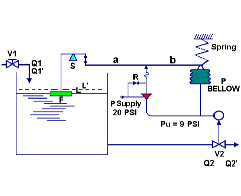
If the length of "a" is equal to the length of "b" what will be the proportional band "PB" of this pneumatic controller?
0 %.
25 %.
50 %.
100 %.
If Q1 is the filling volume of the tank and Q2 the outflow volume of the tank and the level L is constant by controller output pressure Pu = 9 psi, the valve V2 will be open for:
100 %.
75 %.
50 %.
25 %.
If the input flow Q1 increases to Q1' and level L increases to L' what will initially happen?
The amplifier will increase its air output pressurising bellow P.
The output pressure Pu will increase proportionally to L'.
The proportional band PB will change.
The amplification factor K will change.
What do you call the pneumatic mode of operating of the pneumatic controlled valve V2?
Positive activation.
Negative activation.
Air to Open.
Air to Close.
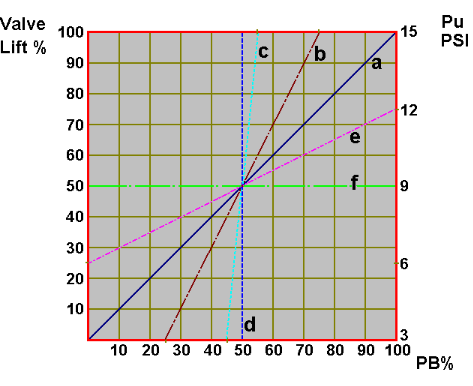
This characteristic shows the output pressure of a controller effecting valve lift. If PB = 100 % is the graph shown in "a". What is the graph of PB = 50 %?
Graph b.
Graph a.
Graph d.
Graph f.
This characteristic shows output pressure of a controller effecting valve lift. If PB = 100 % is the graph shown in "a". What is the amplification factor and the proportional band represented by graph "f"?
Amplification 50 %, Proportional Band 100 %.
Amplification 0, Proportional Band infinitive.
Amplification infinitive, Proportional band 0.
Proportional band 50 %, amplification 100 %.
Graph "d" of this characteristic showing output pressure Pu of a controller effecting valve lift, represents ZERO proportional band over INFINITIVE amplification. How does the system works?
It does not regulate the level at all.
It works with intolerable offsets.
It works with maximum range offsets.
It works FULL OPEN/FULL CLOSE, unsteady, offset NIL.
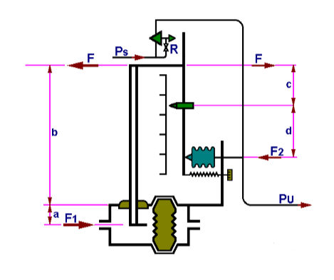
If the pressures in the MV and the SV bellows are equal, what will be the output pressure Pu of this pneumatic P-controller?
3 psi.
6 psi.
9 psi.
12 psi.
If the measured value bellow is connected to the output of the jacket CW temperature transmitter and the Pu of the controller is 9 psi, and we reduce the temperature setting from 75 to 72 degree C what happens to the Pu?
It will increase to 20 psi.
It will decrease below 9 psi.
It will increase above 9 psi.
It will decrease to 0 psi.
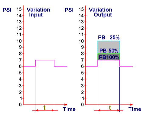
Suppose the variation of INPUT is 1 psi down instead of 1 psi up on this pneumatic P-Controller. If the proportional band PB is 25 % what will be the output pressure?
3 psi.
2 psi.
6 psi.
0 psi.
Suppose the INPUT of the pneumatic controller is 4 psi and the PB is 25 %. If variation on the input is 1 psi down, what is the variation on the output expressed in psi?
4 psi.
2 psi.
1 psi.
6 psi.
What would be the variation of output on this pneumatic controller if Proportional B and PB = infinity, by varying the input as shown here?
1 psi.
Infinity, full open, full close control system.
Between 3 and 15 psi.
No response, nil.
Suppose the Proportional Band of this pneumatic controller is increased to 500 % and the input variation remains the same. What would be the output variation?
1 psi.
5 psi.
0,2 psi.
0,5 psi.
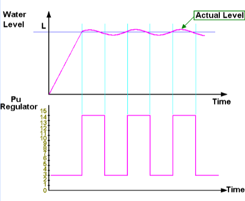
This characteristic shows output pressure of a pneumatic controller controlling water level. The level is fluctuating. What is wrong with the setting of the controller?
The span is too narrow.
The range is too large.
The proportional band is too small.
The amplification is too small.
Something is wrong with the controller setting of this water level control system. Suppose the Proportional Band is 12,5 %, to what value would you reset it?
20 %.
50 %.
100 %.
500 %.
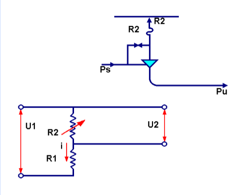
In this electrical amplifier drawing, what takes the place of the flapper/nozzle unit used by the pneumatic control unit with amplifier?
R2.
R1.
U1.
U2.
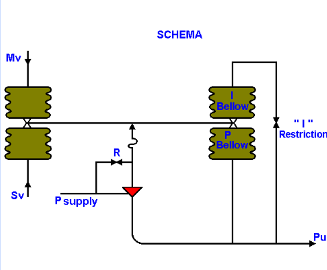
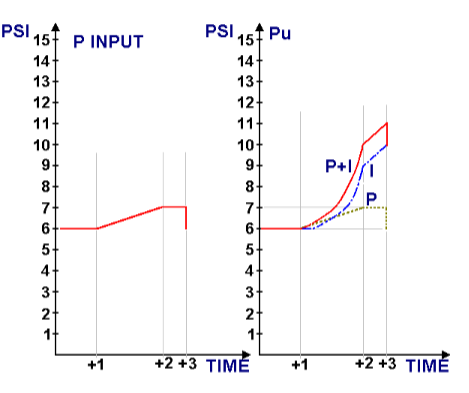
This drawing shows which kind of pneumatic controller?
A proportional controller.
A proportional integrating controller.
A proportional differentiating controller.
A proportional integrating-differential controller.
Since the output of the pressure transmitter is not linear with the flow in the pipe as measured over the measuring flange the output signal should be sent to a:
Balancing valve.
Equaliser.
Root extractor.
Summator.
From this drawing of a pneumatic pressure transmitter, what is the Proportional Band setting?
Proportional Band = 100 %, amplification K = 1.
Proportional Band less than 100 %, amplification K more than 1.
Proportional Band more than 100 %, amplification K less than 1.
Proportional Band 0 %, amplification infinitive.
For which type of controller are these the input (left) and the response (right) characteristics?
A pneumatic inverter.
A pneumatic integrator.
A pressure integrating controller.
A proportional integrating controller.
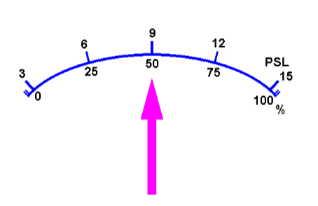
The manometer with scale indication shown here is fitted in the ............... line of a controller or valve positioner which supplies a pneumatic valve motor with "Pressure to ..... function".
Supply, "Close".
Input, "Open".
Output, "Open".
Input, "Close".
What measure of power developed inside a cylinder is obtained by using the formula PMI x cylinder section surface (cm2) x stroke (metre) : 75?
Brake horsepower.
Metric Horsepower.
Effective horsepower.
Indicated horsepower.
A ship makes an observed speed of 17 knots. The engine speed is 17,5 knots. What is the propeller slip?
28,5 %.
285 %.
,0285 %.
2,85 %.
An engine develops 2 500 IHP and the BHP is 2 000. What is the mechanical efficiency?
12,5 or 1250 %.
1,25 or 125 %.
0,8 or 80 %.
0,08 or 8 %.
Thermal efficiency refers to heat engines and is the ratio of:
Input to the output on the power take off.
Output on the shaft/flywheel to internally produced power.
Horsepower to BTU input of fuel.
Output to BTU converted in energy.
Which of the following is a record of the pressure existing in the cylinder at various positions of the piston throughout the engine cycle?
A Timing diagram.
An Indicator diagram.
A Temperature diagram.
A Cycle diagram.
The basic type of reversing air starting system that can be used only on two-stroke, ported, direct coupled, propulsion Diesel engines is the:
Rotating camshaft.
Reversing latch.
Sliding camshaft.
Distributor type.
To find the indicated power developed in the cylinder the indicator card is used to determine the:
Compression pressure.
Firing pressure.
Mean effective pressure.
Mean height of the diagram.
What method is employed in the design of waste heat boilers to obtain maximum heat transfer while maintaining low overall weight?
Steel fins are installed on the generating tubes to increase the effective surface area.
An unfired exhaust gas preheater is added to increase the heat transfer rate.
An external superheated unit is located above the boiler to the gas passages.
Feedwater is preheated in a separately fired economizer.
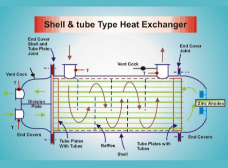
The flow through this heat exchanger is determined by the "Reynolds number". Depending on certain factors, this allows the system designer to select either:
Streamline flow or contra flow.
Turbulent flow or laminar flow.
Parallel flow or turbulent flow.
Parallel flow or contra flow.
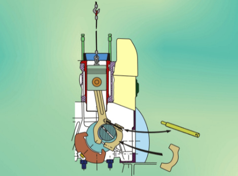
Why is this connecting rod eye split obliquely?
To decrease the bottom end bolt shock loading.
To avoid setting up unecessary stress in the rod eye.
To allow the piston/connecting rod to pass through the liner.
To allow access to both of the bolts and bearing from one side of the engine.
Did you find mistake? Highlight and press CTRL+Enter