Explore the implications of UltraHD technology on satellite and terrestrial distribution in this comprehensive article. Learn about the H.265 codec, bandwidth and transmission requirements, and the challenges associated with deploying UltraHD video.
This article assesses evolving Ultra High Definition video in general (known as UltraHD) and Ultra High Definition Television (UHDTV) services in particular; we refer to both as “UltraHD.” UltraHD affords what has been called an immersive viewing experience. Article looks at the opportunities for satellite operators in providing distribution services, as well as challenges and issues. Some of the largest satellite operators get 75 % of their revenues from video distribution, Direct to Home (DTH) in particular; hence, the topic can be important.
Satellite operators hope that the commercial service prospects for UltraHD are better than those that revolved around 3DTV. Three issues held back the 3DTV market, which are not applicable to, or impact, UltraHD. First, the distribution of 3DTV required only a relatively modest increment in additional bandwidth (around 30 %), except for the high-end multiangle applications (which did not even take off the ground), thus putting an upper bound on the net bandwidth (transponder) growth requirements; on the contrary, UltraHD intrinsically requires significant bandwidth augmentation in the transport network (satellite-based or terrestrial) to be delivered, thus offering, in principle, more business potential for the operators. However, this could also act as a retardant to the deployment of the UltraHD technology because of the more onerous set of resources needed and (possibly) the intrinsic cost involved. Second, the 3DTV required not only a new screen but also active or passive glasses to be worn by all content watchers; the latter issue does not impact UltraHD, although the former does. Third, the production of 3DTV video material can be difficult, even when the stereoscopic cameras are available, especially for live programs such as sporting events; by contrast, the production of UltraHD video material is technically simpler.
On a passing note, we remain convinced that 3DTV-like services may have market potential either on autostereoscopic devices such as smartphones or game consoles, or with direct projection of the 3D content on glass lenses from miniature projectors built into the glasses (kind of a version of Google glasses), obviating the need for a far-end screen and eliminating the angle-of-view restrictions that are present in the far-screen approach to 3D (although glasses are needed in either approaches, the suggestion of simply-projecting-the-content from built-in miniature projectors onto the glasses’ lenses is more elegant and can provide crisp video at all viewing angles as was possible with the simple View Master toy of old although that did not involve projecting/reflecting the images). Another approach would be to project the content directly into the eyes, again using miniature projectors built into the glasses, but now pointing towards the eyes themselves.
H.265 in the UltraHD Context
Emerging UltraHD provides video quality that is the equivalent of 8–16 HDTV screens (33 million pixels, for the 7680 × 4320 resolution option, compared to a maximum 2 million pixels for 1920 × 1080 resolution) for the current highest quality HDTV service, which obviously requires a lot more transmission/storage bandwidth, up to 16 × more. Figure 1 depicts the pixel density for various schemes, including UltraHD.
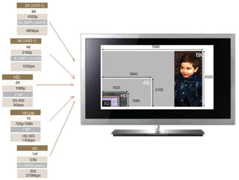
UltraHD does not obligatorily require a new video coding scheme, but considering the data rates required, it is certainly advantageous to introduce a video compression scheme that provides the desired quality while at the same time being more efficient than existing schemes. The International Telecommunication Union Telecommunications/International Organization for Standardization (ITU-T/ISO) specification H.265 is one such scheme, which we describe next.
H.265 is seen as a successor to H.264/MPEG-4 AVC. The work was started around 2006 by some of the pertinent committees; the worked picked up steam in 2010, and a stable working draft was developed by 2012 (see Figure 2).
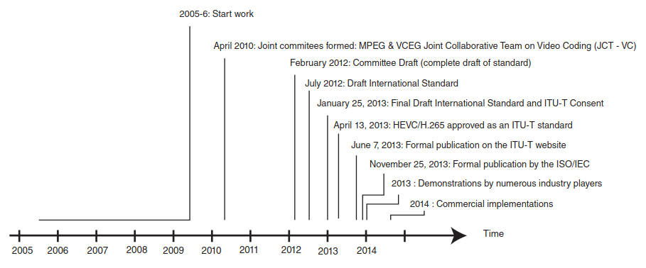
Key developers of the standard include but are not limited to ATEME, Comcast, CableLabs, Motorola, Sony, Mitsubishi, Harmonic, NBC, Cisco, NEC, LG, Microsoft, and DirecTv.
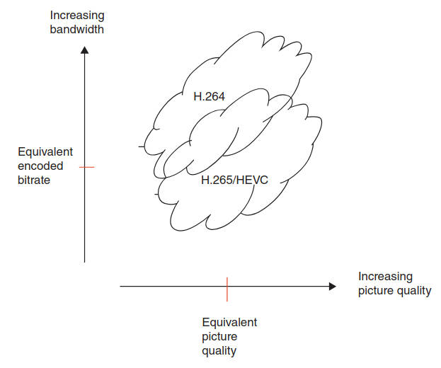
HEVC is (yet another) hybrid codec, with its main structure being similar to conventional hybrid codecs, but offering enhanced flexibility. The design goals were to achieve a compression gain of 50 % over H264/AVC, sustaining a maximum 10-fold increase in complexity for the encoder and a maximum 2/3rd increase in complexity for the decoder. The operative feature is that video can be compressed into a smaller size or bit rate; actual savings ranging from 30 % to 50 % have been cited in the literature (up to 2 × better compression efficiency compared to the baseline H.264/AVC algorithm); however, it also has increased computational complexity compared to H.264, requiring more advanced chip sets on all equipment utilizing this technology.
Figure 3 depicts the value proposition for HEVC.
Many demonstrations and simulations were developed in recent years, especially in 2013, and commercial-grade products are expected in the 2014–2015 timeframe, just in time for UltraHD applications. In fact, HEVC is designed to cover a broad range of applications for video content including, but not limited to, the following:
- Broadcast (cable TV on optical networks/copper, satellite, terrestrial, etc.);
- Camcorders;
- Content production and distribution;
- Digital cinema;
- Home cinema;
- Internet streaming, download, and play;
- Medical imaging;
- Mobile streaming, broadcast, and communications;
- Real-time conversational services (videoconferencing, videophone, telepresence, etc.);
- Remote video surveillance;
- Storage media (optical disks, digital video tape recorder, etc.);
- Wireless display.
Since HEVC provides superior video quality and up to twice the data compression as the previous standard (H.264/MPEG-4 AVC), the implications for satellite operators are that users (e. g., the Dish Network, DirectTV) may, in principle, require less transponder bandwidth to support the necessary video quality. Or that, considering the ever-increasing bandwidth growth driven by evolving applications such as UltraHD, users will either increase the video quality and retain the same transponder bandwidth, or possibly need more bandwidth when UltraHD services are implemented.
Video frames have intrinsic natural structures and/or repetitive patterns. Hence a pixel’s color can be predicted from the color of its neighbors within the same frame (intraframe, also known as “intra”) or from recent frames (interframe, also known as “inter”) – this is especially the case when motion is involved. The basic approach is to encode a block of pixels as a prediction mode plus a residual, or delta, from that prediction; the delta information is typically smaller (requiring fewer bits) than coding pixel values directly, thus achieving signal compression. Three patterns that are common in video frames are flat regions, smooth gradients, and straight edges. An advanced algorithm deals with these elements in an efficient manner.
Coded video content conforming to the HEVC recommendation uses a common syntax. To achieve a subset of the complete syntax, flags, parameters, and other syntax elements are included in the bitstream that signal the presence or absence of syntactic elements that occur later in the bitstream. The coded representation specified in the syntax is designed to enable a high compression capability for a desired image or video quality. The algorithm is typically not lossless, as the exact source sample values are typically not preserved through the encoding and decoding processes. A number of techniques may be used to achieve highly efficient compression; encoding algorithms (not specified per se in the standard) may select between inter and intra coding for block-shaped regions of each picture. Inter coding uses motion vectors for block-based inter prediction to exploit temporal statistical dependencies between different pictures.
Intra coding uses various spatial prediction modes to exploit spatial statistical dependencies in the source signal for a single picture. Motion vectors and intra prediction modes may be specified for a variety of block sizes in the picture. The prediction residual may then be further compressed using a transform to remove spatial correlation inside the transform block before it is quantized, producing a possibly irreversible process that typically discards less important visual information while forming a close approximation to the source samples. Finally, the motion vectors or intra prediction modes may also be further compressed using a variety of prediction mechanisms, and, after prediction, are combined with the quantized transform coefficient information and encoded using arithmetic coding. HEVC can support 8K UltraHD video, with a picture size up to 8192 × 4320 pixels.
Figure 4 depicts a HEVC-based coder.
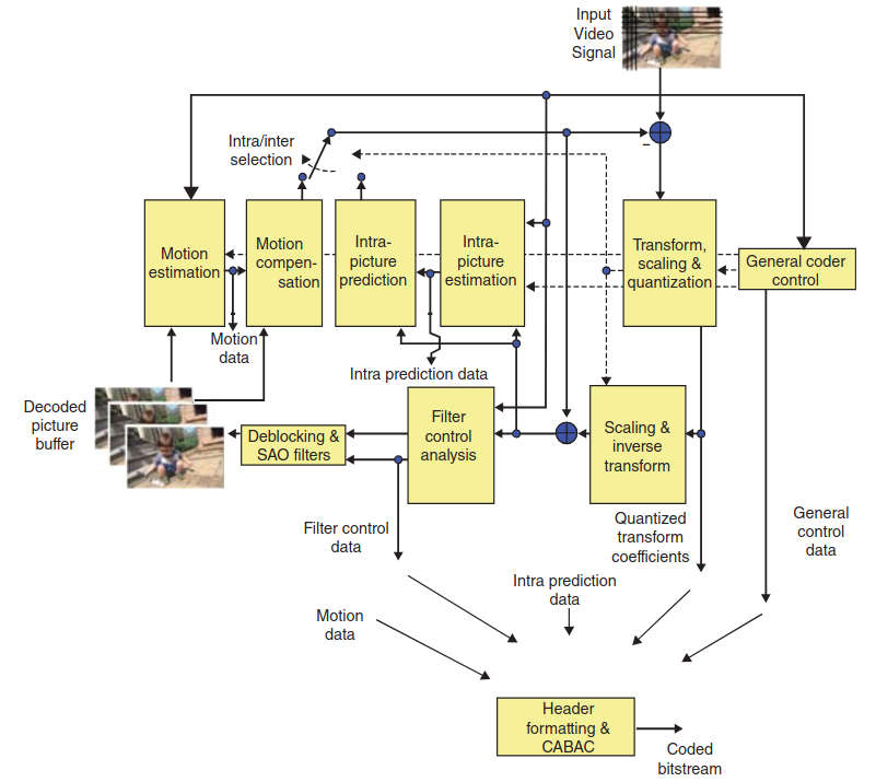
The algorithm provides a recursive quadtree structure for frame partitioning, larger block transforms, more efficient motion compensation and motion vector prediction, additional sample adaptive offset filtering, and an enhancement to Context-Adaptive Binary Arithmetic Coding (CABAC) called Syntax-Based Context-Adaptive Binary Arithmetic Coder (SBAC) (CABAC is used in H.264/AVC). Although improvements in data rate and/or picture quality are achieved, all these improvements significantly increase the encoding complexity and to some degree the decoding complexity; 1080p encodes are expected to be 5–10 times more taxing, while 4K video multiplies those demands by another 4 to 16 ×; it should be noted that the encoding processing can be parallelized, allowing a way to bring the computing time into an acceptable range (for both stored programming encoding and decoding, and for real-time encoding of live events).
Some of the key features of HEVC are:
- More flexible partitioning;
- Increased flexibility in prediction mode and transform block sizes;
- More sophisticated interpolation and deblocking filters;
- More refined prediction and signaling of modes and motion vectors;
- Ability to support parallel processing.
Figure 5 depicts the basic elements of the process in a satellite environment.
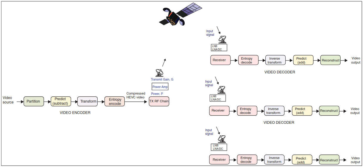
As can be seen in the figure, the H.265 encoder starts the process by partitioning the picture on a frame into a group of units. This is followed by a step of predicting each unit using interpolation or intrapolation prediction and then subtracting the prediction from the unit itself to create a “delta” residual signal (the residual is the difference between the original video unit material and the predicted unit video). The next step entails transforming and then quantizing the residual signal. The bit-stream thus generated is entropy-encoded, along with prediction information, mode information, and appropriate Moving Pictures Expert Group (MPEG) headers. The information is thus transmitted (this will entail adding the Forward Error Correction (FEC) and then modulating the underlying carrier). After the signal is received (the signal is demodulated and the FEC is consumed), the H.265 decoder handles the reverse process. The received stream is entropy decoded, and the elements of the coded sequence are extracted. The transformed signal is inverted and rescaled. The units are predicted, and the prediction is added to the output of the inverse transform. The final step is the reconstruction of the video image (combining the constituent units).
In HEVC (as in other ITU-T and ISO/IEC video coding standards), only the bitstream structure and syntax are standardized in addition to constraints on the bitstream and its mapping for the generation of decoded pictures. Table 1 provides the definition of some key terms used in HEVC.
| Table 1. Definition of Key Terms Used in HEVC (from Joint Collaborative Team on Video Coding of ITU-T SG16 WP3 Documents) | |
|---|---|
| Term | Definition |
| Access unit (AU) | A set of NAL units that are associated with each other according to a specified classification rule, are consecutive in decoding order, and contain exactly one coded picture. |
| Coded video sequence (CVS) | A sequence of access units. |
| Coding block | An N×N block of samples for some value of N such that the division of a coding tree block into coding blocks is a partitioning. |
| Coding tree block | An N×N block of samples for some value of N such that the division of a component into coding tree blocks is a partitioning. |
| Coding tree unit (CTU) | A coding tree block of luma samples, two corresponding coding tree blocks of chroma samples of a picture that has three sample arrays, or a coding tree block of samples of a monochrome picture, or a picture that is coded using three separate color planes, and syntax structures used to code the samples. |
| Coding unit (CU) | A coding block of luma samples, two corresponding coding blocks of chroma samples of a picture that has three sample arrays, or a coding block of samples of a monochrome picture, or a picture that is coded using three separate color planes, and syntax structures used to code the samples. |
| Context-adaptive binary arithmetic coding (CABAC) | An entropy encoding methodology (a lossless compression technique) used in H.264/MPEG-4 AVC video encoding as well as in the HEVC. It combines an adaptive binary arithmetic coding technique with context modeling, to achieve a high degree of adaptation and redundancy reduction. |
| DC transform coefficient encoding process | A transform coefficient for which the frequency index is zero in all dimensions. |
| A process not specified in this in HEVC that produces a bit stream conforming to the H.265 specification | |
| Inter coding | Coding of a coding block, slice, or picture that uses inter prediction. |
| Inter prediction | A prediction derived in a manner that is dependent on data elements (e. g., sample values or motion vectors) of pictures other than the current picture. |
| Intra coding | Coding of a coding block, slice, or picture that uses intra prediction. |
| Intra prediction | A prediction derived from only data elements (e. g., sample values) of the same decoded slice. |
| Network abstraction layer (NAL) unit | A syntax structure containing an indication of the type of data to follow and bytes containing that data. |
| Prediction | An embodiment of the prediction process. |
| Prediction block | A rectangular M×N block of samples on which the same prediction is applied. |
| Prediction process | The use of a predictor to provide an estimate of the data element (e. g., sample value or motion vector) currently being decoded. |
| Prediction unit (PU) | A prediction block of luma samples, two corresponding prediction blocks of chroma samples of a picture that has three sample arrays, or a prediction block of samples of a monochrome picture, or a picture that is coded using three separate color planes and, syntax structures used to predict the prediction block samples. |
| Predictive (P) slice | A slice that may be decoded using intra prediction or inter prediction using at most one motion vector and reference index to predict the sample values of each block. |
| Residual | The decoded difference between a prediction of a sample or data element and its decoded value. |
| Transform unit (TU) | A transform block of luma samples of size 8 × 8, 16 × 16, or 32 × 32; or four transform blocks of luma samples of size 4 × 4, two corresponding transform blocks of chroma samples of a picture that has three sample arrays; or a transform block of luma samples of size 8 × 8, 16 × 16, or 32 × 32; or four transform blocks of luma samples of size 4 × 4 of a monochrome picture or a picture that is coded using three separate color planes; and syntax structures used to transform the transform block samples. |
HEVC effectively doubles the data compression ratio compared to H.264/MPEG-4 AVC at the same level of video quality. The standard is ideally positioned for UltraHD TV displays and content capture systems that utilize progressive scanned frame rates; it efficiently supports display resolutions from Quarter Video Graphics Array (QVGA) resolution (320 × 240) all the way up to 4320p (8192 × 4320). In addition to more efficient data rates it provides improved picture quality as measured by noise level, color resolution, and dynamic range. Benchmarking firms were conservatively estimating at press time a 25–35 % lower bit rates at a given Peak Signal to Noise Ratio (PSNR).
To achieve these efficiencies, the HEVC specification provides a flexible frame representation mechanism by introducing the concepts of coding unit (CU), prediction unit (PU), and transform unit (TU). Individual video frames are partitioned into tiles (also known as slices), which are, in turn, partitioned again into units known as Coding Tree Units (CTUs), comparable to the macroblocks in MPEG-2/4 environments. Instead of H.264’s 16 × 16-pixel macroblocks, HEVC employs a CTU that can be as large as 64 × 64, describing less complex areas in the picture more efficiently.
The CTUs are the basic 64 × 64 pixel elements that comprise the basic unit of coding. CTUs are, in turn, subdividable in smaller squares known as CUs, which themselves are partitionable into one or more PUs. The PUs are employed to make the “predictions” using intra(frame) or inter(frame) prediction. In intra(frame) prediction, each PU is predicted from the neighboring image data in the same frame using DC prediction An averaging sample mode. DC informally refers to “direct current,” in the sense that a DC signal is a signal that has a constant value with no non-zero frequency content. So a DC intra prediction mode is a mode in which the prediction signal has a constant value.x (this uses an average value for the PU), planar prediction (this fits a plane surface to the PU), or directional prediction (this extrapolates from neighboring image data). In inter(frame) prediction, each PU is predicted from image data in one or two reference pictures (typically before and/or after the current picture in temporal order) using motion-compensated prediction.
The residual information that is present after the prediction difference is transformed into TUs utilizing a Discrete Sine Transform (DST) or a Discrete Cosine Transform (DCT). The block transforms applied against the residual information in each CU is 32 × 32, 16 × 16, 8 × 8, or 4 × 4 in scope. As noted, HEVC uses an enhancement to CABAC where the entropy coding of transform coefficients have been selected for a higher throughput than H.264/MPEG-4 AVC. A coded HEVC stream comprises quantized transform-resulting coefficients, prediction information (motion vectors and prediction modes), partitioning information, and header information. The entire bitstream comprising these data items is encoded using the CABAC.
In HEVC, intra coding supports 35 prediction modes: a planar mode, a DC mode, and 33 angular prediction modes. HEVC CTUs are an extension of the 16 × 16 luma samples macroblock in the AVC standard. A CTU encompasses 2N×2N luma samples, with N = 4, 8, 16, or 32 (luma is an adjective used in the standard represented by the symbol or subscript Y or L, specifying that a sample array or single sample represents the monochrome signal related to the primary colors). The larger CTUs support improved compression efficiency. Each CTU represents a top-level CU; each CU can be adaptively partitioned into four sub-CUs until a minimum size is obtained; this forms a recursive quadtree structure. The CU contains the PU that defines the prediction being made. With intra coding, the PU has the same size as a 2N×2N CU (a bottom-level CU with the minimum size contains four N×N PUs). The TU contains the transformation data. Adaptive transforms of 4 × 4, 8 × 8, 16 × 16, and 32 × 32 are supported.
Further to the discussion above, HEVC pictures are divided into coding tree blocks (CTBs); these appear in the picture in raster order. Depending on the stream parameters, the CBTs are 64 × 64, 32 × 32, or 16 × 16. Each CTB can be split recursively in a quadtree structure, all the way down to 8×8. For example, a 32 × 32 CTB can consist of three 16 × 16 and four 8 × 8 regions. These regions are called CUs. Thus, CUs can be 64 × 64, 32 × 32, 16 × 16, or 8 × 8. CUs are the basic unit of prediction in HEVC. The CUs in a CTB are traversed and coded in Z order. See Figure 6 for an example of ordering.
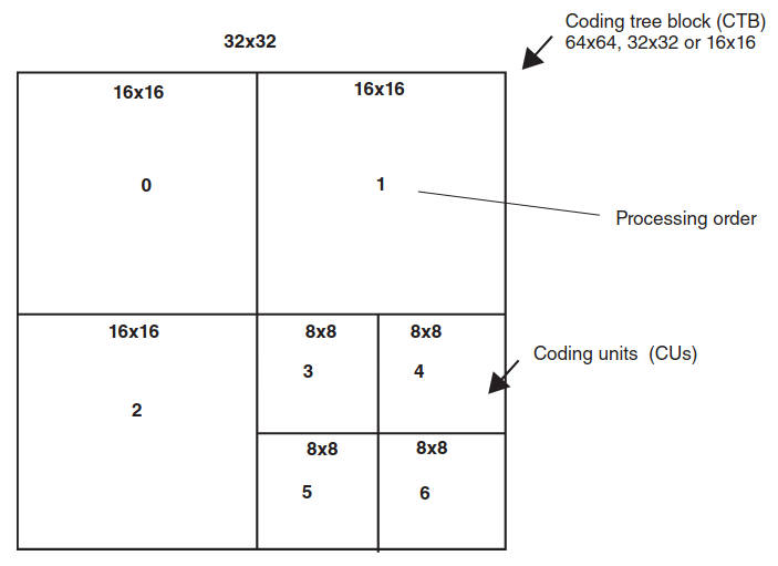
Each CTB is assigned a partition signaling to identify the block sizes for intra or inter prediction and for transform coding. The partitioning is a recursive quadtree partitioning. The root of the quadtree is associated with the CTB. The quadtree is split until a leaf is reached, which is referred to as the coding block. (When the component width is not an integer number of the CTB size, the CTBs at the right component boundary are incomplete; when the component height is not an integer multiple of the CTB size, the CTBs at the bottom component boundary are incomplete.) The coding block is the root node of two trees: the prediction tree and the transform tree. The prediction tree specifies the position and size of prediction blocks. The transform tree specifies the position and size of transform blocks. The splitting information for luma and chroma is identical for the prediction tree and may or may not be identical for the transform tree.
The blocks and associated syntax structures are encapsulated in a “unit” as follows:
- One prediction block or three prediction blocks (luma and chroma) and associated prediction syntax structures units are encapsulated in a PU;
- One transform block or three transform blocks (luma and chroma) and associated transform syntax structures units are encapsulated in a TU;
- One coding block or three coding blocks (luma and chroma), the associated coding syntax structures, and the associated prediction and TUs are encapsulated in a CU;
- One CTB or three CTBs (luma and chroma), the associated coding tree syntax structures, and the associated CUs are encapsulated in a CTU.
The following divisions of processing elements of the H.265 specification form spatial or component-wise partitionings (also see Figure 7):
- The division of each picture into components;
- The division of each component into CTBs;
- The division of each picture into tile columns;
- The division of each picture into tile rows;
- The division of each tile column into tiles;
- The division of each tile row into tiles;
- The division of each tile into CTUs;
- The division of each picture into slices;
- The division of each slice into slice segments;
- The division of each slice segment into CTUs;
- The division of each CTU into CTBs;
- The division of each CTB into coding blocks, except that the CTBs are incomplete at the right component boundary when the component width is not an integer multiple of the CTB size, and the CTBs are incomplete at the bottom component boundary when the component height is not an integer multiple of the CTB size;
- The division of each CTU into CUs, except that the CTUs are incomplete at the right picture boundary when the picture width in luma samples is not an integer multiple of the luma CTB size, and the CTUs are incomplete at the bottom picture boundary when the picture height in luma samples is not an integer multiple of the luma CTB size;
- The division of each CU into PUs;
- The division of each CU into TUs;
- The division of each CU into coding blocks;
- The division of each coding block into prediction blocks;
- The division of each coding block into transform blocks;
- The division of each PU into prediction blocks and;
- The division of each TU into transform blocks.
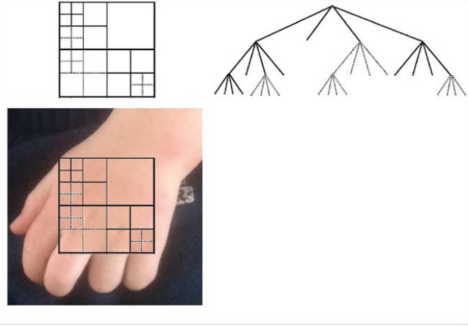
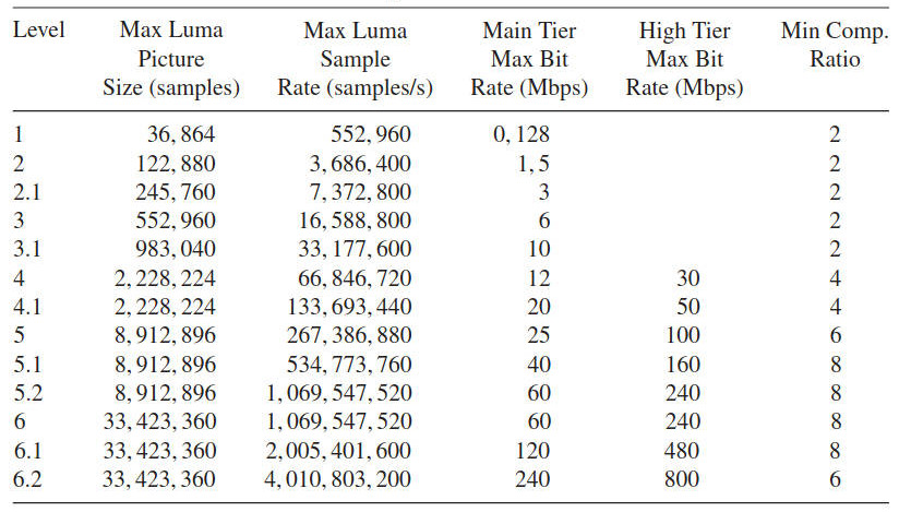
Table 2 compares HEVC with AVC. In some configurations HEVC also may generate high data rates; Table 3 depicts what the stream output can be, which is based on various standard profiles (as defined by Levels and Tiers).
| Table 2. A comparison Between Coding Schemes | ||
|---|---|---|
| HEVC | H.264/AVC | |
| Partition size | (Large) Coding unit 8×8 to 64×64 | Macroblock 16×16 |
 |  | |
| Partitioning | Prediction Unit | Sub-block down to 4×4 |
| Quadtree down to 4×4 | ||
| Square, symmetric, and asymmetric (only square for intra) | ||
| Transform | Transform unit square | Integer DCT 8×8, 4×4 |
| IDCT from 32×32 to 4×4 + | ||
| DST Luma Intra 4×4 | ||
| Intra prediction | 35 predictors | Up to 9 predictors |
| Motion prediction | Advanced motion vector prediction AMVP (spatial + temporal) | Spatial medium (3 blocks) |
| Motion precision | 1/4 Pixel 7 or 8 tap, 1/8 Pixel 4-tap chroma | 1/2 Pixel 6-tap, 1/4 Pixel bi-linear |
In summary, HEVC intra prediction mechanisms operates as follows: Frames are processed in 4 × 4 – 64 × 64 blocks of pixels in (mostly) top-left to bottom-right order; the algorithm can use the (previously processed) upper and left neighboring pixels to estimate (predict) the current block of pixels.
The video, as is normally the case, consists of 1 luma and 2 chroma streams (YC r Cb colorspace); 4:2:0 subsampling implies that the luma is at 2 × the x and y resolution. The prediction is done separately for all 3 streams.
The H.265 algorithm allows one to predict a block of pixels as:
- The average of its neighbors (DC mode; “direct current” analogy);
- A smooth gradient based on its neighbors (planar mode);
- A linear extension of its neighbors in one of 33 directions (angular mode).
A total of 35 total modes are available, increased from 8 in H.264. See Figure 8 for an illustration of the prediction modes.
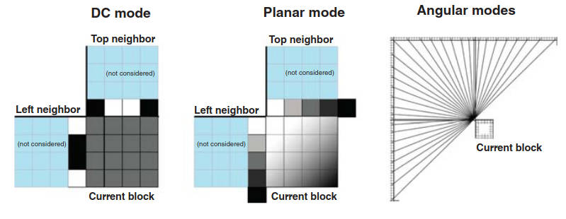
The DC mode predicts that all pixels in the block are the average of the edge pixels of top and left neighbor blocks; this is ideal for the compression of flat (one color) frame regions. The planar mode predicts that the block forms a smooth gradient defined by its top and left neighbors; it is computed by the averaging of two linear interpolations; this is ideal for the compression of smoothly varying frame regions.
The angular mode entails more coverage close to horizontal and vertical pixels (extend neighbor pixels into current block at specific angle); varying features along different directions (including areas with straight edges) are in fact common in actual video frames.
Figure 9 depicts the positioning of HVEC functionality in the transmission protocol stack.

Thus, HVEC affords higher coding efficiency than H.264 (as high as 50 %); it has higher complexity than H.264, allowing encoding and decoding to be parallelizable, but thus requiring faster chipsets; and it supports higher resolutions for evolving video applications (e. g., UltraHD).
The interested reader should directly consult the standard for additional information and detailed protocol specifics.
Bandwidth/Transmission Requirements
The bit rates required to support UltraHD can be very high, especially if full quality is desired. Uncompressed UtraHD would require more than 50 Gbps of bandwidth. No residences have such access capacity today, and the network transport/transmission of multiple channels of this type of video would be quite taxing, if not impractical. Urban users in highly developed regions may have access bandwidth in the 100–500 Mbps range, but most users even in advanced countries have less than 100 Mbps “entrance” facilities. Current compression technology would put the delivery of UltraHD in the 30–120 Mbps range per channel. A household watching, say, four independent simultaneous channels would need 120–480 Mbps, or the equivalent of an OC-3–OC-12 or a GbE service. That is why new compression techniques are highly desirable; roughly, a 50 % bandwidth saving is feasible with HVEC – however, we saw earlier that HEVC may still generate high data rates.
Proponents make the case that new capabilities and possibilities emerge as follows when afforded with a 50 % video transmission rate reduction compared with the status quo:
- Improvements for existing applications:
- IP Television (IPTV) over Digital Subscriber Line (DSL): potentially greater IPTV penetration;
- Greater deployment of Over The Top (OTT) and multiscreen services;
- Improved archiving facilities, including cloud-based services.
- Enablement of emerging services:
- Introduction of 1080p60/50 with bit rates comparable to 1080i;
- Support of immersive viewing experience (UltraHD 4K, 8K) both from stored media as well as from transmitted programming;
- Provision of premium services (sporting events, concerts, etc.) for home theaters, bars, electronic cinema.
Regarding HEVC, two sets of performance results are listed next, on the basis of data from industry assessments, particularly.
1 Comparisons have been made with H.264/AVC. A Joint Model (JM) reference software has been developed by the MPEG and VCEG Joint Video Team for H.264/MPEG-4 AVC to assess performance results. Versions JM 18.3 and 18.4 (High Profile) have been compared with HM 7 and 8 (Main Profile), assessing performance with video ranging from WVGA (Wide Video Graphics Array) to Full HD video sequences. Note: WVGA is any display resolution comparable to VGA but somewhat wider, for example, 720 × 480 pixels (3:2 aspect), 800 × 480 pixels (aspect ratio 5:3), 848 × 480 pixels, 852 × 480 pixels, 853 × 480 pixels, or 854 × 480 pixels (aspect ratio approximately 16:9) – WVGA is a common resolution used by LCD projectors. VGA video refers to the video achievable with display hardware first introduced with the IBM PS/2 line of computers in the late 1980s, later followed by widespread adoption as an analog computer display standard. Two indicators are assessed:
- Objective quality (PSNR-Bjontegaard benchmarking): an average bit rate savings of 35 % for entertainment applications has been validated. Coding performance increases with resolutions: >39 % for HD and beyond. In summary, average bit rate savings of 40 % for low delay applications (low delay) have been demonstrated (also see Figure 10; notice in the figure that to achieve a quality of a PSNR = 37 dB, for example, H.265 requires 2 Mbps, while H.264 requires 3 Mbps).
- Subjective quality (Mean Opinion Score): an average bit rate savings of 50 % for equivalent perceived quality have been demonstrated. For some (not as-dynamic 1080p) content savings from 30 % up to 67 % have been demonstrated.

2 Performance assessments for 4K native UltraHD content have been undertaken. Both H.264/AVC and HEVC encoders were tested, with Constant Bit Rate (CBR) outputs and equivalent Group of Pictures (GOPs); 4:2:0 sampling and 8-bit material were used. A 38–50 % bit rate savings were observed (PSNR-Bjontegaard benchmarking). The implications are that the observed gain would allow the broadcast of 4K UltraHD TV (50/60p) at video bit rates around 13 Mbps (as confirmed by subjective testing) and around 50 Mbps (SONET STS-1) for 8K UltraHD.
Table 4 summarizes and generalizes some of the results of this discussion (but rounds up the 4K/8K requirements to slightly more conservative targets).
| Table 4. Data Rates and System Capacity for Various Commercial TV Transmission Schemes | ||||
|---|---|---|---|---|
| Data rate for commercial TV distribution in Mbps | ||||
| SD | HD | 4K | 8K | |
| MPEG-2/H.263 | 4 | 20 | 80 | 320 |
| MPEG-4/H.264 | 2 | 10 | 40 | 160 |
| MPEG-4/H.265 | 1 | 5 | 20 | 80 |
| Number of commercial TV channels per 36 MHz transponder with DVB-2SX | ||||
| MPEG-2/H.263 | 25 | 5 | 1 | 0 |
| MPEG-2/H.264 | 50 | 10 | 2 | 0 |
| MPEG-4/H.265 | 100 | 20 | 5 | 1 |
| Number of commercial TV channels per a GbE (fiber) connection to the home (also for DOCSIS systems, e. g., 3.0) | ||||
| MPEG-2/H.263 | 250 | 50 | 10 | 3 |
| MPEG-2/H.264 | 500 | 100 | 20 | 6 |
| MPEG-4/H.265 | 1 000 | 200 | 50 | 12 |
| (assumes no Internet traffic on the connection) | ||||
| Number of commercial TV channels per a 10 GbE (fiber) connection to the home (also for DOCSIS systems, e. g., 3.1) | ||||
| MPEG-2/H.263 | 2 500 | 500 | 100 | 30 |
| MPEG-2/H.264 | 5 000 | 1 000 | 200 | 60 |
| MPEG-4/H.265 | 10 000 | 2 000 | 500 | 120 |
| (assumes no Internet traffic on the connection) | ||||
Note, as discussed earlier, that if content distributors just implement H.265 en bloc, without consideration to any UltraHD services, the number of transponders needed for a given bouquet of channels will be cut in half, thereby severely impacting the revenue stream to the satellite infrastructure providers (which is exactly what happened a few years ago when Germany converted its TV distribution from analog to digital: the number of satellite transponders needed went down by an order of magnitude).
Terrestrial Distribution
Naturally, for urban environments in developed countries, fiberoptic distribution of UltraHD can in principle be easily achieved, as seen in Table 4 when assessing typical fiber system capacities. However, both the actual plant upgrade to ascertain that all elements of the network (especially the last mile) support the higher speed(s), as well as the penetration per se throughout a given metropolitan area, may represent obstacles, or at least, retardant factors to the deployment of UltraHD TV. Suburban, exurban, and rural areas may find that satellite distribution is the only available choice.
In the context of terrestrial distribution, a short mention of Data Over Cable Service Interface Specification (DOCSIS) is made herewith. DOCSIS is a standard that supports the overlay of high-speed data transfer onto an existing hybrid fiber-coaxial (HFC) infrastructure used in a Cable TV system. DOCSIS was developed by Cable-Labs and other contributing companies in the 1990s.
Read also: Exploring the Future of Satellites
It has gone through a number of releases. DOCSIS 1.0 was released in 1997; it included basic elements from preceding proprietary cable modem products. DOCSIS 1.1 was released in 1999 incorporating additional standardization and quality of service (QoS) capabilities. DOCSIS 2.0 was released in 2001 with the objective of enhancing upstream transmission speeds. DOC-SIS 3.0 was released in 2006; the specification was revised to significantly increase transmission speeds (both upstream and downstream – in the 1 Gbps range). DOCSIS 3.1 was released in 2013, focusing on support capacities of at least 10 Gbps downstream and 1 Gbps upstream using 4096 Quadrature Amplitude Modulation (QAM); it does away with previous 6/8 MHz-wide channel spacing and uses smaller orthogonal frequency division multiplexing (OFDM) subcarriers that can be bonded inside a block spectrum (to about 200 MHz wide).
DOCSIS supports a number of Open Systems Interconnection (OSI) layers with 1 and 2 options, some of which are as follows:
- Physical layer channel width: All versions of DOCSIS up to 3.0 utilize either 6 MHz channels (e. g., North America) or 8 MHz channels (Europe, EuroDOC-SIS version) for downstream transmission over HFC plants. DOCSIS 2.0 is also used over microwave frequencies (10 GHz) in Ireland, and DOCSIS 1.x, 2.0, and 3.0 is also used for fixed wireless systems utilizing the 2,5–2,7 GHz MMDS microwave band in the United States;
- Physical layer modulation: All versions of DOCSIS specify the use of 64-level or 256-level QAM (64-QAM or 256-QAM) for the modulation of downstream data, utilizing the ITU-T J.83-Annex B standard for 6 MHz channel operation, and the DVB-C modulation standard for 8 MHz (EuroDOCSIS) operation. DOCSIS 2.0 and 3.0 also support 128-QAM with trellis coded modulation, and DOCSIS 3.1 adds 4096-QAM;
- Data link layer transmission: DOCSIS utilizes a mixture of deterministic access methods: TDMA for DOCSIS 1.0/1.1 and both TDMA and S-CDMA for DOCSIS 2.0 and 3.0.
Terrestrial transmission of UltraHD would use DOCSIS in the “distribution” side of the content delivery (not on the “contribution side”), that is, in the “last mile.”
Satellite Distribution
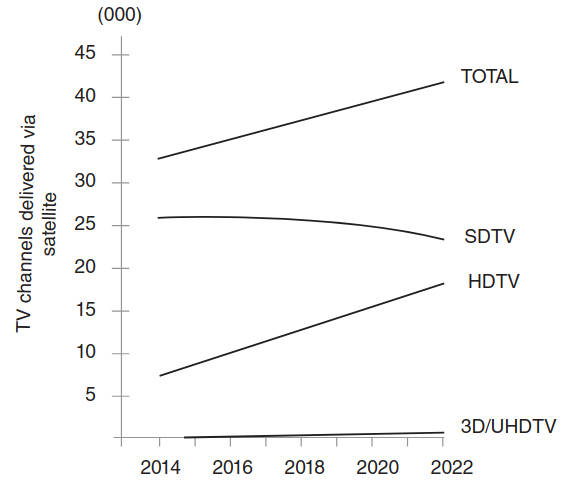
Satellite operators are planning to position themselves in this market segment, with some generally available broadcast services planned for 2020, and with more limited, targeted transmission starting at press time. However, the projections for the deployment of UltraHD are modest, and mass deployment is not expected to occur before 2023. The number of satellite TV signals distributed globally reached approximately 30 000 in 2013; market researchers expect the addition of 11 000 new satellite TV signals by 2023, with HDTV and emerging markets driving growth, but UltraHD still being “a drop in the bucket” at that time. See Figure 11, which is based on industry data.
DTH techniques, in particular, with High Throughput Satellites (HTS) and KA/KU Spot Beam TechnologiesHigh Throughput Satellites (HTSs) operation in the Ku or Ka are available to UltraHD distribution, consistent with the parameters of Table 4 and expanded in Table 5.
| Table 5. Satellite Distribution of UltraHD TV Channels | ||||
|---|---|---|---|---|
| Number of commercial TV channels per 24-transponder satellite with 36 MHz transponders operating with DVB-S2X | ||||
| SD | HD | 4K | 8K | |
| MPEG-2/H.263 | 600 | 120 | 24 | 0 (*) |
| MPEG-4/H.264 | 1 200 | 240 | 48 | 0 (*) |
| MPEG-4/H.265 | 2 400 | 480 | 120 | 24 |
| Note: tradeoffs will be needed between operating all 24 transponders at a fully-shared power level, or operating a smaller number of transponders at a higher power level (thereby improving reception quality) | ||||
| * Channel bonding could be employed (as discussed in DVB-S2 Modulation Extensions and Other Advances“Exploring DVB-S2 Modulation Extensions and Advances”) to support UltraHD in these situations – an upgrade to H.265 is a better strategy. | ||||
| Number of commercial TV Channels per 24-transponder satellite with H.265 and DVB-S2X and with a channel-type mix. | ||||
| Total Channels | 250 | |||
| % | Nominal bandwidth | |||
| SD channels | 20 | 50 | 50 000 000 | |
| HD channels | 70 | 175 | 875 000 000 | |
| 4K channels | 4 | 10 | 20 000 000 | |
| 8K channels | 6 | 15 | 1 200 000 000 | |
| 100 | 2 325 000 000 | |||
| Total channels | 400 | |||
| % | Nominal bandwidth | |||
| SD channels | 40 | 160 | 160 000 000 | |
| HD channels | 50 | 200 | 1 000 000 000 | |
| 4K channels | 8 | 32 | 640 000 000 | |
| 8K channels | 2 | 8 | 640 000 000 | |
| 100 | 2 440 000 000 | |||
| Total channels | 600 | |||
| % | Nominal bandwidth | |||
| SD channels | 75 | 450 | 450 000 000 | |
| HD channels | 15 | 90 | 450 000 000 | |
| 4K channels | 9 | 54 | 1 080 000 000 | |
| 8K channels | 1 | 6 | 480 000 000 | |
| 100 | 2 460 000 000 | |||
As an illustrative example, Eutelsat Communications provided the world’s first demo 4K channel in 2013 and launched in Europe in 2014 the first HEVC channel. As of press time, Eutelsat, working in partnership with ST Teleport, was planning to introduce its 4K TV channel on the EUTELSAT 70B satellite that reaches across Southeast Asia and Australia. The content displayed by Eutelsat’s new 4K channel is encoded in HEVC by ATEME and Thomson Video Networks at 50 frames per second with 10-bit color depth (one billion colors – HEVC Main 10 profile); it will be displayed on the Eutelsat stand at CommunicAsia 2014 using a Samsung 65 inch panel (UE65HU7500) and can be received directly by the latest consumer 4K TV panels equipped with DVB-S2 demodulators and HEVC decoders. The 4K TV channel is broadcasting a growing library of documentary, cultural and sports content filmed by television channels, production companies and Eutelsat to showcase the viewing experience of UltraHD.
Hybrid Distribution
Hybrid distribution, with satellite distribution complement by terrestrial transmission either over local cable/fiber facilities (e. g., a metropolitan area network) or by wireless technologies [WiMax, 3G/4G Long Term Evolution (LTE)], is always an option. One approach is for traditional distribution to receiving intermediate stations that offer caching (say a 4G/LTE or WiMax node), in turn using local distribution to the user community. This approach would work well, in particular, for nonlinear video.
Deployment Challenges, Costs, Acceptance
As discussed above, the introduction of HEVC elements throughout the video chain (content capture, content encoding, content storage/media, content transmission, content reception, and content display) is needed at the practical level to make UltraHD a reality. This will certainly have a nontrivial cost implication, not only in the production side, but also in the transmission side (with new encoders, transcoders, modulators, perhaps new wide-band transponders/spacecraft), as well in the reception side (new receivers/set-top boxes and new home display systems).
Following the limited adoption of 3D channels as alluded to earlier in this article, UltraHD is being introduced progressively alongside the value chain: TV producers and broadcasters (NHK) and video distribution providers (e. g., Eutelsat, Intelsat) with prevalence in cinema production. UltraHD may initially be a branding tool for the operator; at a later stage the operators will focus on premium subscribers. The time and significant capital investments required for broadcasters, producers, TV manufacturers, infrastructure owners, and consumers to upgrade to 4K are limiting factors for the immediate development of UltraHD TV services. Some were expecting the 2016 Olympic Games to represent a milestone for the launch of UltraHD channels. As noted above, currently, two 4K UHD channels could be broadcast on a 36MHz transponder; additional encoding improvements may occur over the next few years. These efficiency gains may likely result in the deployment of more TV channels, reducing video storage and distribution costs while maintaining or increasing the quality of the experience for the viewer.

