Delve into the intricacies of High Throughput Satellites (HTS) with our in-depth article. Uncover the fundamentals of multiple access schemes, frequency reuse, and the innovative spot beam approach. Learn about the various frequency bands, design considerations, and real-world applications of HTS technology.
- Overview
- Multiple Access Schemes and Frequency Reuse
- Spot Beam Approach
- Frequency Colors
- Frequency Bands of Operation
- Losses and Rain Considerations
- HTS Applications
- Comparison Between Approaches
- A View of Ku-based HTS Systems
- HTS Design Considerations
- Spot Beam Antenna Design Basics (Satellite Antenna)
- Single Feed per Beam Antennas
- Multiple Feeds per Beam Antennas
- Examples of HTS
- ViaSat-1 and -2
- EchoStar
- Eutelsat KA-SAT
- Intelsat EPIC
- Other Traditional HTS
- O3b
- Wideband Global Satcom (WGS)
This article Services, service options, and service providers change over time (new ones are added and existing ones may drop out as time goes by); as such, any service, service option, or service provider mentioned in this article is mentioned strictly as possible examples of emerging technologies, trends, or approaches. As such, it is intended to provide pedagogical value. No recommendations are implicitly or explicitly implied by the mention of any vendor or any product (or lack thereof ).x looks at High Throughput Satellite (HTS) technology, applications, and key design issues. Here, we discuss multiple access schemes and frequency reuse principles, followed by a discussion on the HTS spot beam approach, the frequency colors, the frequency bands of operation (specifically, the Ka band), the losses and rain considerations, and the typical HTS applications. A comparison between approaches, namely, a discussion on Ku-based versus Ka-based HTS systems, and some HTS design factors are provided. After some detailed spot beam antenna design basics information for the on-board satellite antenna, some examples of commercially deployed HTSs are provided.
A HTS can be defined as a satellite system that makes use of a large number of geographically confined spot beams distributed over a specified service area, offering a contiguous (or noncontiguous) covering The intuitive concept of coverage of an area with a set of spot beams is formalized in the mathematical concept of a “cover” of a topological space.x of that service area and providing high system capacity and user throughput at a lower net cost per bit. While most satellites in orbit operating at the Ku band currently provide large contoured coverages for video broadcast applications, there is an evolving market opportunity for satellites that provide broadband data services utilizing spot beams technology that employ Ka-band frequencies. Proponents make the argument that new high-capacity satellite systems are transforming the economics and quality of services that satellite broadband can provide; they see HTS as the future of satellite communications, “the wave of the future.”
In fact, the economics of HTSs enable service providers to offer Internet access services with data rates and monthly data download “gigabyte quotas” that are generally competitive with 4G/LTE wireless services, where these are available. The intrinsic concept of satellite spot-beam-based architectures goes back to at least 30 years, and a large number of patents have been issued on various aspects of the technology (see DVB-S2 Modulation Extensions and Other Advances“Partial Listing of System-Level us Patents for Spot-Beam/Multi-Beam Satellites” for an abbreviated listing).
This decade, however, is seeing advancement in the implementation and deployment of this technology on a scaled-up basis, specifically regarding the number of on-board spot-supporting feeds and the number of spacecraft with these designs. These advancements are driven by the growing worldwide demand for Internet services, especially in mobility environments, and by the orbital spectrum availability offered by the Ka band (although the Ku band is also being used to some extent for this and other related applications).
Traditional satellites have provided regional coverage at the C band and Ku band using one or a handful of service-supporting beams. The need for increased bandwidth – whether to support Direct to Home (DTH) video for High Definition (HD) channels (or eventually Ultra HD TV), or Internet access (including streaming video reception) – is driving operators to “new solutions” that combine high-density frequency reuse and new, less orbit-congested bands – specifically the Ka band – along with wider spectrum transponders. The reader should keep in mind that a traditional satellite that supports a payload of 24 C-band transponders (36 MHz each) and 24 Ku-band transponders (36 MHz each), only delivers a total of 1,7 GHz of capacity on the 48 transponders (48 × 36) in overlapping geographies, and, perhaps, two times as much if, say, two nonoverlapping regions are served (e. g., with a Ku-beam Continental US [CONUS] coverage from a satellite at 45 W along with a Ku-beam Western Europe coverage on the same spacecraft, for example, as was shown in Exploring the Future of Satellites“Architecture satellite regenerator, a transponder”).
Assuming that a 36 MHz transponder supports about 70 Mbps of data with DVB-S2, then this 1,7 GHz of capacity would achieve about 3 Gbps of total digital capacity (6 Gbps if two nonoverlapping regions are served). Even with DVB-S2X, the total bandwidth would be approximately 10 Gbps, which is the equivalent of a SONET (Synchronous Optical Network) OC-192 (STM 64). These data rates are mundane in the terrestrial fiber network environment, where OC-192 links are invariably common, as noted in the last section of Exploring the Future of Satellites“Trends, Technologies and Applications of Modern Satellites”.
If a frequency reuse of 24 times can be achieved with the 500 MHz allocated to the satellite, this can result in an effective capacity of 12 GHz or, say, 48 Gbps (OC-768, STM-256) on the spacecraft, which is a lot more desirable. In a somewhat parallel fashion, the utilization of small cells/frequency reuse is what enabled the terrestrial cellular industry to greatly increase their system-level throughput and support the avalanche of new 3G/4G smartphone users.
The primary currently-envisioned application for HTSs is high-speed/broadband Internet connectivity for mass markets; Figure 1 depicts a few examples of press time Ka HTS user terminals.
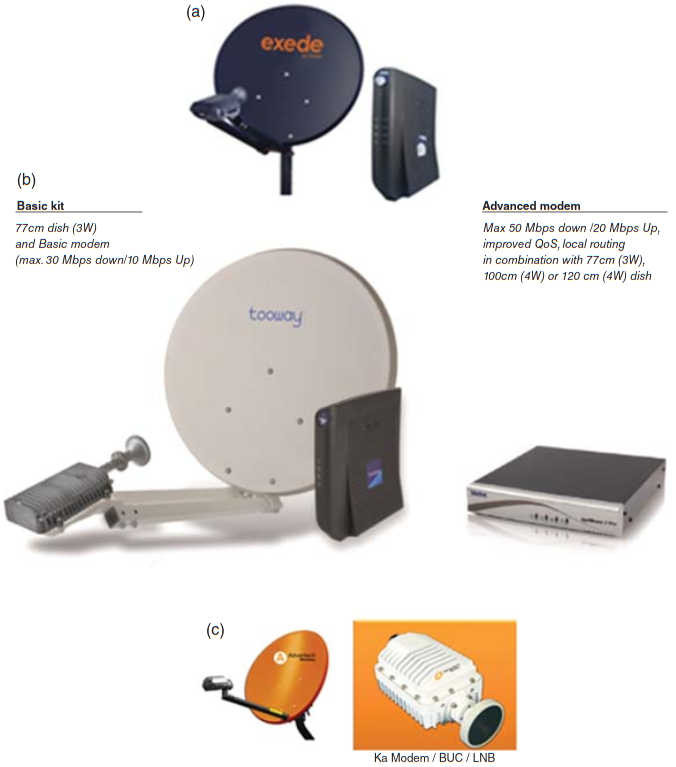
(a) Hardware with satellite service (ViaSat-1); (b) Eutelsat KA-SAT; (c) Advantech wireless equipment
Observers state that the total global bandwidth consumption is doubling every 2–3 years; hence, the deployment of HTS capabilities is a critical business imperative for satellite providers to remain competitive. The percentage of the world’s population using Internet was around 33 % at press time An estimated 2,5 billion people out of 7 billion have Internet access: about 80 % in North America, 70 % in Australia, 65 % in Europe, 45 % in Latin America, 40 % in the Middle East, 30 % in Asia, and 10–15 % in Africa.x, which suggests that there is a growth opportunity for service providers. For example, Africa is a continent where approximately 90 % of the citizens do not have Internet access – the continent has fiber optic cables spanning its coast, but little has been laid inland so far; hence, there is a dearth of infrastructure for Internet access, often limited to urban areas, and even then users have wired and wireless voice access that are barely capable of providing dial-up Internet access.
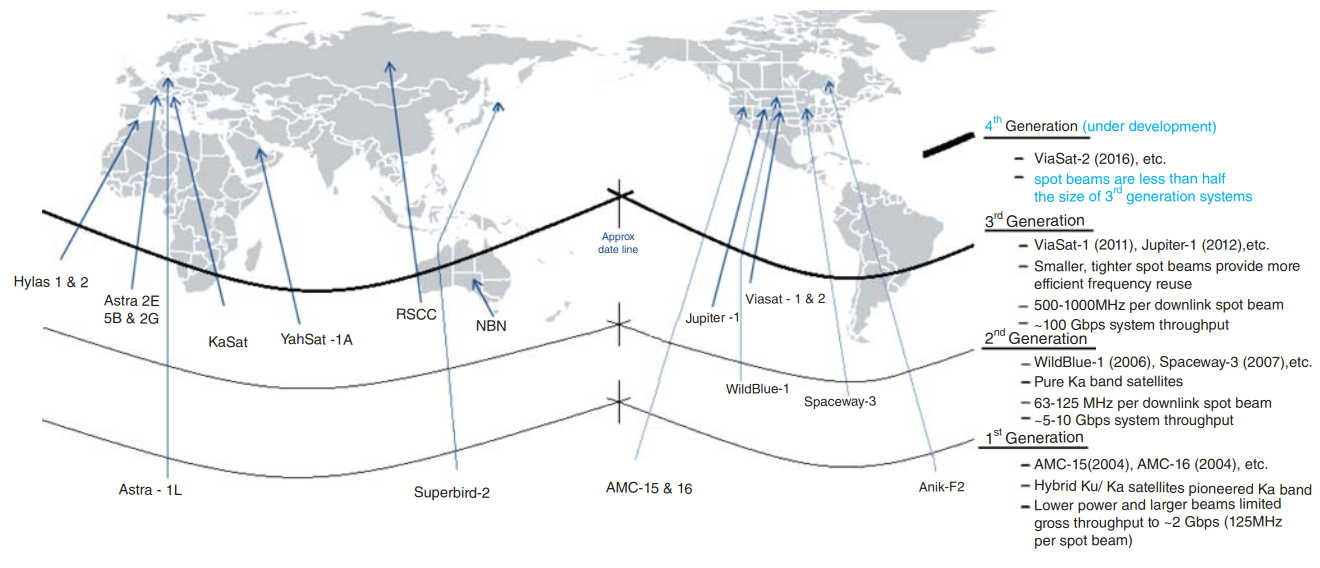
The latest HTSs typically deliver download speeds of more than 10 Mbps to individual customers and a single third-generation Ka-band HTS can support 2–3 million subscribers. Hence, HTSs can play an important role in the next few years, as terrestrial infrastructure develops. Since 2004, when HTSs were first put into service, many satellite operators have launched or are planning to launch Ka-based HTS. There have already been several generations of HTS in recent years (see Figure 2).

The vast majority of HTS systems utilize Ka band, with Thaicom, Insat, and Intelsat being the major exceptions that use Ku band. Platform vendors that supply the intrinsic on-the-ground technology include but are not limited to ViaSat, HNS, Gilat, NewTec, and Idirect.
For global HTS services, market research firms forecast that HTS capacity demand will increase to over 900 Gbps by 2022, while the emerging Medium Earth Orbit (MEO) HTS (MEO-HTS) segment will add another 100 Gbps of leased capacity demand as of 2022. For an example of a bandwidth driver, note that the European Union has set the goal of establishing 30 Mbps satellite coverage available to all EU citizens by 2020. The large majority of the forecasted bandwidth growth will be for HTS capacity to serve broadband access services (about 75 %); this is a “high-volume/low-margin” business that requires large amounts of low-cost bandwidth to maintain an acceptable service quality for subscribers – the per-Mbps price of HTS capacity is estimated to fall by over 40 % between 2013 and 2022, partly driven by increased price competition and gains in spectral efficiency through technological advancements.
Beyond that, for the other 25 % of the bandwidth growth, a combination of cell backhaul, Very Small Aperture Terminal (VSAT) networking, and IP trunking services will drive approximately similar quantities of HTS and MEO-HTS bandwidth demand globally, within the enterprise data segment. HTS and MEO-HTS capacity is also expected to compete for commercial and government mobility applications. In this context, a market-savvy approach for satellite service providers (as well as spacecraft manufacturers and satellite infrastructure providers) is to deliver a menu (and/or include mechanisms in the platforms to be able to deliver a menu) of service plans for different market segments, for example, in terms of different availability; the concept of different Service Level Agreements (SLAs) is intrinsically supportable with HTS-based approaches.
Overview
HTSs are an evolution of conventional spacecraft. When a satellite provides coverage of the entire region of the earth visible from the satellite utilizing a single beam, the gain of the satellite antenna is limited by the beamwidth. For a geostationary orbit (GSO) satellite, global coverage implies a 3 dB beamwidth of 17,5°, which in turn implies an antenna gain of about 20 dB; it follows that each user must be equipped with a relatively large aperture antenna to support a high traffic rate, impacting the cost and the practicality of deployment. Furthermore, only one stream of (multiplexed) information can be supported with a given frequency range (e. g., 36 MHz or even 500 MHz). To address this predicament, the spot beam The term multibeam (or multi-beam) is also used by some in lieu of the term spot beam (although that term can also be used – and is often used – for systems with just a handful of spot beams); we generally use the term spot beam (or spot-beam) in the context of HTSs.x approach has been widely utilized for satellite communication systems, but until recently typically only with a few beams (usually half-a-dozen to a dozen beams).
Spot beams are areas of discrete signal reception on the ground and discrete transmission reception in the spacecraft as implemented by supporting antenna structures. In spot beam satellite communication environments, the satellite provides coverage of only a portion of the earth, usually a nation or subcontinent, by using shaped narrow beams pointed to different geographic areas. The advantage of this approach is a higher satellite antenna gain following a reduction in the aperture angle of the antenna beam, which in turn implies that the user can employ a small aperture antenna The physics of antenna design dictate that for a given frequency, to generate higher gain, the antenna must be larger (which, of course, results in the smaller aperture angle); the smaller aperture angle is due to the fact that spacecraft utilize a few larger diameter reflectors, with a separate feed horn (or multiple feed horns) for each beam. Hence, in practical terms, it is the resulting higher gain of the antenna on the satellite that allows the use of smaller antennas by the user.x.
In addition, the multibeam technique supports the reuse of frequencies for different beams, thereby effectively increasing the total system capacity. However, it is well known that satellite power is a scarce resource; moreover, the traffic requirements of each beam may be different, perhaps because of time-zone differences (driving usage patterns); furthermore, it must be noted that when two (or more) beams utilize the same frequency, interbeam interference is introduced following the nonzero gain of the antenna sidelobes. Therefore, when there is interbeam interference between the beams, the capacity allocated to each beam is determined not only by the power allocated to the specific beam, but also by the power allocated to the other beams. As a result, it is critical to optimize the power allocation to each beam to meet the specific traffic demands. In spite of these general limitations, HTSs are designed to provide acceptable performance and system capacity.
Further along this topological coverage progression, with HTS, the service area is typically covered by many (up to 200 or more) edge-overlapping high-gain spot beams with frequency reuse to support interactive broadband services using small terminals. A high-count spot beam satellite, say, for a CONUS or Western European coverage, can provide about 10 times higher capacity than classical satellites using the same input power and similar receive-station antenna size. To enable increased user-accessible bandwidth and system throughput, HTS systems make use of the efficiency achievable with space division multiplexing as implemented with the use of spot beam. Thus, HTS achieve spectrum efficiency and enhanced performance through the use of spot beam antennas (often) in conjunction with ultrawideband (UWB) satellite transponders. The narrow beamwidths intrinsic with spot beams are achieved by employing antenna structures that focus downlink energy to distinct (but small) areas on the earth’s ground surface and have large areas for collecting uplink energy. User-to-Internet or user-in-beam-A-to-user-in-beam-B communication is then achieved with one (or more) terrestrial gateway node(s).
HTS spacecraft can operate at the Ku band, but recent implementations are principally at the Ka band (Ku-band HTSs include but are not limited to Intelsat 29E/EPIC, with 25–60 Gbps throughput); they can be in the nongeosynchronous orbit (non-GSO), but principally they are in the GSO. In general terms, the reason why most HTS operate at Ka band is because:
- It is relatively difficult for global operators to secure Ku-band orbital slots in various parts of the world, and;
- The Ka band offers more assigned spectrum bandwidth (upward of 1,1 GHz).
Multiple Access Schemes and Frequency Reuse
Before proceeding with additional discussion of HTS systems, we provide a quick review of multiplexing and multiple access schemes used in satellite communication. Readers who are familiar with these concepts may opt to skip to the next section.
Multiplexing, the ability to support multiple users over a single facility (e. g., a radio channel, a satellite band, a transponder) is as fundamental to communications as modulation. Multiple access protocols are channel allocation schemes that have desirable performance characteristics.
Key types of multiple access schemes are:
- Space Division Multiple Access (SDMA) (also known as Space Division Multiplexing).
- Frequency Division Multiple Access (FDMA) (also known as Frequency Division Multiplexing).
- Time Division Multiple Access (TDMA) (also known as Time Division Multiplexing).
- Code Division Multiple Access (CDMA) (also known as Code Division Multiplexing).
- Random Access. The use of algorithms that support randomized transmission in a distributed system without central control.
At the highest level of the multiple access protocols classification, one has two categories: conflict-free protocols and contention protocols. Conflict-free protocols are those ensuring a transmission, whenever initiated, which is a successful one, that is, will not be interfered by another transmission. In conflict-free protocols the channel is allocated to the users without any overlap between the portions of the channel allocated to different users. The channel resources can be viewed from a time, frequency, or mixed time-frequency perspective. The channel is allocated to the users either by static or dynamic techniques. The channel can be “divided” at the Physical Layer (of the Open Systems Interconnection Reference Model) by giving the entire frequency range (bandwidth) to a single user for a fraction of the time as done in TDMA, or by giving a fraction of the frequency range to every user all of the time as done in FDMA, or by providing every user access to the bandwidth at varying frequency or time “minislots” by utilizing spread spectrum mechanisms such as CDMA. Dynamic allocation (in the conflict-free protocols context) assigns the channel on the basis of demand (and/or reservation) such that a user who happens to be idle uses only little of the channel resources, leaving the majority of the bandwidth to the other, more active users. Such an allocation can be done by statistical multiplexing at the Data Link Layer (of the Open Systems Interconnection Reference Model).
One of the drawbacks of conflict-free protocols is that idle users do consume (an assigned) portion of the channel resources, unless a more complex Data Link Layer mechanism is used; this becomes a major issue when the number of potential users in the system is large. In systems with contention schemes, a transmitting user is not guaranteed to be instantaneously successful (retransmissions may be needed); however, they are more bandwidth-efficient. The best way to actually achieve dynamic allocation in the “modern era” would be to assign the satellite bandwidth (say a saturated transponder) as a high-capacity IP trunk where different users contend for resources at the packet layer, rather than nailing down bandwidth to users whether they needed it (at that instantaneous moment) or not; good traffic management techniques would (effectively) guarantee that all users receive adequate service levels (in throughput, latency, packet loss, and so on). An increasing number of broadcast-grade video these days is in fact being transmitted using Multiprotocol Label Switching (MPLS) IP-based services (at least terrestrially).
Space division multiplexing (also known as frequency reuse) is the ability to use the same frequencies (and/or polarizations) repeatedly across a system, but where there is geographical and/or physical separation. Space division multiplexing is a method of allowing multiple users to share a single communications channel by arranging the users so that they are not in one another’s communications range. Spectrum is a valuable resource, both in the satellite arena as well in the terrestrial wireless arena. In any frequency band (C, Ku, Ka), there is a limited amount of spectrum available, hence that spectrum must be utilized efficiently. A well-known approach is to employ frequency reuse, where a single satellite uses the same frequency multiple times simultaneously (frequency reuse is also intrinsically employed in satellite communications when multiple/all C-band satellites around the world use the C band, and multiple/all Ku satellites use the Ku band, etc.).
It is a method whereby a number of entities use a single service capability by having amounts of physical space within the service facility dedicated for their individual use. Thus, it should be noted that the method is used both across multiple satellites (at different orbital locations) as well by a single satellite illuminating discrete nonadjacent geographies with the same frequency. Frequency reuse is a concept that is used both terrestrially (e. g., cellular networks) and on satellites. For example, the radio FM band and the over-the-air TV band are reused in localities that are 75+ miles apart. Cellular phone frequencies also make use of this technique. The use of a C-band frequency by two earth stations using two C-band satellites is another example of space division multiplexing.
To go back to the single satellite use of space division multiplexing, the more frequency reuse supported by that single satellite, the greater the total system-level throughput that spectrum can achieve with that satellite. Satellite operators have implemented frequency reuse in their satellites for several decades in traditional (widebeam) applications. HTSs make extensive endogenous use of space division multiplexing, as implemented via fractional-degree spot beam coverage (and supporting antenna structures). As discussed already, HTSs support high overall throughput: the design goal is for satellite capacity to be in hundreds of gigabits per second (Gbps) compared to a few Gbps for Fixed Satellite Services (FSS) satellites. For example, ViaSat-1 launched in early 2012 has a total throughput capacity of 140 Gbps. Following the argument used in the introductory section, a satellite with 60 beams has an equivalent throughput of 30 GHz (30 times the amount of spectrum of a single beam satellite – 500 MHz on each polarity on a given band), or 30 × 4 = 120 Gbps (or, 150 Gbps, if 5-bit MODCODs are used).
TDMA is a communications technique that uses a common channel (multipoint or broadcast) for communications among multiple users by allocating unique time slots to different users. TDMA is used extensively in satellite systems, although it is employed in other environments as well. TDMA is multiple access technique whereby users share a transmission medium by being assigned and using (each user at a time and for a limited time interval) a number of time division multiplexed slots (subchannels); several transmitters use the same overall channel for sending several bit streams. In TDMA a channel (of a given bandwidth – typically a transponder) is shared by all the active remote stations, but each is permitted to transmit only in predefined short bursts of time (slots) allocated by a predetermined sequencing mechanism, thus sharing the channel between all the remote stations by dividing it over time (hence, time division). Therefore, in TDMA, the entire bandwidth is used by each user for a fraction of the time.
FDMA makes use of frequency division to provide multiple and simultaneous transmissions to a single transponder. Frequency division multiplexing (FDM) is the approach of deriving two or more simultaneous, continuous channels from a transmission medium by assigning a separate portion of the available frequency spectrum to each of the individual channels. Hence, in FDMA, the bandwidth of the available spectrum is divided into separate channels, with each individual channel frequency being allocated to a different active remote station for transmission. FDMA splits the available frequency band into smaller fixed frequency channels, and each transmitter or receiver uses a separate frequency. In FDMA, a fraction of the frequency bandwidth is allocated to every user all the time. Transmitters are narrowband or frequency-limited. A narrowband transmitter is used along with a receiver that has a narrowband filter so that it can demodulate the desired signal and reject unwanted signals, such as interfering signals from adjacent radios. In satellite communications, FDM is used to define the 12 (24 with polarization) transponders; however, the use of FDMA within a transponder is on the decline (with TDMA being the leading approach, as noted). (Some call this arrangement Frequency-Time Division Multiple Access [FTDMA]).
Satellites make use of all three of these techniques effectively: space division multiplexing is supported when multiple beams are employed over different regions while using the same frequency band among the different spot beams; frequency division multiplexing is used when allocating different transponders to different users or channels or functions; time division multiplexing is used when saturating a transponder with a single large carrier that comprises a stream of different dedicated digital channels.
CDMA is a coding scheme where multiple channels are independently coded for transmission over a single wideband channel. In some communication systems, CDMA is used as an access method that permits carriers from different stations to use the same transmission medium by using a wider bandwidth than the individual carriers. On reception, each carrier can be distinguished from the others by means of a specific modulation code, thereby allowing for the reception of signals that were originally overlapping in frequency and time. Thus, several transmissions can occur simultaneously within the same bandwidth, with the mutual interference reduced by the degree of orthogonality of the unique codes used in each transmission.
CDMA is an access method where multiple users are permitted to transmit simultaneously on the same frequency. The channel (probably derived via FDM methods), however, is larger than otherwise would be the case. Channelization is added, in the form of coding. In a CDMA system, all users access the same bandwidth, but they there are distinguished (separated) from one another by a uniquely different coding parameter. Each user is assigned a code that is utilized to transform the user’s signal into spread-spectrum-coded version of the user’s data stream, typically using Direct Sequence Spread Spectrum (digital) techniques. The receiver then uses the same spreading algorithm and code parameter to transform the spread-spectrum signal back into the original user’s data stream. Users time share a higher-rate digital channel by overlaying a higher-rate digital sequence on their transmission. A different sequence is assigned to each terminal so that the signals can be discerned from one another by correlating them with the overlaid sequence.
In static channel allocation strategies channel allocation is predetermined (typically at system design time) and does not change during the operation of the system. For both the FDMA and the TDMA protocols, because of the static and fixed assignment, parts of the channel can be idle even though some other users in the system may have data to transmit. As noted, dynamic channel allocation protocols attempt to overcome this by changing the channel allocation on the basis of the current demands of the users.
Static conflict-free protocols such as the FDMA and TDMA protocols do not utilize the shared channel very efficiently, especially when the system is lightly loaded or when the loads of different users are asymmetric. This is one of the motivations for random access schemes. In the satellite context, this approach is typically used in VSAT environments. Most random access schemes (contention-based multiple access protocols) are noncentralized protocols where there is no single node coordinating the activities of the others (although all nodes behave according to the same set of rules). Contention schemes do not automatically guarantee successful transmission.
When contention-based multiple access protocols are used, the necessity arises to resolve the conflicts, whenever they occur. Both static and dynamic resolutions exist. Static resolution means that the actual behavior is not influenced by the dynamics of the system. A static resolution can be based, for example, on user IDs or any other fixed priority assignment, meaning that whenever a conflict arises the first user to finally transmit a message will be the one with, say, the smallest ID (this is done in some tree-resolution protocols). A static resolution can also be probabilistic, meaning that the transmission schedule for the interfering users is chosen from a fixed distribution that is independent of the actual number of interfering users, as is done in Aloha-type protocols and the Carrier Sense Multiple Access (CSMA) protocol used in classical Ethernet systems. Dynamic resolution, namely, taking advantage and tracking system changes, is also possible in contention-based protocols. For example, resolution can be based on the time of arrival, giving the highest (or lowest) priority to the oldest message in the system. Alternatively, resolution can be probabilistic but such that the statistics change dynamically according to the extent of the interference.
The Aloha family of protocols is popular because of its seniority, as it is the first random access technique introduced; also, many of these protocols are simple and the implementation is straightforward. The Aloha family of protocols belongs to the contention-type or random retransmission protocols in which the success of a transmission is not guaranteed in advance. The reason is that whenever two or more users are transmitting on the shared channel simultaneously, a collision occurs and the data cannot be received correctly. This being the case, packets may have to be transmitted and retransmitted until eventually they are correctly received. Transmission scheduling is therefore the focal concern of contention-type protocols. Because of the great popularity of Aloha protocols, analyses have been carried out for a large number of variations (e. g., unslotted Aloha, slotted Aloha, and many others).
Spot Beam Approach
HTS systems can be classified as follows:
- Ka-band small spot beam systems;
- Ka-band large spot beam (widebeam) systems;
- Ku-band spot beam systems.
In the 1990s, some satellite operators endeavored to offer Ka-band capacity using a small Ka-band payload on satellites that were primarily C– or Ku band focused; the Ka-band beam was typically a wide-area beam with little or no frequency reuse – this wide-area beam approach had limited commercial appeal. New approaches were used in the decade that followed. This came about (under the thrust of market interest in interactive Internet access) because the total cost to design, construct, and launch a satellite is approximately the same whether the satellite is optimized for capacity (many beams) or for coverage (a few beams). To achieve a high degree of frequency reuse, the broader geography of interest is no longer covered by a large single beam, but by a high number of slightly overlapping, high-gain spot beams (however, user-to-user communications requires a dual-hop intervention of the gateway). As a result, the cost per delivered bit for the HTS design is significantly lower than for a satellite optimized for large broadcast coverage.
Each spot beam reuses available frequencies (and/or polarizations), so that a single HTS spacecraft can provide up to approximately 10 times the capacity of traditional satellites – channel frequencies are reused numerous times in geographically nonoverlapping spots, but the spectrum of the individual beams is constrained within the available satellite bands, typically 500 MHz (1 100 MHz in some circumstances) in total. HTS payloads commonly have 5–10 GHz of aggregate internal transponder bandwidth to support the combined throughput. These spot beams provide high signal strength and signal gain (Effective Isotropically Radiated Power [EIRP] and G/T), allowing the satellite to close links to small aperture earth stations at high data rates with reasonable rain fade margin, to provide acceptable overall link availability. Spot beams may be steered or may be fixed relative to the satellite.
There is no theoretical limit to the number of times that the spectrum can be reused (by achievable polarization discrimination purity and beam isolation); in practical terms, however, the number is limited by the size, weight, and complexity of the satellite antenna. A HTS spacecraft may have beams of different sizes; for example, it might have 60 0,40-degree beams and 40 0,80-degree beams. HTS leverages frequency reuse across multiple narrowly focused spot beams as compared to traditional satellite technology, which is based on a wide-coverage single beam (a few thousand miles), or at most a handful of beams (e. g., 6 beams). Each HTS spot beam covers an area 1–2 % the size of a conventional satellite beam; beams are typically 70–100 miles in diameter (each beam generally covers a few thousand square miles), but the size can vary as needed. Because the spot beams have limited geographic coverage, HTSs typically have gateway beams and transponders dedicated to supporting connections with gateway nodes on the ground, where the traffic is handed over to the Internet or some other network.
The first commercial HTS was IPSTAR (also known as Thaicom 4), which operated in the Ku band. The first wave of Ka HTSs was launched in the mid-2000s with spacecraft such as AMC 15/16, WildBlue-1 (first dedicated HTS in North America), and Telesat’s Anik F2, among others (Generation 1 and 2). A second wave was launched in the mid-2010s with spacecrafts such as ViaSat-1 and -2, KA-SAT (the first dedicated HTS in Europe), YahSat-1A and -1B, and RSCC, among others (Generation 3 and emerging Generation 4). These newer satellites tend to use Ka-band frequencies in the FSS mode. There are additional HTS projects either under construction or planned as of press time. Each of these succeeding generations of spacecraft has increased the number of beams and, thus, the derivable system-level throughput. The HTSs placed in service at the beginning of the decade have a download speed for the individual customer of more than 10 Mbps (examples of these are ViaSat-1 and KA-SAT platforms – these have also been called third-generation broadband VSAT systems, in contrast to second-generation VSAT systems that typically have a download speed to the individual customer up to 3–5 Mbps) (see Figure 3).
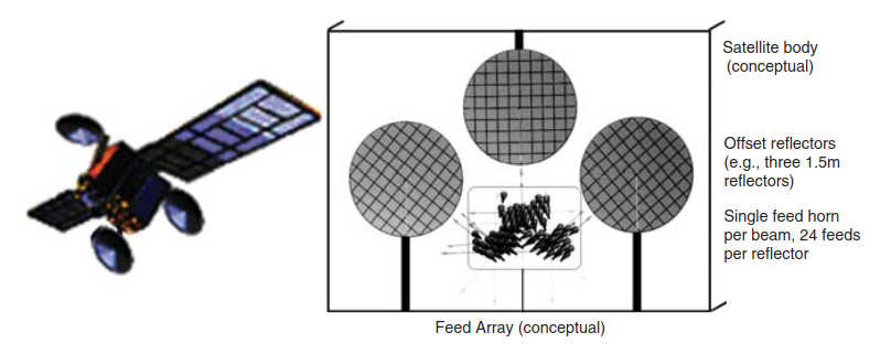
The satellite antenna system is a critical element for the realization of a multiple spot beam coverage environment with overlapping spots. A basic HTS approach is to use a specified number of feed horns in space (say 24) fitted on a geometric matrix and illuminating a single reflector (a spacecraft may, in fact, have multiple such arrangements of feeds and reflectors, say three or four or more). Beam-forming techniques are more sophisticated approaches than static arrangements, whereby multiple feed horns are energized with signals constructed on a “network,” called beam-forming network (BFN), to alter the phase of the distinct feeds such that constructive interference can be used to generate either a large shaped beam (shaped to a specific geography) or a pattern of spot beams. If a dynamically reconfigurable pattern is desired, then BFNs can be used as a core component of the multiple beams antennas; however, BFNs add weight and complexity BFNs can and have been used to on spacecraft antennas to design geographic-specific coverage; shaped reflectors are a simpler way to achieve the desired geographic patterns at lower cost/complexity, but once designed they cannot be altered; this is a drawback if the operator at some point desires to drift the satellite to a new (distant) orbital position to cover a new geography.x.

Specifically, two implementation approaches are possible for the HTS satellite antenna(s):
- Single feed per beam (SFB) and;
- Multiple feeds per beam (MFB).
SFB designs use one feed horn for each spot; this implementation enjoys hardware simplicity and achieves a modestly better electrical performance compared with the MFB, but at the expense of an increased number of reflectors (apertures). To provide overlapping spots, several reflector apertures, typically four, are required (in some instances it is also possible to create a four-color scenario using only three reflectors). SFB antennas represent the state of the art for spot beam systems (see Figure 4 for a model of such antenna with 10 CONUS beams, e.g., AMC 15/16 – non-CONUS beams supported with other antennas).
MFB designs use small subarrays for each spot; adjacent spots share some of the array elements. In this case, overlapping feed arrays are created, which allow producing overlapping spots using a single reflector aperture. The elements of the array are energized by a complex orthogonal BFN mentioned earlier.
Technologies such as phased array antennas and ground-based beam forming (GBBF) allow altering the coverage and the beam shape; this implies that satellite operators who consider deploying these technologies will be able to increase the capacity allocated to a beam. Phased array antennas are widely deployed in military systems, and GBBF are used in MSS constellations; however, significant additional costs on the spacecraft (phased array) or ground segment (for GBBF capabilities) have led to limited deployment of these technologies in the HTS market so far (we cover GBBF in Aeronautical Mobility Services“Key Technologies and Innovations of Aeronautical Applications”). Additional antenna information is provided below.
The salient aspects of HTS, as synthesized from the discussion above, are: the satellite antenna of these HTSs are characterized by many small beams with high gain (up to about 200 in the most recent systems), which allows for closing the link to relatively small user terminals; these satellite antennas also allow for multiple frequency reuse, resulting in a throughput in the range of hundreds of Gbps. The small diameter earth station antennas require adequate spacing of the GSO satellites to avoid interference. The saturated power (EIRP) at beam edge is typically in the 45–50 dBW range; the nominal bandwidth is 72- or 108 MHz at Ku band, and possibly even higher at Ka band where a typical HTS has a number of UWB transponders distributed among the various beams. UWB transponders on HTS may, in fact, operate at 100-, 250-, or 500 MHz; they can support a single carrier or multiple carriers. For example, Anik F2, a Boeing 702 spacecraft, uses a half dozen wideband 492-MHz transponders to transmit traffic to gateways in the United States and Canada. Wideband modulators supporting up to 475 Msymbols/s (MSps) (up to 1,85 Gbps throughput) have appeared on the market, enabling one to maximize throughput on single beam, without requiring any additional backoff. For the end user, HTS provides the capability to increase data rates, upward of 100 Mbps to a single site in some cases, and to improve application performance compared to traditional satellite services.
Frequency Colors
As noted, HTSs have a large number of beams making heavy use of frequency reuse, employing frequency reuse concepts partially similar to small-cell cellular telephony. The beams can be arranged in a honeycomb to provide coverage of a service region.
Figure 5 depicts, in general, the concept of multibeam for a CONUS coverage. A number of distinct frequencies are employed; in fact, both frequency differentiation and polarization differentiation can be utilized among neighboring beams.
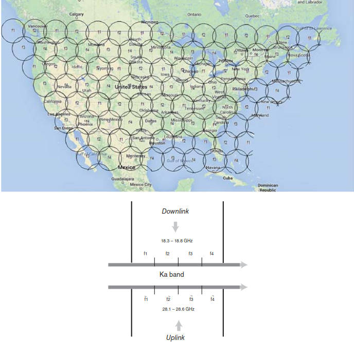
For example, a system could use:
- f1 = first quarter of the Ka bandwidth;
- f2 = second quarter of the Ka bandwidth;
- f3 = third quarter of the Ka bandwidth;
- f4 = fourth quarter of the Ka bandwidth;
or, the system could use:
- f1 = first half of the Ka bandwidth and right-hand circular polarization;
- f2 = second half of the Ka bandwidth and right-hand circular polarization;
- f3 = first half of the Ka bandwidth and left-hand circular polarization;
- f4 = second half of the Ka bandwidth and left-hand circular polarization).
Other frequency reuse schemes are possible, on the basis of the amount of spectrum available and the amount of spectrum serving a given area. The concept of the Four Color Theorem (4CT) is used. The term “color” is used to discuss different nonoverlapping (or noninterfering by using different polarizations) frequency bands, clearly with a reference to the mathematical concept of the 4CT The 4CT states that on a planar map, four colors are always sufficient to color a map such that no two adjacent “countries” sharing an edge boundary are of the same color – in fact, three colors are generally sufficient, but some complex/synthetic maps may need four (natural maps requiring four colors are rare). (The coloring has to be done “right”; however, situations may arise where more colors are needed.) For a long time this was a “known empirical fact” and it remained a mathematical conjecture; it took mathematicians over a hundred years to prove the theorem (from 1852 to 1976). The proof remains somewhat controversial even today because it entails having to use computer-assisted mechanisms for the analysis (more recently, theorem-proving software was used) in showing that there is a particular set of 1 936 maps, each of which cannot be part of a smallest-sized counterexample to the 4CT; any map that could be a counterexample must have a portion that looks like one of these maps. Since no smallest counterexamples exist, because any such example must contain one of these 1 936 maps, the contradiction in the logical argument implies there are no counterexamples and that the theorem is thus true.x. As noted, the “four colors” can be supported with two different frequency subbands within the full Ku or Ka band and two orthogonal polarizations (usually right-hand and left-hand circular at Ka, vertical, and horizontal at Ku) (e. g., refer to Exploring the Future of Satellites“Architecture satellite regenerator, a transponder” for a view of subbands).
Adjacent spots are of different “colors,” differing in frequency or polarization; hence, they can support the transmission of different information without mutual interferences. Spot beams with the same color use the same frequency and the same polarization, but they are spatially isolated from one another; no spot has a neighbor with the same color: because of the spatial separation, spot beams with the same color can support the transfer of different information. In most cases, the four-color approach is the best compromise between system capacity and performance; however, other frequency reuse schemes can also be utilized. Some HTS systems have optimized the total capacity at the expense of wide area coverage, because of the on-board antenna geometries used. Newer HTS systems are designed to double the bandwidth economics of earlier generations and simultaneously provide much larger coverage areas (e. g., ViaSat-2 will increase seven times the coverage area of ViaSat-1).
Figure 6 illustrates some footprint degradation, with decreased EIRP, because of satellite-borne antenna (optical) distortion; in some cases, these distortions can be addressed, but not all satellites have capabilities to do so.
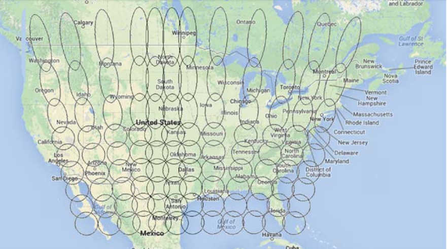
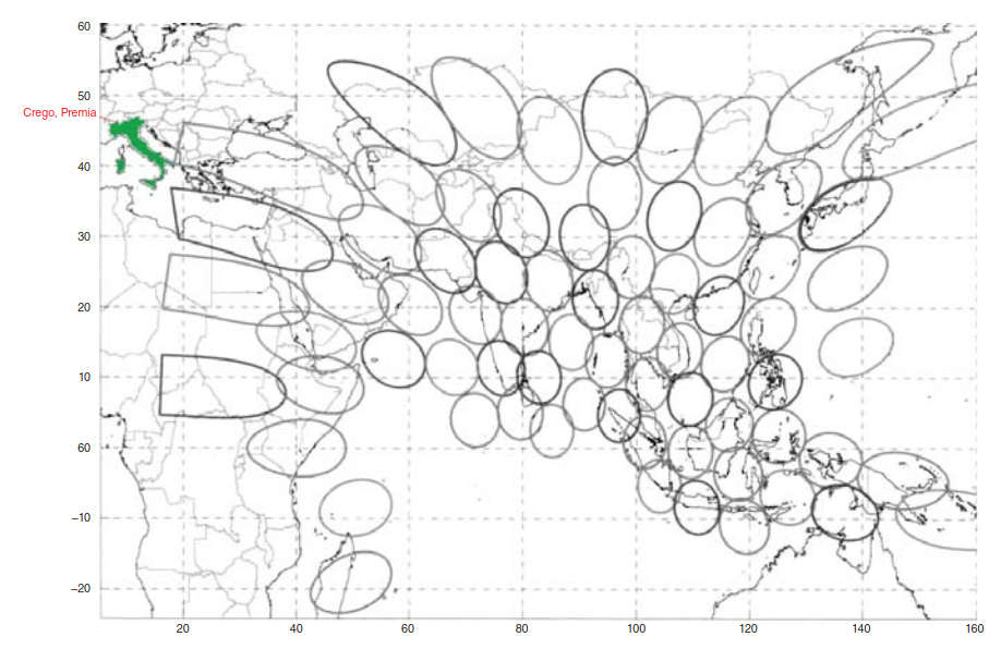
Figure 7 shows a possible example of a spot-beam coverage of the Indian and Far East region.
As mentioned, to support a (large) set of spot beams that offer a covering of a region, a number of distinct frequency subbands (“colors”) are needed. If, for example, the 500 MHz band is divided into two, there will be four colors (considering the polarizations). Figure 8 depicts an abstract spot beam system over Europe with 48 spot beams; the top shows the use of four colors, the bottom the use of three colors.
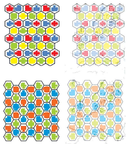
The frequency reuse factor of a multi-spot-beam antenna is the number of spots it can support divided by the number of colors; however, because of the overlap of the beams and other technical constrains the actual frequency reuse factor is usually reduced to about 50–75 % of the theoretical value. The higher the frequency reuse factor, to the degree possible, the better (note that for one zone contour beam covering, say, CONUS, the factor is 1). For example, a four-color HTS with 48 spot beams has a frequency reuse factor of 12, but because of the practical considerations just cited, the actual frequency reuse factor is 8; still, this means a multi-spot-beam satellite with 48 spots can provide about 8 times more capacity than a satellite with a large contour. A three color HTS with 48 spot beams has a frequency reuse factor of 16. This increase in satellite capacity is achieved without an increase in RF or DC power, without an increase in mass, and only minor increase in cost for the satellite.
The design desideratum for HTS tends to fall in one of the two broad categories, as hinted earlier: optimization of geographic coverage area and optimization of RF link performance. One can thus categorize the systems that have emerged of late, especially those based on the Ka-band HTS systems into two classes: those principally optimized to achieve high availability links, and those optimized mostly for large geographic coverage. The former is characterized by antennas that have beamwidths of fractional degrees; the latter relaxes link performance to use larger spot beams.
HTS spot beams typically have 3 dB beamwidths between 0,4° and 1,5°; 0,5° is typical. The developers of HTS-based services (e. g., satellite operators procuring new spacecraft from manufacturers) must balance their geographic coverage needs against the improved link performance that small spot beams can provide. For example, such a trade-off must take into account the fact that the number of transponders, the payload complexity, and the spacecraft power requirements all increase linearly with the number of beams on the satellite; hence, the reliance on very small beams also limits the available service area of the HTS. As just noted, multi-spot-beam antennas provide beams with a typical diameter of 0,4° or less; hence, a very accurate pointing of the spacecraft antenna is required. This can be achieved by the use of an active pointing system, where a beacon signal is received by a special RF sensing feed chain (one RF sensing feed chain for each reflector is required); typically, the beacon station is located inside the user geographic area. It follows that the RF sensing capability has to be provided by the feed chain on the spacecraft in addition to the Tx/Rx user and gateway function.
From a macro perspective, Figure 9 shows a conceptual view of feed horn array/reflectors on a HTS. The satellite antenna is an offset-type antenna.
For example, from a macro perspective, Figure 10 shows the utilization of dual polarization from the feed array.
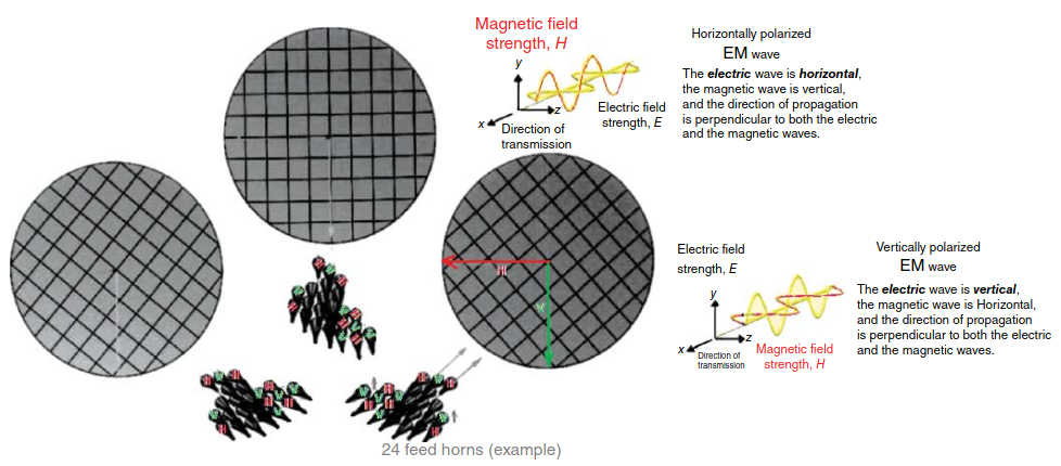
Figure 11 depicts the frequency assignments to the beams; note that if the exercise is done correctly not only will neighboring beams have different frequencies, but each spacecraft antenna will support a full complement of the frequencies (i. e., will use all of the subbands).
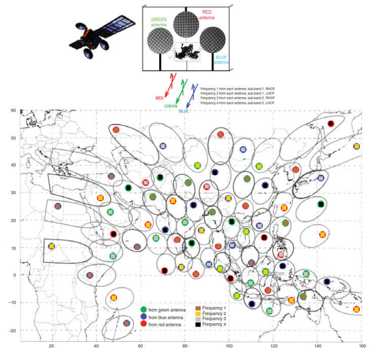
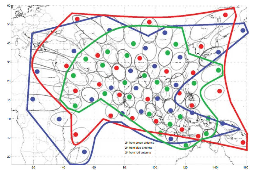
The spreading of the signals from different locations to different spacecraft antenna reduces the interbeam interference; Figure 12 shows the polygonal antenna contours for the overall operation of an antenna trio and the beam (feed) assignments on the spacecraft antenna.
Figures 13 and 14 show an end-to-end system, including the gateway function (uplink/downlink) to connect the system to the Internet (or other services).
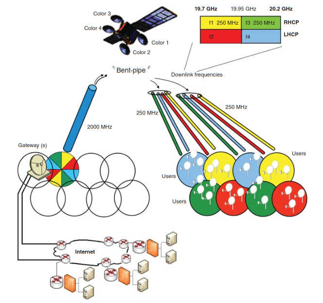
The outbound link uses TDM techniques to download information for each spot beam. The RF maximum outbound link symbol rates for third-generation HTS systems are about 45 MSps, but will increase to 250 MSps with fourth-generation HTS systems.
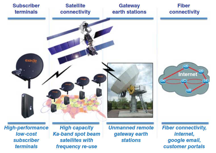
The return (inbound) channel protocols are mostly proprietary and use combinations of MF-TDMA and Aloha access protocols. The number of subscribers that can be served per beam is related to the reuse factor (between 25:1 and 50:1), the average bit rate desired per user, and the average EIRP per beam (EIRP is determined by the Traveling Wave Tube Amplifier (TWTA) size and the beams’ sizes, which determine the beam gains).
Frequency Bands of Operation
While HTSs can operate at any band and although Ku-band HTS systems are also being deployed, as noted, the Ka band is the current target of major commercialization of HTS services. There are some differences worldwide about the Ka-range frequencies, in particular, because the concept of the Ka band is not formally defined in the Radio Regulations (RR) of the International Telecommunications Union (ITU). The Ka band is generally considered to span the frequency range 17,3–31 GHz Note: in some of the bands, the concept of equivalent power flux-density (epdf) applies. The idea is to protect specified ground users (stations) from interference by certain classes of satellites: the limits define the maximum permissible interference that non-GSO FSS systems can cause to GSO FSS networks. The epfd limits were introduced by SkyBridge and adopted by the World Radio Conference 2000 (WRC-2000), and although the SkyBridge non-GSO satellite network was intended to operate in the Ku-band, WRC-2000 adopted epfd limits for portions of both the C-, Ku- and Ka-bands. At the current time there are no satellites operating using this concept. The motivation is based on desire of reusing GSO frequencies by a non-GSO constellation outside the GSO by avoiding the GSO by about ±10°. The epfd (for the uplink and for the downlink) values are calculated so that they would increase the unavailability by no more than 10 % on the most sensitive links. Therefore, in practicality, a non-GSO FSS system will cause even less than a 10 % increase in unavailability on a GSO FSS link, that is, the values are so low that they will have a negligible effect on the GSO FSS links.x.
A “preferred” range for FSS Ka applications is the 1,1 GHz band, covering the range 27,5–28,6 GHz for the uplink and 17,7–18,8 GHz for the downlink; in the United States, 28,1–28,6 GHz for the uplink and 18,3–18,8 GHz for the downlink is prevalent. Figure 15 provides a simplified view of the available Ka bands. Note that almost the entirety of Ka band is also allocated to the terrestrial Fixed Service (FS), and many countries have licensed LMDS (Local Multipoint Distribution System) services in the Ka band; specifically, in all three ITU Regions (see Exploring the Future of Satellites“Trends, Technologies and Applications of Modern Satellites”), the terrestrial FS is coprimary in most of the FSS Ka band.
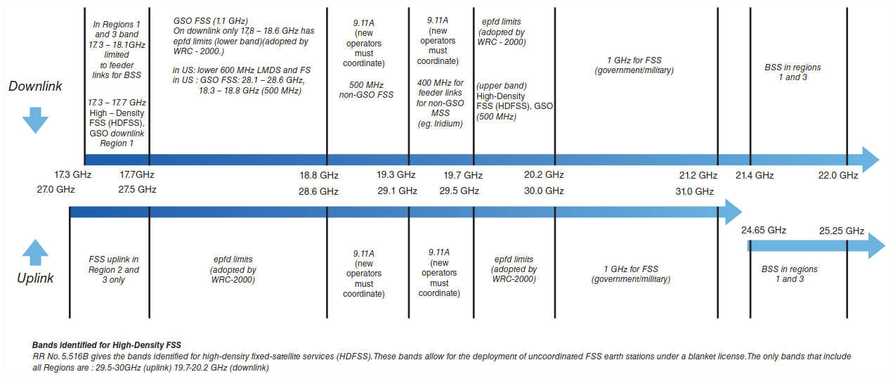
Note, incidentally, that currently there are no satellites in orbit using the new 21,4–22 GHz BSS band but satellites using this band are being planned for future DTH applications. We focus here on the main traditional Ka bands, but other bands (as per Figure 15) may be utilized in the future.
As discussed in the next section, high-frequency electromagnetic waves are fairly susceptible to rain fade: in heavy rain fall and in heavy rain fall regions, signal degradation can occur. For downlinks rain dissipates 3–10 times more energy at Ka band (20 GHz) than at Ku band (11 GHz); for uplinks rain dissipates 60–400 times more energy at Ka band (30 GHz) than at Ku band (14 GHz). To close the link and provide adequate margin at Ka, additional power is needed in the spacecraft (and/or more gain and/or higher efficiency in the antenna).
Antennas always need proper licensing. Large gateway TX/RX antennas are definitely required to comply with regulatory requirements. Smaller end-user terminals may receive blanket licensing, but the manufacturer still needs to go through technical filings and demonstrations that the equipment is generally compliant with pertinent overall regulation. For example, in the United States, the Federal Communications Commission (FCC) has approved operation of blanket-licensed remote VSAT Ku/Ka terminals in specified bands. Related to Ka, those authorizations allow the spacecraft to operate:
- In the 28,6–29,1 GHz band on a secondary basis, and;
- In the associated 18,8–19,3 GHz band on a nonconforming basis.
For example, the ViaSat-1 FCC authorization allows the spacecraft to operate:
- In the 28,6–29,1 GHz band on a secondary basis;
- In the 28,10–28,35 GHz on a secondary basis, and;
- In the 18,8–19,3 GHz band on a nonconforming basis.
Mobile antennas, say on airplanes where the movement of the aircraft may (temporarily) point/position the antenna such that it could cause interference, require more rigorous validation and associated power management mechanisms (as discussed in Aeronautical Mobility Services“Key Technologies and Innovations of Aeronautical Applications”).
In general, and in accordance with existing licensing procedures, Ka FSS operators must demonstrate that they are not creating GSO FSS interference, non-GSO FSS interference, and interference to terrestrial microwave users. These validations need to be made at a fundamental design level (is the equipment transmitting in a permitted band), as well as in consideration of other operators in the proximity (either on the ground or in space) via a frequency coordination process. Thus, Ka antenna operations (in the United States) must be compatible with the operation of adjacent GSO systems, non-GSO systems, and primary terrestrial users to use in the 18,3–19,3 GHz and 19,7–20,2 GHz downlink bands and the 28,1–29,1 GHz and 29,5–30,0 GHz uplink bands. The expectation is that the satellite network will cease operations in the 18,8–19,3 GHz downlink band (and the associated 28,6–29,1 GHz uplink band) in any spot beams, where the predicted physical alignment of such beams would fall within a specified minimum separation angle of a non-GSO operational link.
Fundamentally, in the United States, 47 CRF Section 25.132(a)(2), promulgated by the FCC, provides The full reference is as follows: Code of Federal Regulations (CRF) – Title 47 – Telecommunication – Chapter I – Federal Communications Commission – Subchapter B – Common Carrier Services – Part 25 – Satellite Communications Section 25.132 – Verification of earth station antenna performance standards. Section 25.138 Blanket Licensing provisions of GSO FSS Earth Stations in the 18,3-18,8 GHz (space-to-earth), 19,7-20,2 GHz (space-to-earth), 28,35-28,6 GHz (earth-to-space), and 29,25-30,0 GHz (earth-to-space) bands. Section 25.209 – Antenna performance standards.x that transmitting earth stations operating in the 20/30 GHz band must demonstrate compliance with Section 25.138. The antenna must meet the performance requirements in Section 25.138(a) in the direction of the GSO arc, as well as in all other directions, as illustrated by off-axis EIRP spectral density plots.
Further, as established by the FCC, the power flux density at the earth’s surface produced by emissions from a terminal must be within the -118 dBW/m2/MHz limit set forth in Section 25.138(a)(6). In addition, to the extent required for the protection of received satellite signals pursuant to Section 25.138(e), the earth station must conform to the antenna performance standards in Section 25.209, as demonstrated by the antenna gain patterns. These issues are very important in aeronautical applications, as discussed in Aeronautical Mobility Services“Key Technologies and Innovations of Aeronautical Applications”.
In closing this brief regulatory discussion, it has to be mentioned that HTS operators in the United States (and similarly in other parts of the world in accordance with local regulation), Ka FSS operators must demonstrate that they are not creating GSO FSS interference, non-GSO FSS interference, and interference to LMDS users; they must prove that they will operate in the 28,10–28,35 GHz band in a manner that will protect terrestrial microwave users, which are designated as the primary use of the band, from harmful interference.
Consistent with the secondary nature of the GSO FSS allocation in this band, the operator’s use of the 28,10–28,35 GHz frequency band for gateway earth stations must be on a nonharmful interference basis relative to LMDS. As an illustrative example, ViaSat has implemented measures to ensure that their proposed gateway/TT&C earth station will operate in a manner that will protect LMDS stations from harmful interference. ViaSat has located the gateway antenna in a remote area where LMDS is unlikely to be deployed, and it conducted a technical analysis to determine a “worst case” potential required separation distance from an LMDS terminal, assuming no shielding were employed at the gateway earth station. They determined that the required separation distance between an LMDS terminal and the gateway for the worst case alignment is 9,5 km. This is the minimum distance between an LMDS terminal and the ViaSat gateway that may require ViaSat to take measures to mitigate interference into that LMDS terminal. The actual required separation distance may be smaller depending on the characteristics of the surrounding terrain and variations in the LMDS system from the assumptions used in this analysis.
Ka-band-based technologies have matured to the point where the performance, reliability, and availability of Ka-band networks are comparable to Ku-band networks. This extends from the gateway radio frequency transmission (RFT) equipment, where the industry is bringing to market Ka-traveling wave tubes (TWTs) supporting output power up to 750 W, to the high-volume VSAT production incorporating state-of-the-art gallium arsenide (GaAs) monolithic microwave integrated circuits (MMICs) to produce reliable, cost-effective, and high-performance VSAT systems operating in Ka band. At press time, there were more than 50 active Ka-band communication projects (either in orbit or planned for launch by mid-decade); however, the majority of these satellites included (or were planning to include) Ka-band connectivity as a subset of their entire payload. HTS payloads may also include transponders for several different satellite bands: a number of satellite operators are taking the approach to incrementally add Ka-band capacity into service, while simultaneously focusing on main traditional mission on the basis of 36/54 MHz Ku- and C-band coverage optimized for TV/data broadcast (DTH or cable headends, respectively). As is typically the case for modern satellite systems, HTSs are often multipurpose designs. HTS systems may thus provide large regional and hemispherical beams as well as spot beams.
Losses and Rain Considerations
Both free space losses and rain considerations have to be taken into account in HTS designs (as is in fact the case for all satellite channels). As the transmitted signal traverses a distance of space, its power level decreases at a rate inversely proportional to the distance traveled and proportional to the wavelength of the signal. This effect is because of the spreading of the radio waves as they propagate. As radio waves propagate in free space, the power falls off as the square of range: for a doubling of range, the power reaching a receiver antenna is reduced by a factor of four.
For line-of-sight free space propagation, the loss L can be calculated by:
where:
- d – the distance between receiver and transmitter;
- λ – free space wavelength = c/f;
- c – speed of light (3 × 10⁸ m/s);
- f – frequency (Hz).
In addition to free space losses (attenuation), there are a multitude of other factors that have to be taken into account. These include, but are not limited to, attenuation, distortion, dispersion, intermodulation, fade, multipath, dropouts, and external and adjacent satellite interference, and cross-pol(arization) interference. Losses and interference degrade the reception of radio waves. Losses are typically because of absorption, for example, rain fade, among other causes. Interference can be caused, among other possibilities, by ground-based sources (e. g., terrestrial microwave links operating at the same frequency), celestial sources (sun spots), elements within the satellite system (e. g., cross-pol interference), or by transmissions by other satellite systems that use the same frequency bands. Rain impacts the performance of an RF link. Generally, the higher the frequency, the higher the attenuation caused by rain fall.
Moisture can degrade the link such that the overall signal to noise ratio drops. In heavy rain there could be portions of time when the link is unusable (outage); heavy rain can also cause depolarization, where signals from one polarization appear in the opposite polarization. The Glossary provides a longer (although not exhaustive) list of impairments and issues that have to be taken into account when designing an RF system in general and a satellite link in particular.
Electromagnetic waves are absorbed in the atmosphere; the absorption is a function of the wavelength. Oxygen (O2) and water vapor (H2O) are responsible for the majority of signal absorption. There are areas in the electromagnetic spectrum where there are local maxima; the first maximum occurs at 22 GHz because of water, and the second maximum occurs at 63 GHz because of oxygen. Note that the amount of water vapor and oxygen in the atmosphere decreases with an increase in altitude because of the decrease in pressure. Table 1 depicts the amount of rain (in mm/hr) in various rain zones – A through P – defined by the ITU Rain models are used to calculate the amount of attenuation seen by the RF link. There are a number of models available, but all models ultimately use the following equation to calculate the rain loss: A = a · Rb · L (dB) where A is the attenuation in dB, R is the rain rate seen along the susceptible portion of the RF path, and L is the length of the transmission path which is susceptible to rain. The coefficients a and b depend on RF frequency and polarization. The rain rate is a constant that depends on the site location of the RF terminal. There are a number of rain models in existence in varying degrees of revision. Practically, there are two rain models that are used extensively – the Global Crane Model and the ITU Rain Model. The models differ in the techniques and data used in calculating the various parameters in the attenuation equation. The ITU model is gaining wider acceptance of late and is updated periodically. The Global Crane model is still in widespread use but has not been updated in a number of years.x and the percentage of the time that the specified precipitation rate is exceeded.
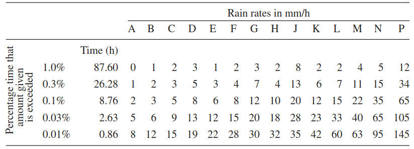
One would determine which rain zones the earth station antenna in question is located by consulting the table to determine the precipitation rate in mm/hr and the graph to determine the attenuation. When one considers designing a distribution network consisting of one hub and multiple remotes sites that are geographically distributed over the satellite downlink beam (e. g., for commercial digital video distribution), one needs to keep in mind that sites have typically a variation of the antenna type/size (impacting the gain), the noise (temperature – e. g., because of the look angle), as well as different rain fade margin requirements.
Taking into account the main contributors to attenuation, we can conclude that the (pragmatic) total attenuation through unobstructed atmosphere is the sum of free space path loss, the attenuation caused by oxygen absorption and attenuation caused by water vapor absorption, and the attenuation caused by rain when present; namely:
The issue of amplifier power both on the ground and on the satellite is important for the proper operation of a satellite link. Sufficient power is needed to be able to “close the link” (i. e., have a net power margin > 0). The transmitted power path loss for the Ku-band satellites is higher than C band, because of the higher frequency at Ku band. The path loss for a C-band signal is -196,5 dB, while path loss for a Ku-band signal is -205,8 dB. Hence, under the severe weather conditions such as heavy rain and snow, the link loss for Ku band is even higher; Ku-band systems, therefore, need more conservative rain fade margins designed into the link budget. The Ka band is impacted even more.
Some of the areas in the world where HTSs services make sense because of the dearth of infrastructure, such as tropical zones in South East Asia, Central America, and West and Central Africa, have precipitation levels of over 3 000 mm annually; thus rain fade may be an issue for Ka-band services in these locations.
Larger margins need to be included in the Ka HTS designs because of rain fade considerations, compared with C– or Ku-band operation. The Adaptive Coding and Modulation (ACM) schemes discussed in DVB-S2 Modulation Extensions and Other Advances“Exploring DVB-S2 Modulation Extensions and Advances” are applicable, in particular, for the outbound channels (to the user terminals) to minimize or eliminate the rain fade margin, which is high in the 18–20 GHz downlink Ka FSS band. ACM changes the modulation and coding rates at the gateways, on the fly (each packet), in response to the feedback on the received C/N at the user terminal (see Figure 16).
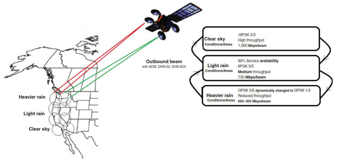
All HTSs use the DVB-S2 standard, and DVB-S2X will likely be used in the future. As we saw elsewhere in this category, ACM reduces the information rate during rain fades and resumes at the clear sky level after the rain fades (the range of C/N margin, when comparing 16 PSK clear sky to 1/2 BPSK, is approximately 12 dB).
HTS Applications
A number of applications can be supported with HTSs, as seen in Table 2. The use of HTS for mobility applications is discussed in Aeronautical Mobility Services“Key Technologies and Innovations of Aeronautical Applications”.
| Table 2. HTS Applications, Partial List | ||
|---|---|---|
| Application | Description | Considerations |
| Internet access | Provide high-speed internet access for stationary users. Evolving Ka-band multi-spot-beam HTS can provide cost-effective broadband services to areas with an underdeveloped terrestrial infrastructure. | Appropriate beam design, namely, link availability considerations. In addition, the hub must be designed to be able to manage resources (e. g., capacity) effectively during high-contention intervals to maintain class of service metrics and fair access (preventing individual subscribers to monopolize the satellite capacity). |
| Commercial VSAT networking | Provide high-quality VSAT services. | Currently, Ku-based HTS/spot beams are better suited for this application, but as described in the text, Ka approaches can also be used in moderate-rain areas. For business applications, key features will include guaranteed bandwidth throughput, latency, and jitter specifications according to a published Service Level Agreement (SLA) spec, very high network availability, support of private IP addressing, VLAN tagging, prioritization of traffic-based service classes, and support for VPNs and other forms of encryption. |
| Mobility | Provide Internet access to people on the move, either terrestrially (especially for prosumers, scientific utilizers, etc. with mobile antennas), or for aeronautical/maritime environments. | As mobile terminals move across multiple beams, there is a need for multiple “hand-offs” from beam to beam, especially in aeronautical applications. |
| 3G/4G backhauling | Provide trunking services to extend coverage to rural areas and emerging markets. | 3G and 4G cellular systems support high channel rates (e. g., 10–20 Mbps for outbound links and 5–10 Mbps for inbound links for 3G; and 100 Mbps for outbound links and 50 Mbps for inbound links with LTE), which, in turn, require higher bandwidth backhaul channels. 3G and 4G/LTE are being rolled in urban areas with terrestrial backhaul on the basis of fiber or microwave connectivity. Providing coverage in rural areas and emerging markets is challenging in general but is an emerging niche for HTS-based satellite backhaul (initially, the opportunity is more focused on 3G’s expansion to exurban areas in the developed world, but 4G services also provide an opportunity as 4G will graduate from urban areas to other less-dense markets). |
| Video distribution | DTH services in emerging countries, especially those with smaller geographies or distinct ethnic groups. | Link availability considerations. |
| M2M | Provide global coverage of M2M traffic, such as telemetry, sensor data, Internet of Things (IoT), and Unmanned Aerial Vehicles (UAVs). | The cost of the terminal devices must be kept in mind for large population wireless sensor networks (WSN) and/or IoT. Refer back to observations in Exploring the Future of Satellites“Trends, Technologies and Applications of Modern Satellites” on M2M modem costs/targets. |
Some proponents see DTH as a key driver for HTS, while others see Internet access and mobility as the major drivers (as noted in the introductory section of this article).
DTH services are currently delivered in both the BSS and FSS bands. For DTH broadcasters, the use of high-power spot beams makes it possible to achieve greater flexibility, reach, and reliability in serving consumers with relatively small antennas, to match the growth in flat-screen availability in households in parts of the world such as India, China, and Asian island nations. Small beams reusing frequencies also make it possible to provide more localized DTH services for regional linguistic markets. As discussed earlier, new Ka bands are being made available in some ITU regions, but at higher frequencies (thus with rain attenuation/higher-power implications).
WARC-1992 allocated the 21,4–22 GHz band to BSS in ITU regions 1 and 3 (Europe, Africa, Asia, and Oceania), with an effective date of April 1, 2007. The new 21,4–22 GHz BSS band will typically be used to provide a national service; however, if the service area is large enough (e. g., India, China, Russia), it could be covered with several spot beams with each spot beam catering to a specific language or cultural group. “Spot beam” DTH services that serve defined local areas are already utilized in the United States, where local broadcast services are focused on specific regions by different satellite spot beams.
SPACEWAY® 1 and -2 HTSs are being used in this way by DTH operator DirectTV; the SPACEWAY 1, -2, and -3 spacecraft were originally built to provide high-speed Internet connectivity using multiple Ka-band spot beams; however, at the time of construction there emerged a stronger-than-expected demand for DTH TV; thus, Hughes instructed Boeing to modify the SPACEWAY 1 and -2 satellites to provide simple turnaround “bent pipe” DTH broadcasts (and disable the regenerative on-board processing of the original system that was to be used for broadband satellite communications – the multiple spot beam configurations of these spacecraft meant that they could be used for local-into-local transmission; only the SPACEWAY 3 satellite has been used as originally intended).
Comparison Between Approaches
It is important to realize that satellite service providers should have a menu of offerings as one size does not fit all (as some satellite operators sometimes appear to believe). Some applications require robustness (e. g., military, real-time telemetry), while other applications (e. g., Web browsing) are more forgiving. Some applications/users place a higher priority on network reliability, user throughput, and application performance; others are looking for basic, cost-effective connectivity. These considerations may lead to different designs.
The majority of commercial communications satellite networks, including HTSs, are GSO networks. Currently, there are some industry debates about HTS in terms of the advantages/disadvantages of Ka versus Ku operation and GSO versus non-GSO. Naturally, there are vested interests of the part of the vendor community, each proposing a particular architecture. Figure 17 provides a comparison between Ku– and Ka-based operation, as well as the GSO and non-GSO systems.

In practical terms, HTS-based solutions, as an aggregate, will include a mix of frequency (and orbits), with each choice optimized for specific environments and applications. At lower frequencies (e. g., Ku band) the links require lower power/gain to overcome propagation impairments, and HTS systems have tended to use wider spot beams than is the case at the higher frequencies. Power allocation algorithms are needed for HTS operations; these schemes optimize the frequency bandwidth, the satellite transmission power, the modulation level, and the coding rate to each beam (MODCODs), to properly manage the user distributions and the interbeam interference conditions.
At this juncture it is relatively difficult to obtain commercially Ku-band orbital slots from the ITU, in particular, over industrialized regions. These orbital slots are the life blood of a satellite operator, and without additional spectrum, the growth potential of an operator is severely restricted; furthermore, many of the orbital slots are vigorously guarded by the nations over which the equatorial slots lie for national-only use Some international operators strike deals with national entities to share and/or manage an orbital slot assigned (by the ITU) to that country. Typically, said operators establish a minimalistic pied a terre in that country to meet the minimal basic letter-of-the-law regulatory requirement of the local administration.x. On the contrary, Ka-band orbital slots are generally underused: although virtually every Ka-band slot has multiple filings, only a few of the slots have actually been used, which means that it is easier for an operator to obtain rights to a Ka-band orbital slot from the ITU. Another benefit of Ka-band, as implied above, is the availability of greater amounts of spectrum compared to the Ku band. While a typical Ku-band satellite might operate across 500 MHz of spectrum, a Ka-band satellite might operate across 1 100 MHz or more of spectrum for the gateway beams.
A key disadvantage of a non-GSO HTS systems is that a constellation of (at least) eight spacecraft) are needed to provide global coverage, and all satellites in the constellation must be launched to provide continuous service (the number of spacecraft needed to provide continuous coverage depends on the altitude of the satellites – the lower the altitude the larger the number of satellites required).
Tracking antennas are needed on the ground. The fact that a constellation of satellites is needed implies that capital costs of launching a non-GSO HTS system is typically high: generally, an initial budget of around $2B is needed In the late 1990s, two non-GSO satellite networks were proposed to provide consumer Internet connectivity: Teledesic and SkyBridge. They were never launched mainly because of the initial large capital costs to implement the networks, absence of reasonably priced consumer terminals, and the difficulty of suitable installation sites as the earth station had to have a clear view of most of the sky to “see” the non-GSO satellites.x, while a GSO spacecraft in orbit may cost around $150 m range. Also, because it takes time (3–4 years or more) to build a constellation the operator’s cash flow can be challenging during that period. Furthermore, the electromagnetic environment for Low Earth Orbit (LEO) and MEO satellites is relatively harsh, so that the lifespan of an LEO satellite is typically shorter, thus requiring a more frequent replacement (the lifespan of LEOs is in the range of 7 years as compared with around 15 years for a GSO satellite). The radiation belts are two donut-shaped regions encircling the earth, where high-energy particles, mostly electrons and ions, are trapped by earth’s magnetic field. This radiation can affect the performance and reliability of satellites. The inner belt extends from about one to eight thousand miles above earth’s equator; the outer belt extends from about 12 to 25 thousand miles.
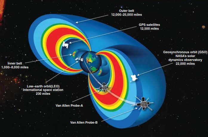
Figure 18 (from NASA) depicts the radiation regions and satellites near the region of trapped radiation.
A View of Ku-based HTS Systems
Most HTS systems deployed to date have been designed for mass markets and to operate in Ka band where small aperture antennas can provide link closure in the narrow spot beams. However, satellite operators are also now applying HTS technology and spot-beam antennas to new Ku-band spacecraft. As these HTS systems proliferate, operators of VSAT networks will have new technology choices when implementing solutions tailored to the specific application environment at hand. Mass markets are not perceived as comprising VSAT users but as individual consumers; VSAT networks, on the contrary, are typically considered to encompass an enterprise (e. g., a large national chain of stores, gas stations, or fleets).
As discussed, different applications may benefit from different HTS solutions and price points (said price points being applicable to both of the initial equipment/installation cost and the monthly recurring costs). In some instances (e. g., residential service, wireless sensor/M2M services, in-field scientific/nature research), a “best effort” Internet service may be good enough; commercial and military applications may possibly require a more robust solution. Solutions that require more robustness tend to fall in the Ku VSAT class; terminals in this class employ relatively inexpensive antennas in the 1,2–1,8–2,4 m range. Ka-band VSAT systems are currently less common, and, therefore, are more expensive than Ku-band systems of similar performance, because of lack of economies of scale in the fabrication process (Ka-based VSAT terminals in the 1,2–1,8 m range are not as of yet produced in large quantities, and, therefore, remain more expensive than Ku-band terminals). By contrast, solutions for web browsing (whether at home or on the move), especially at reasonably acceptable price points of $50–150/month, will avail themselves of the “mass market” submeter systems designed for DTH reception; these systems are generally not directly suitable for industrial-grade environments in terms of both performance and hardware reliability.
A press time, discussion centered on the use of the legacy Ku band and the evolving Ka band. The use of spot beams with frequency reuse allows both the Ku-band and Ka-band systems to achieve high overall spectrum efficiencies and HTS systems in both bands use UWB transponders. Proponents of the Ku-band approach make the case that Ka-band system may at times sacrifice link performance (e. g., availability) in favor of coverage by using larger spot beams: spot beam systems are typically limited in geographic coverage; nonetheless, some HTS systems provide large fields of spot beams that, in aggregate, create continental and even global coverage; however, others offer only a relatively small number of fixed or steerable spots in targeted areas. Ku-band spot beams and Ka-band large spots beams are similar in beamwidth and, so, are generally comparable in system coverage. Ka-band small spot beams, however, generally cover only about 10 % or 15 % of the area covered by a large spot beam.
CapRock, a purveyor of VSAT services and an advocate of Ku-based services, recently undertook a cost comparison aimed at assessing high-grade commercial/military services in the context of HTS. Figure 19 assembled from data from their study shows the relative cost of providing a constant bit rate (CBR Packet-oriented services may exhibit different economics.x) service as a function of service availability, under different climatic conditions for the three classes of HTS systems cited earlier: Ku-band spot beams, Ka-band small spot beams, and Ka-band large spot beam.
Relative performance characteristics were assessed for 1,2 m VSATs One often sees Ka-band VSATs designed with larger antennas in heavy rain regions, but that represents a drawback for many VSAT customers and if allowed could also be advantageous at Ku-band; larger VSAT antennas were not considered in the CapRock study.x located in temperate, tropical, and arid regions. The analysis isolated the effects of satellite technology and frequency band by using similar VSAT-to-satellite look-angles in the various regions, as well as common gateway locations. To the extent possible, given the different frequency bands, common earth terminal characteristics were used in the study according to the published White Paper. Furthermore, teleport locations and gateway terminal performance parameters were selected such that the VSAT-to-satellite links dominated the availability. The results shown in the figure are for the outbound (i. e., GWSV – VSAT) link, which is the most difficult to manage in these VSAT systems, because of the need to manage satellite power resources as well as satellite bandwidth. The data in Figure 19 indicate that, for the assumptions made in the study, the cost of providing a high-availability service is always lowest with a Ku-band HTS system.
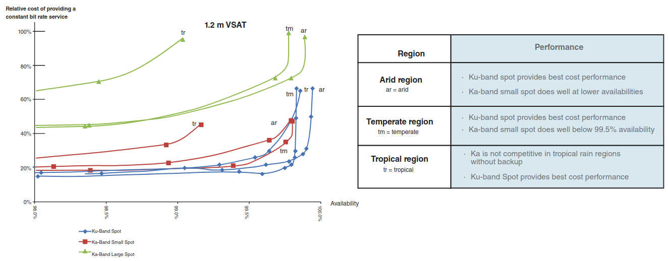
The cost difference between a small spot Ka-band HTS and a Ku-band HTS narrows as the availability of the service is reduced, and in many locations the Ka-band small spot system is at near parity with the Ku-band system for availabilities less than around 99 %. The Ku-band HTS has an advantage for customers who demand very high-service reliability. The large spot Ka-band HTS systems do not appear to be cost-competitive for providing CBR services in any of the regions considered; the costs were around 2× to 3× the costs for the other systems regardless of the service availability. As discussed earlier, Ka-band radio signals are more severely impacted by rain and other transient propagation conditions than lower frequency signals; consequently, Ka-band links require higher fade margins for a given service availability than lower frequency links, and Ka-band HTS spacecraft are designed to provide these margins. CapRock concludes that, for the assumptions made in their study, this can result in a cost penalty for the Ka-band systems when customers demand high service reliability. However, the situation can in some cases be turned to the advantage of Ka-band services, for customers whose service needs can tolerate lower availability – such as mass market or consumer clients.
Read also: Empowering Global Communication with INMARSAT Satellites in shipping
Notwithstanding the discussion above, the practicality remains that Ka-band HTSs have a clear sky advantage, which is a consequence of the fact that, intrinsically, these HTSs are designed with a large fade margin; relatively seldom, however, do the links actually require the power engineered into the link margin, especially in the North America–Atlantic–Europe zone. In other words, the propagation impairments that the link margins are designed to mitigate are reasonably rare occurrences and when not required to address transmission impairments, the power and bandwidth resources available for the link margin are exploited to operate the link at a higher data rate (e. g., with the DVB-S2X capabilities of adapting the power and/or modulation and/or forward error correction coding used on the link). Although link margins may be utilized in this manner at any frequency, the large link margins engineered by the satellite operators into Ka-based HTSs make this an intrinsic advantage for Ka-band HTSs. Downlink data rates can be increased by factors up to 10, depending on the regions and availabilities in question, and 100-fold increases in uplink data rates are also in scope.
Although the high data rates that can be achieved by adapting the link parameters in real time to exploit unused link margin are obtainable only at lower availability than the link minimum data rate, typically only a small fraction of VSATs may be operating under impaired conditions at a given time; thus, the total VSAT network throughput can be significantly enhanced by this technique. This heuristic compromise is, in particular, effective for variable bit rate (VBR) and best effort services. The technique of averaging the data rates of large quantities of VSAT sites across multiple regions, including arid climates, is used by Ka providers to calculate higher averaged network data rates. Industry analyses demonstrate that Ka-band availability in the range of 99,7 % can be achieved even in high rain fade areas (e. g., Florida in the United States, and Southeast Asia). Forward channel and return channel mitigation techniques are typically used in Ka applications (and also at C band and Ku band).
These are:
- Forward channel to the remote stations (gateway uplink):
- Adaptive coding and modulation of the forward channel (e. g., with DVB-S2X).
- Automatic level control by the spacecraft.
- Gateway radio frequency transmission diversity.
- Uplink power control at the Gateway stations.
- Use of larger antennas to achieve higher EIRP.
- Return channel from the remote stations (terminals uplink):
- Adaptive coding of the return channel (e. g., with DVB-S2X).
- Dynamic symbol shifting of the return channel.
- Uplink power control at the remote stations.
- Use of larger antennas to generate higher EIRP.
In conclusion, by availing themselves of the high rates available during clear sky conditions, Ka operators increase the overall average transmission data rates.
HTS Design Considerations
In the mid-1980s, when VSATs were being introduced to the market, the cost of a terminal was of the order of $10 000, with data throughput of 9,6–64 kbps. At press time the cost of a Ku– or Ka-band VSAT was in the hundreds-of-dollars range, with throughputs of 10–20 Mbps. The fundamental architecture of the VSAT system has not changed significantly over the years: VSAT systems typically utilize a star topology with a hub station transmitting a forward channel to the remote stations, and the remote stations make use of an FDMA/TDMA channel for the return channel; this architecture is also being employed with HTSs spot beam systems. Nonetheless, deploying HTS systems and services requires thorough knowledge of the market to be addressed.
In turn, this will drive key design factors including, although not limited to:
- The operational bands to be utilized;
- The location and size of the user beams;
- The amount of spectrum per user beam;
- The need for contiguous or noncontiguous coverage (beam hand-off requirements, in particular, for aeronautical and maritime applications);
- The location and spectrum for gateway stations.
Highly efficient gateway stations are required with HTSs. A HTS with high bandwidth spot beam channels and multiple spot beams will result in hub/gateway stations that support from 1-to-10 Gbps of capacity. A classical VSAT hub station supporting a standard transponder generally requires hub station hardware that supports in the range of 100 Mbps of capacity; typically, this VSAT system is implemented in hardware fitting one-half rack of electronics. If the operator were to use conventional VSAT hardware, the HTS gateway could require 25–50 racks of equipment, which is somewhat impractical from a space and power consumption perspective. Instead, “high-density” hardware is needed in the HTS environment. New technology has appeared on the market that is able to achieve a gateway “density” of over 1 Gbps per rack; hence, a 10 Gbps gateway can be implemented in a compact 10-rack layout, with significant efficiencies in footprint, power consumption, and environmental conditioning.
Spot Beam Antenna Design Basics (Satellite Antenna)
Earlier we mentioned two design approaches for the satellite antenna(s) used in HTS – the SFB and the MFB; in this section a more detailed view of the on-board antenna technology is provided.
Multiple beam antennas are essential enabling HTSs. Multibeam antennas operating at Ku– and Ka-band frequencies are designed to allow a single satellite to simultaneously serve hundreds of thousands of users throughout a continental region such as, although not limited to, Europe, United States, or South East Asia. Whenever a single antenna aperture is required to form a multiple set of spot-like or shaped beams, array-based solutions are used.
Options include:
- Directly radiating arrays and;
- Complex hybrid antennas composed of a number of radiating elements feeding optical systems.
With the exception of simple solutions working on a single feed per beam basis, complex BFN are often used as the illuminating assembly; the function of the BFN is to provide proper phase and amplitude excitations to the elements constituting the array.
An antenna array (also called a phased array) is a set of two or more antennas arranged in a grid. The number of antennas in an array can be as small as 2, or as large as several thousands (see Figure 20).
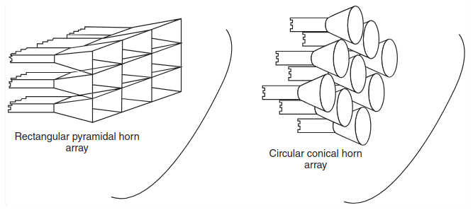
The signals from the antennas are combined and/or processed to achieve improved performance over that of a single antenna. A phased array antenna is composed of a group of individual radiators that are distributed and oriented in a linear or two-dimensional spatial configuration. The amplitude and phase excitations of each radiator can be individually controlled to form a radiated beam of any desired shape (directive pencil-beam or a fan-beam shape) in space. The position of the beam in space is controlled electronically by adjusting the phase of the excitation signals at the individual signals. Therefore, beam scanning, for example, for radar application, is achieved with the antenna aperture remaining fixed in space without the involvement of mechanical motion in the scanning process. These antennas are also used for communication applications, directing high-gain beams toward distant locations either from a ground antenna or from a satellite antenna (to define a spot beam on the ground).
The phased array can be used to:
- Increase the overall gain;
- Provide diversity reception or transmission;
- Cancel interference from a particular set of directions;
- Determine the direction of arrival of the incoming signals (e. g., for radar applications);
- “Steer” the array so that it is the most sensitive in a particular direction, and;
- To maximize the Signal to Interference Plus Noise Ratio (SINR).
Typically, the performance of an antenna array increases with the number of antennas (elements) in the array; the drawback is the increased cost, size, weight, and complexity, which is a key consideration in satellite applications. Dynamic phased array antennas tend to be expensive and are more often found in military applications.
Traditionally, most satellite antennas were not designed to cover a single point on the ground or even a regular shape, but rather to cover a certain geographically/politically dictated landmass area from the geostationary orbit. There are two techniques to design antenna that produce an irregular beam cross section (see Figure 21).
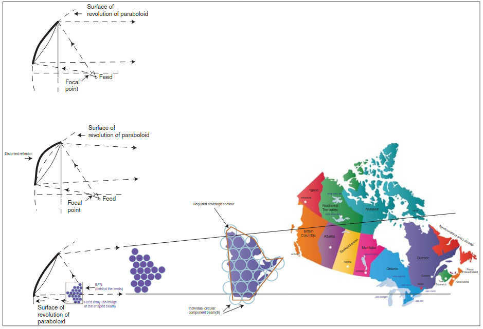
The first technique is to employ an offset reflector but to distort the reflector from the normal paraboloidal shape; the design is relatively simple, but it lacks flexibility and precision, especially for complex geographies. The second approach is to use an array of small circular component beams packed together to form the required beam shape and use the standard paraboloidal reflector. As it can be seen in Figure 21, a group of circular feed horns packed into an array, all radiating simultaneously, can form a shaped beam of any planar topological shape.
Note in Figure 21 that the antenna feed array is arranged in an inverted fashion (with respect to the desired topology on the surface of the earth) and positioned at the focal plane of the undistorted offset feed reflector. Each feed horn in the array generates one circular component beam, and the feed array is fed via a BFN. The BFN takes the signal to be transmitted and divides it in such a way that each feed horn in the array is excited by an appropriate amount of the original signal. Each individual feed horn illuminates the entire reflector, not just a portion. Because each of the feed horns in the field array forms one single-component beam in the far field, there will be a need for as many feed horns as there are component beams. The reflector and the feed horn are sized to produce the component beam efficiently.
The amount of excitation for each feed horn is adjusted in both the amplitude and the phase to maximize the power within the coverage area while at the same time minimizing the sidelobes (radiation) outside the coverage area. The beam efficiency increases as the number of component beams within a coverage area increases. However, for a specific coverage area, the size of each component beam decreases (implying, e. g., more hand-offs for a mobile user); also, the reflector size must increase as the number of feed horns increases. In turn, the BFN becomes more complex (which could add weight); finally, the focal length will increase (requiring more spacecraft structure materials and adding to the flight mechanics considerations).
The use of phased array antennas in the sky and on the ground will provide greatly increased flexibility. While this technology is not being broadly used at the current time, the expectation is that it will be incorporated in the next generation of HTSs. Initially, there will be cost hurdles, but there are operational (“run-the-engine”) cost reduction possibilities; by being able to shape coverage from the sky, one is not beholden to the antenna pattern for a given geography. For example, the US market for satellites services is seen as shrinking, but if one could reshape the beam and coverage to go where the demand is (e. g., South America) one could get to market quickly and at sunk-cost economics. On the ground one can instantly switch from one satellite to another. In addition, building electronics into the antenna will make them more efficient. Systems using metamaterials technology are being built by Kymeta as cited in Exploring the Future of Satellites“Trends, Technologies and Applications of Modern Satellites”, and the interested reader should research further. Using metamaterials has the potential to dramatically cut the costs of phased array antennas.
Single Feed per Beam Antennas
With an SFB approach, each beam is created by a single horn. To avoid gaps in the illumination of the coverage on the ground, overlapping spot beams are needed; this overlap can be achieved using a single oversize shaped reflector, or with passive and/or active lenses. A commonly used design is to create a virtual overlapping using four standard unshaped reflector antennas, one for each color; each reflector aperture creates nonoverlapping spots of a single color as depicted in Figure 22.
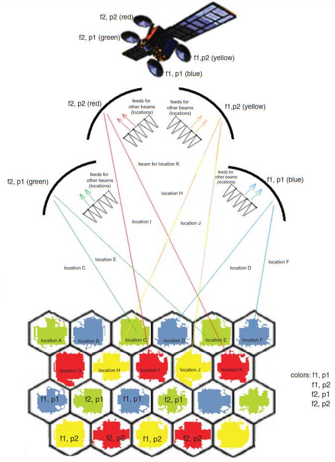
The ensemble of four antennas is oriented in such a manner that a four-color environment with overlapping spots is achieved with the four antennas. In theory, eight reflectors would be required, four for transmit (Tx) and four for receive (Rx), but one can settle with only four reflectors if complex Tx/Rx feed chains are used; specifically, because the reflector diameter is chosen for the transmit frequency, it is effectively too large for the signals at the receive frequencies (the spots would become too small and not overlap any longer); therefore, an advanced feed horn design can provide proper illumination of the reflector at Tx frequencies and a specific underillumination in the receive band frequencies.
Multiple Feeds per Beam Antennas
Figure 23 depicts a conceptual multiple feeds per beam feed system. MFB antennas create the beams using arrays of small horns; fairly sophisticated (and complicated) BFNs are needed. Adjacent beams share horns and because of this physical overlap of the feed apertures, the overlapping on-the-ground spots can be produced using only one reflector aperture. This results in a significant reduction in mass and cost and simplifies the accommodation of the antennas on the spacecraft. For larger areas, several hundreds of couplers and phase shifters have to be designed and accommodated in the different layers of the BFN. Because separate antennas for transmit and receive are used, the reflector diameter can be sized optimally for frequency and spot diameter.
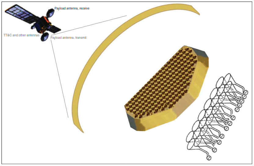
There is no single “better” choice for HTS with regard to SFB and MFB. SFB antennas have a slightly better gain performance than MFB antennas. Therefore, for mid-scope compact geographies (e.g., CONUS or Pan European applications) and large spacecraft, SFB antennas may prove to be advantageous. However, for very large geographies (e. g., Far East), the scan losses can become high; in these cases it may be advantageous to design a spacecraft for use in these orbital slot locations that replace the four SFB antennas with four MFB antennas (say two for Tx and two for Rx, where each MFB antenna provides only a half of the coverage, implying that the scan losses can be significantly be reduced; note that the cost and mass for both concepts are comparable).
As hinted above, the advantage of the MFB design is the fact that only two reflectors (one for Tx and one for Rx) are needed for a compact geography. On large spacecraft both antennas can be accommodated on the same side panel (the second side panel could be used for C– or Ku-band antennas). Smaller satellite buses are often employed, and, in general, it is difficult to accommodate four large reflectors on these buses. Industry studies show that for smaller spacecraft and for smaller geographies (e. g., Western European) MFB antennas may be the optimal choice.
Multifeed antennas can also be used for contour beams. Contour beams have a number of applications; for example, there may be a desire on the part of an operator to focus on the Caribbean area (only); or, in Europe, there may be interest in “linguistic beams” for DTH broadcast services (Figure 24 depicts a typical linguistic beam application).
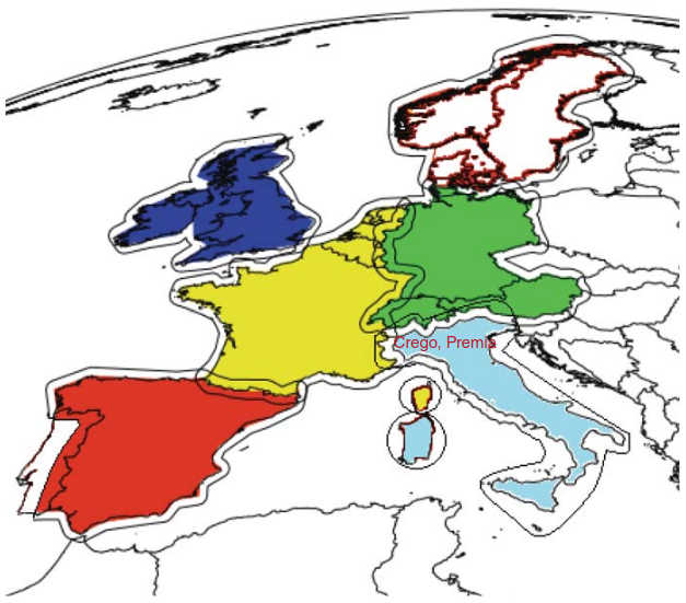
The level of frequency reuse is lower than for spot beams, but it is possible to increase the satellite capacity. A high isolation between areas with the same color is required; if the distance between contour beams using the same color is low, a large reflector is required to achieve a high isolation. An advantage of multifeed antennas is the high degree of freedom for the excitation coefficients; this makes it easier to suppress sidelobes for a high isolation between the different coverages.
Examples of HTS
This section highlights some of the key HTS systems; the list mentioned in this section is not intended to be exhaustive, but illustrative of the approach and of the early adopters. The material is based on published information by the providers, which is cited herewith to provide exposure of these providers to the reader.
While there have been notable all Ka-band launches of late, as of press time, many satellite operators were operating smaller Ka-band payloads consisting typically of 5–10 Ka-band spot beams on a satellite that also carries a C– and/or Ku-band payload; these operators may or may not want to eventually launch a full-scale, dedicated Ka-band HTS. These smaller Ka-band payloads are an effective way to test the market and to build up a client base for an eventual full-scale, dedicated HTS if the market warrants it.
The following is a list of HTS launched in recent years:
- Anik F2 (July 2004).
- Americom (SES) AMC-15/16 (October 2004).
- Thaicom 4 (August 2005).
- SPACEWAY 3 (August 2007).
- WINDS (February 2008).
- KA-SAT (December 2010).
- Yahsat Y1A (April 2011).
- ViaSat-1 (October 2011).
- Yahsat Y1B (April 2012).
- EchoStar® XVII (July 2012).
- HYLAS 2 (July 2012).
- Amazones 3 (February 2013).
- First four O3b constellation spacecraft (June 2013).
- Inmarsat-5 F1 (December 2013).
- Next eight O3b constellation spacecraft (4 in June 2014 and 4 additional planned for December 2014).
The O3b satellite constellation as well as Understanding Inmarsat SafetyNET: A Vital Tool for Maritime SafetyInmarsat’s Global Xpress constellation do not target the consumer market but they are still considered HTS.
The United States has more than 80 Ka-band geostationary orbital slots assigned to satellite operators by the FCC. Figure 25 depicts the North American Ka deployment, both for spot beams and for wideband Ka. Also, refer to Figure 3.

Globally, the overall HTS market share in 2012 was as follows:
- ViaSat (with ViaSat-1) 20 %;
- Thaicom 19 %;
- Echostar 14 % (Echostar XVII);
- Arabsat 7 %;
- Ciel 7 %;
- Eutelsat 5 %;
- Telsat 4 %;
- Others 24 %.
ViaSat and EchoStar mainly targeted at the North American broadband access market. Thaicom and Eutelsat will dominate the next tier as they build up their client bases and services on their spacecraft, respectively, Thaicom 4 and KA-SAT HTS.
ViaSat-1 and -2
With The author wishes to thank ViaSat Corporation and Mr. Bruce Rowe for this material.x a measured throughput of 134 Gbps, ViaSat-1 was the highest capacity communications satellite in the world at press time. Using a total of 72 service spot-beams (61 over the continental United States, 1 over Alaska, 1 over Hawaii, and 9 over Canada), this single satellite has more capacity than the sum of all the other FSS and BSS communications satellites (C, Ku, and Ka band) that covered North America at the time of its launch in October of 2011. This HTS technology allowed ViaSat to launch its consumer Exede® service in 2013, offering 12 Mbps downstream speed (and 3 Mbps upstream) for $50/month.
This price is comparable on a dollars/Mbps basis to most urban terrestrial systems (see Table 3).
| Table 3. Exede Services and Pricing (Illustrative) (As of Press Time) | |||
|---|---|---|---|
| Exede by ViaSat Retail Broadband Service Plans | |||
| EVOLUTION | CLASSIC 10 | CLASSIC 15 | CLASSIC 25 |
| UNLIMITED ACCESS Email & Web Pages EVEN MORE DATA: 5 GB for everything else | 10 GB each month Data Allowance for all uses | 15 GB each month Data Allowance for all uses | 25 GB each month Data Allowance for all uses |
| Early Bird Free Zone Unmetered access to everything 3 am – 8 am | Late Night Free Zone Unmetered access to everything 12 midnight – 5 am | Late Night Free Zone Unmetered access to everything 12 midnight – 5 am | Late Night Free Zone Unmetered access to everything 12 midnight – 5 am |
| ↓ 12 Mbps Download Speed | ↓ 12 Mbps Download Speed | ↓ 12 Mbps Download Speed | ↓ 12 Mbps Download Speed |
| ↑ 3 Mbps Upload Speed | ↑ 3 Mbps Upload Speed | ↑ 3 Mbps Upload Speed | ↑ 3 Mbps Upload Speed |
| $64.99/mo | $49.99/mo | $79.99/mo | $129.99/mo |
The broadband offered through ViaSat-1 is enabled through a ground system based on the ViaSat SurfBeam® 2 architecture; other innovations are as follows:
- New high-density fiber gateway servers and infrastructure and next-generation customer premises equipment capable of handling the speeds required for broadband service over ViaSat-1;
- Next generation protocol acceleration technology that minimizes the impact of latency on the user experience, including providing web browsing performance that is typically superior to 4/1 Mbps DSL-like terrestrial Internet service, and;
- Incorporation of the WiMax standard enhanced for use over satellite, combined with dynamic physical layer (dynamic modulation, forward error correction coding, and power) to more effectively combat rain fade and provide service availability comparable to that of satellite TV.
This enhanced speed, capacity, and acceleration enables subscribers to access standard web content as well as SD and HD video; any third party VoIP application or service such as Skype can be used over Exede Internet, and, in addition, ViaSat introduced its own Exede VoIP service in 2013.
ViaSat-1 has been recognized as a disruptive force in satellite broadband, earning a Guinness World Records title as the world’s highest capacity communications satellite. A February 2013 FCC report showed ViaSat’s Exede satellite Internet service was outperforming all other ISPs in the United States in delivering promised speeds to subscribers. The report revealed that 90 % of Exede subscribers were receiving 140 % or better of the advertised 12 Mbps speed during peak periods – a major shift from the previous generations of satellite Internet service, which were considered to be a “last resort” for those with no other Internet alternative.
A companion spacecraft, ViaSat-2, was near completion as of press time (to be launched mid-2016), and has the following characteristics:
- Advances broadband satellite state of the art.
- Builds on Boeing 702HP platform.
- Integrating ViaSat payload and system designs.
- Provides a ∼2x gain in bandwidth economics.
- Provides a ∼7x increase in geographic coverage.
- Provides a novel combination of:
- throughput capacity,
- geographic coverage,
- operational flexibility.
- Enables:
- Fiber To The Node (FTTN)-class consumer broadband speeds;
- Total CONUS service;
- Aero and maritime global mobile expansion;
- International expansion;
- Key operational efficiencies.
Figure 26 depicts the ViaSat-2 coverage achieved with a multitude of beams; the coverage area includes North America, Central America, the Caribbean, a small portion of northern South America as well as the aeronautical and maritime routes across the Atlantic Ocean between North America and Europe.
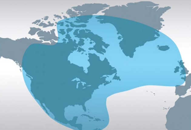
EchoStar
EchoStar XVII satellite with JUPITER™. The EchoStar XVII (EchoStar 17, also known as Jupiter 1) satellite with JUPITER high throughput technology utilizes 60 Ka spot beams, each of which is separated by a combination of frequency and polarization. EchoStar XVII is a HTS operated by Hughes Network Systems, a subsidiary of EchoStar. It is positioned for North American services in the GSO at a longitude of 107,1° W.
EchoStar XVII was built by Space Systems/Loral and is based on the LS-1300 satellite bus. Its beam layout has been combined with the earlier SPACEWAY 3 satellite to optimize coverage over North America. The Hughes SPACEWAY 3 satellite (launched in August 2007) is an early example of many of the advanced technologies used in HTS systems today, including small spot beams and frequency reuse. The SPACEWAY 3 is a Ka-band system that is able to deliver high throughput where it is needed, owing in part to the phased array antenna on the spacecraft, which enables dynamic allocation of power, as illustrated in Figure 27.
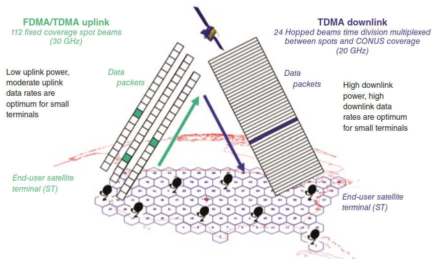
SPACEWAY 3 has the ability to support the reconfiguration of the beam sizes and shapes, and to dynamically allocate capacity per beam as the traffic needs change.
Hughes Network Systems has stated that they have achieved carrier data rates exceeding 1 Gbps on their system. JUPITER high throughput technology is the basis for HughesNet® Gen4 service introduced to the market in October of 2012. HughesNet Gen4 customers enjoy high speeds, from 10 to 15 Mbps, and a richer Internet experience, including a VoIP voice calling option. The services offered at press time are shown in Table 4 and included as an example of the typical rates and fees available with HTSs.
| Table 4. HughesNet Gen4 Service Plans | |||
|---|---|---|---|
| EchoStar XVII | Power | Power PRO | Power MAX |
| Downstream (Mbps) | 10 | 10 | 15 |
| Upstream (Mbps) | 1 | 2 | 2 |
| Anytime (GB) | 10 | 15 | 20 |
| Bonus bytes (GB) | 10 | 15 | 20 |
SES (GE Americom) AMC 15/16. SES deployed one of the first commercial Ka payloads in North America in 2004 with AMC-15 and AMC-16. The spacecraft are leased to EchoStar. SES launched these hybrid Ku/Ka FSS satellites to enter the market (but to limit the risk of an all-Ka system). AMC-15 and AMC-16 are clone satellites built by Lockheed Martin. They have 12 spot beams of 125 MHz, 10 covering CONUS, and 2 over Hawaii and Alaska. The transponders provide 3 × 40 MHz carriers per beam. The spacecraft include an IF switch to route traffic between beams/carriers. Figure 28 depicts a beam layout and a possible application.
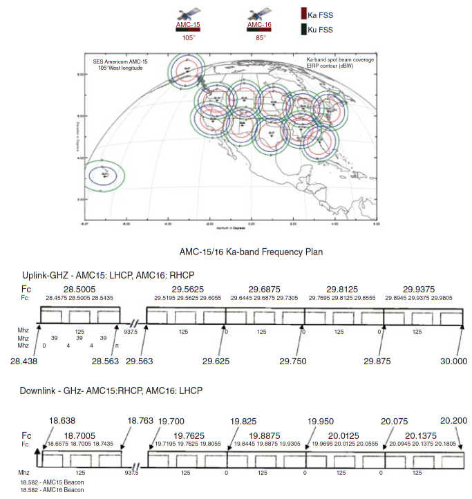
The spacecraft have been used by EchoStar Corp. In late 2014 EchoStar announced it would replace AMC-15 (also known as EchoStar 105) with a new satellite, providing EchoStar with 24 × 36 MHz Ku-band transponders; the spacecraft will be positioned at the 105 degrees West orbital position, offering coverage of the Americas, including Alaska, Hawaii, Mexico and the Caribbean. EchoStar 105 will be based on the Eurostar E3000 platform. EchoStar 105 will also be equipped with a payload of 24 C-band transponders, known as SES-11 and will be operated (“flown”) by SES.
Eutelsat KA-SAT
KA-SAT, launched This information is based on Eutelsat material.x and flown by Eutelsat, was the first all Ka-band HTS in Europe. KA-SAT has been developed to provide cost-effective broadband access and IP services. Launched end-2010 and positioned at 9° East, KA-SAT is an integral part of a network of 10 ground stations interconnected by an IP MPLS fiber network linked to four major European POPs. KA-SAT provides coverage through 82 spot beams using four different frequencies for efficient frequency reuse.
This process multiplies the available capacity by a factor of 20, to attain a broadband capacity of 90 Gbps (see Figure 29).
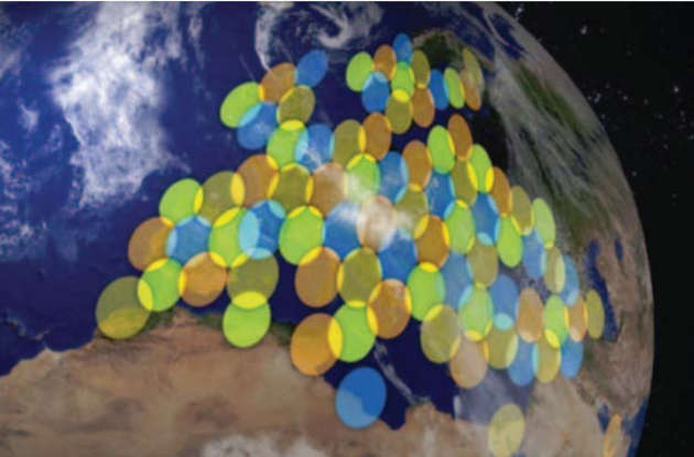
Tooway™ on KA-SAT is an advanced, high-speed Internet service via satellite for households and businesses. Tooway is available and performs equally in all KA-SAT coverage areas across Europe, the Mediterranean Basin, and some areas of the Middle East. It is also a cost-effective solution for local administrations to provide immediate access to broadband where the limited number of connections does not justify investment for terrestrial infrastructures, such as copper or fiber cables. Each Tooway-enabled home is individually equipped with a satellite kit that transmits and receives directly from the satellite. Tooway flat rate packages offer up to 18 Mbps download speeds and up to 6 Mbps upload speeds.
KA-SAT enables bandwidth-intensive, professional applications to be delivered at new, low threshold prices. Professional services on KA-SAT include broadband access and corporate network solutions for businesses, video transmission services (Satellite News Gathering – SNG) for the news and broadcasting industries, as well as data transmission for government applications. With the same advantageous bandwidth and pricing ratios, KA-SAT can also deliver carrier services, including high throughput IP trunking and mobile network backhauling. For professional services, KA-SAT provides secure broadband access of up to 50 Mbps downloads and 20 Mbps uploads to businesses in “notspots,” as well as corporate networks solutions, including network extensions, end-to-end VPN networks and backup services.
KA-SAT corporate network solutions can extend and complete existing networks, seamlessly integrating new sites to existing terrestrial intranets and carrier-supplied networks. These services are available across KA-SAT’s European-wide footprint and ground network. With NewsSpotter, the SNG service on KA-SAT, broadcasters can send SD or HD live video from the field to the studio using lightweight compact equipment and a simple automatic process of bandwidth allocation. Video and Data transmission services are also available for government applications such as emergencies, border control, e-medicine. For carrier services, KA-SAT provides competitively priced and reliable IP transport services for fixed and mobile network operators and carriers supporting, in addition to GSM backhaul connectivity to complete 2G/3G networks in underserved areas, point-to-point IP trunking and backup of network links.
Intelsat EPIC
Intelsat is planning a global service HTS system called Epic TM. The initial deployment envisioned two satellites to be deployed in different orbital locations, expected to be operational in 2015–2016; planned coverage spans nearly all global land masses. Epic is designed to provide high throughput and efficiency in an open architecture platform. Intelsat Epic is fully integrated with Intelsat’s existing infrastructure; it incorporates C, Ku, and Ka spot beams in a high-performance platform that delivers significantly more capacity and more throughput per unit of spectrum.
Epic supports:
- Fixed and wireless telecommunications operators.
- Telecommunications service providers for the oil and gas industry.
- Government and military communications.
- Private data network service providers.
- Maritime and aeronautical data service providers.
- Global organizations, including corporations and intergovernmental organizations.
- DTH and other television distribution and broadcast service providers.
- Multiple spot beam of 2-degree (or less) beam width.
- 160 Mbps spot beam capacity.
- 40 Mbps widebeam capacity.
- 25–60 Gbps of capacity.
As seen in this article, there are several HTS either in operation today or nearing deployment. While each of them has distinct features, a common design element among most of these systems (typically Ka band) is a network topology that, according to Intelsat, limits connectivity and has lower isolation of cochannel spots; as a result, most of these systems are designed with an architecture that is proprietary and closed. This topology is a limitation for many operators. Intelsat Epic allows connectivity among multiple spot beams, including star and mesh, as well as loopback within the same user beam; this guarantees backward compatibility with existing networks and forward compatibility with the flexibility to evolve the network design and technology as, and when, customers want. Intelsat Epic takes advantage of satellite antenna technology that enables multiple smaller beams to be deployed. This is similar to how consumer-focused Ka-band platforms have been deployed over small regions, but in this case the implementation is expanded to the frequency band and beam configuration that is most appropriate for each region, application, and customer set.
Intelsat Epic applies multispot technology to Ku band and C band, as well as Ka band, providing increased throughput on an efficient basis. The physics of satellite communications are well understood: for the same satellite power, the same spot beam size, and the same terminal size, all frequency bands provide the same throughput in clear sky conditions. The selection of the best frequency for a given application is, therefore, driven by many other considerations. From a satellite antenna design perspective, smaller spot sizes are easier to achieve at higher frequencies.
Some examples of the minimum size of spot-beam coverages across the different frequency bands, with a standard satellite antenna size, are:
- C band: ≈1 750 km (1 100 miles).
- Ku band: ≈1 000 km (620 miles).
- Ka band: ≈350 km (220 miles).
The wider beam width associated with C band translates to larger spot sizes; however, it is possible to generate small spots even in C band with larger satellite antennas. The use of multi-spot C band and Ku band in a bent pipe architecture will allow for an open network architecture that is backward-compatible in most instances with operators’ current network infrastructure.
The Intelsat Epic satellites will provide four to five times more bandwidth capacity than traditional satellites from frequency reuse through spot beams. In addition, because of the higher power available per spot beam and a design that minimizes RF interference between spots, the efficiency (number of bits per MHz) will be multiplied by two to three times. In total, the expected aggregate throughput on an Intelsat Epic satellite will vary according to the application served and satellite but is anticipated to be in the range of 25–60 Gbps. Whereas most HTS offer the best effort, contended service using proprietary ground equipment, Intelsat Epic offers Committed Information Rate (CIR) bandwidth using operator-selected ground platforms.
The use of spot beams on Intelsat Epic provides two additional benefits that translate into improved spectral efficiency offered to customers; that is, the Mbps that can be achieved in a MHz of satellite bandwidth (both relate to the use of smaller beam size):
- First is the increase in receiver performance (higher G/T),
- The second is the higher downlink power (EIRP) that can be provided.
The combination of increased MHz on Intelsat Epic and improved spectral efficiency enables service providers to achieve significantly higher throughputs (overall Mbps).
Global Xpress. We discuss this service in detail in Aeronautical Mobility Services“Key Technologies and Innovations of Aeronautical Applications”.
Other Traditional HTS
A short list of other HTS are as follows:
- IPSTAR (Thaicom 4) was the first commercial HTS operating in the Ku band. It is positioned at 119,5 E. It has 84 Ku-Spot Beams (2-way); 8 Ku-Spot Beams (Augment) (2-way); 3 Ku-Shaped Beams (2-way); and 7 Ku-Broadcast Beams (1-way) (see Figure 30).
- The Russian Communications Satellite Company (RSCC) had two HTS satellites at press time, as seen in Figure 31.
- The Hispasat Amazonas 3. This satellite was launched in 2013. The Amazonas 3 satellite supports the following payload: 33 Ku-band transponders; 19 C-band transponders; and 9 Ka-band spot beams. Assuming that these spot beams are 500 MHz each, this satellite will enable 9 GHz of capacity for the Ka-band data services alone.
- Hylas-1. In December 2010, the two first European Ka-band multi-spot-beam satellites, Avanti’s Hylas-1 and Eutelsat’s KA-SAT (discussed earlier) were launched. Both satellites were built by Astrium (Airbus Military, Astrium, and Cassidian are now Airbus Defense and Space) and are now fully operational in orbit. Hylas-1 is operated commercially by Avanti Communications of London and is the first satellite dedicated to delivering broadband Internet services to Europe. Its payload can be reconfigured in orbit, so that satellites can adapt to market demands, essentially future-proofing them during their typically 15-year lifetime.
- Canada’s Anik F2, in addition to C-band and Ku-band capacity, carries 45 Ka-band circular spot beams with 30 of these licensed to Wildblue Communications, and 15 dedicated to Telesat’s Canadian customers. Total throughput will range between 3 and 4 Gbs. Anik F2, a Boeing 702 spacecraft, uses a half-dozen wideband 492-MHz transponders to beam traffic to the six planned gateways, three each in the United States and Canada, relaying multiple MF-TDMA return carriers from users grouped into six to eight beams in the process. WildBlue delivers 2-way Internet satellite in the United States starting at $50/month.
O3b
O3b is a satellite constellation built with IP and mobile networks in mind. The O3B non-GSO network is planned to operate in the 28,6–29,1 GHz (uplink), 18,8–19,3 GHz (downlink); in this band, GSO and non-GSO satellite networks have equal frequency rights. The OB3 network does not suffer from the usual GSO-intrinsic latency disadvantages because of the fact that the service area, which is the area ±45° North and South latitude, can be covered continuously by a relatively small constellation of initially 8 satellites in equatorial orbit.
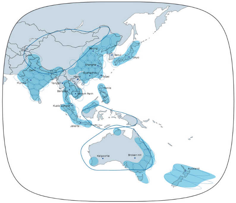
O3b’s Ka MEO constellation reduces latency and is in particular suitable for interactive applications. From any one place on earth (within the northern and southern 45-degree latitude mark) the satellites will “fly by” and provide access; but because of the fly by environment, a remote station requires a tracking antenna to track the satellite as it flies across the earth. In fact, the O3b remote stations require two tracking antennas so that the remote can perform “make-before-break” decisions and ensure that connectivity can be established with the next satellite to fly over prior to the current satellite disappearing from view (as it continues its flight around the earth).
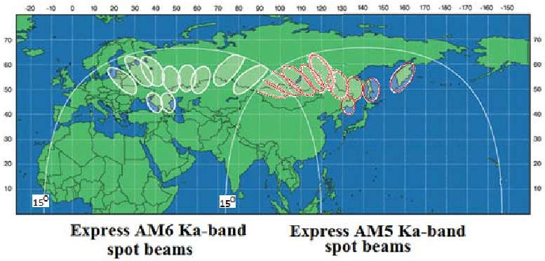
The MEO-HTS reduces delay by 75 % compared with GEO (150 ms round trip instead of 500 ms for 8 062 km instead of 36 000 km). O3b’s low latency improves the quality of voice and data service. On a per-spacecraft basis, it has a lower cost to build and launch compared with GEO.
The features are as follows:
- Each satellite has 12 steerable antennas:
- 10 antennas used for customer beams.
- 2 antennas used for Gateway connectivity.
- Each beam is independently steerable to any location within ±45 latitude.
- Beams can be stacked at the same location to provide additional capacity.
- Circular polarization is used for RHCP and LHCP.
- Each Gateway beam is connected to five customer beams:
- A single satellite supports two groups of these 1:5 configurations.
- Loopback beams can also be configured to provide localized connectivity up and down in the same beam.
- Each customer beam is configured with:
- A 216 MHz Ka-band transponder in the forward direction.
- A 216 MHz Ka-band transponder in the return direction.
See Figures 32 and 33 for beam information.
- Downlink: 17,8–18,6 GHz/18,8–19,3 GHz.
- Uplink: 27,6–28,4 GHz/28,6–29,1 GHz.
The satellites will operate in the GSO and non-GSO Ka band as follows (also see Figure 34).
The service is not intended for direct delivery to consumers but for telecom operators who can afford the more expensive tracking antennas needed; in turn, he telecom operators will resell the service to consumers using terrestrial distribution systems as WiMax or a collocated set of antennas at a cellular site (for cellular backhaul).
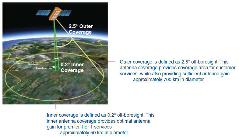
Note that the telecom operators must use two steerable antennas to track the spacecraft and retain signal connectivity by moving the path from one satellite in the constellation to another.
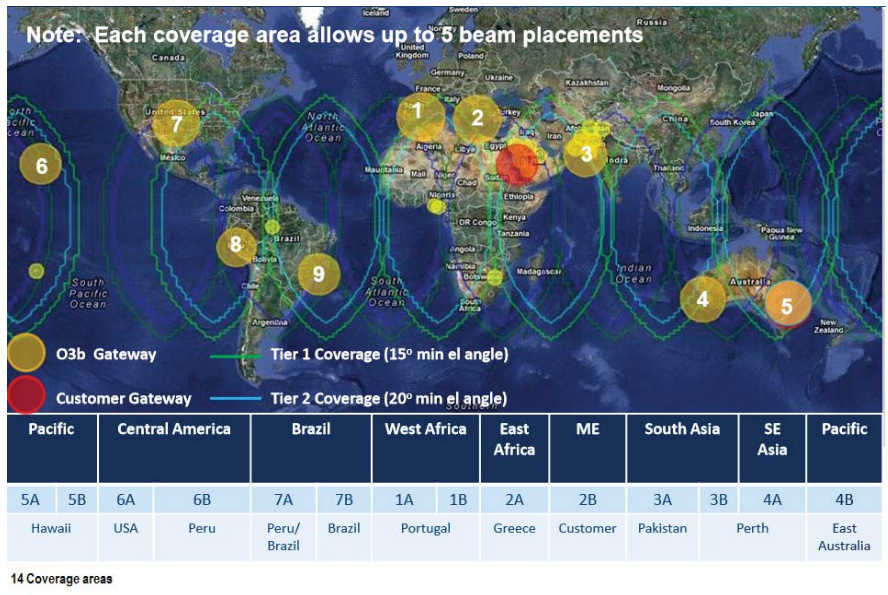
Typical PLL LNBs of the O3b antennas operate as follows:
- 17,852–18,588 GHz with a local frequency of 16,8 GHz (IF frequency on 1 052-1 788 MHz – local oscillator (LO) Stability ±1,5 ppm) (Noise temperature 101 K typical).
- 18,372–19,271 GHz with a local frequency of 17,4 GHz (IF frequency on 972–1 871 MHz – LO Stability ±1,5 ppm) (Noise temperature 101 K typical).
The BUC is typically 5 W RF (+37 dBm; 88 W input power) or 10 W RF (+40 dBm; 170 W input power) (SSPA and upconverter), to upconvert L-band IF signal to Ka-band RF signal (27,652–29,071 GHz), more specifically, operation at 27,652–28,388 GHz with 26,600 GHz LO and 28,172–29,071 GHz with 27,200 GHz LO.

The need for mechanically tracking the satellite constellation elements horizon to horizon was noted above. Mechanical systems are generally available. However, some manufacturers (e. g., Kymeta) are now developing flat panel metamaterial antennas that are capable of tracking and instantaneously switching between satellites. As of press time the vendor demonstrated both the receive and transmit capability. This antenna is currently Ka band, but the vendor was reportedly planning a Ku-band version.
Kymeta’s Metamaterials Surface Antenna Technology (MSA-T) enables wide-angle, all-electronic beam steering from a proprietary, PCB-like surface that can be manufactured using a mature and affordable lithography manufacturing infrastructure. The reconfigurability is achieved through the use of a standard PCB-like circuit board composed of several thousand subwavelength resonators that can be individually tuned. This PCB-like board is attached to a conventional feed structure. Thus, as the RF energy propagates through the system, individual tunable elements can be activated (i. e., turned “on”) to scatter a portion of this RF energy out of the guided mode. It is the pattern of activated tunable elements that determines the shape and direction of the radiated wave through the formation of a reconfigurable grating. Changing the pattern of activated elements changes the shape and direction of the beam. The net result is an antenna with the dynamic performance of a phased array but without the need for phase shifters, related amplifiers, and other components.
Wideband Global Satcom (WGS)
The Wideband Global Satcom (WGS) system is a constellation of highly capable military communications satellites that leverage cost-effective methods and technological advances in the communications satellite industry. With launches in October 2007, April 2009, December 2009, January 2012, May 2013, and August 2013, WGS Space Vehicles are the US Department of Defense’s highest capacity communications satellites. Each WGS satellite provides high-capacity service in both the X and Ka frequency bands, with the unprecedented ability to cross-band between the two frequencies on board the satellite. WGS supplements X-band communications, provided by the Defense Satellite Communications System, and augments the one-way Global Broadcast Service through new two-way Ka-band service.
Each WGS satellite is digitally channelized and transponded. These characteristics provide a an improvement leap in communications capacity, connectivity, and flexibility for US military forces and international partners while seamlessly integrating with current and future X– and Ka-band terminals. Just one WGS satellite provides more SATCOM capacity than the entire Defense Satellite Communications System constellation. International partners participating on the program are Australia, Canada, Denmark, Luxembourg, The Netherlands, and New Zealand. WGS provides worldwide flexible, high data rate, and long haul communications to soldiers, sailors, airmen, marine corps, the White House communication agency, the US State Department, international partners, and other special users.
Part of the Wideband SATCOM Division of the Space and Missile Systems Center’s MILSATCOM Directorate, the WGS system is composed of three principal segments: Space Segment (satellites), Control Segment (operators), and Terminal Segment (users). MILSATCOM is responsible for development, acquisition, fielding, and sustainment of the WGS program. Block II follow-on satellites 7, 8, 9, and 10 are anticipated for launch in FY15, FY16, FY17, and FY18, respectively. Satellites are launched either via the Delta IV or the Atlas V Evolved Expendable Launch Vehicles.
General characteristics of WGS are as follows:
- Primary Function: High-capacity military communications satellite.
- Primary Contractor: Boeing Defense, Space, and Security.
- Payload: Transponded, cross-banded-X, and Ka-band communications suite.
- Antennas: Electrically steerable, phased arrays X-band transmit and receive; mechanically steered Ka band; and fixed earth-coverage X band.
- Capability:
- WGS 1–7 39 125-MHz Channels via digital channelizer/router; 2,1 Gbps capacity.
- WGS 8–10 19 500 MHz Channels via digital channelizer/router; 2,1 Gbps capacity.

