Uncover the latest advancements in aeronautical applications in our in-depth article. Explore the mobility environment, aeronautical systems, and emerging market opportunities. Delve into technology approaches for aeronautical connectivity, including antenna technology and regulatory considerations. Learn about specific examples like ViaSat, beamforming systems, and the key players in satellite infrastructure and airline services. Stay informed on how these innovations are transforming the aviation industry.
- Overview of the Mobility Environment
- Aeronautical Systems
- Market Opportunities
- Technology Approaches to Aeronautical Connectivity
- Aeronautical Antenna Technology and Regulatory Matters
- Terminal Technology
- A Specific Example of Antenna Engineering (ViaSat)
- Beamforming and Ground-Based Beam Forming (GBBF) Systems
- Technology Players and Approaches
- Satellite Infrastructure Providers
- Vertical Service Providers to Airlines
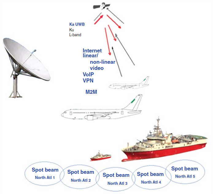
This article Services, service options, and service providers change over time (new ones are added and existing ones may drop out as time goes by); as such, any service, service option, or service provider referred to in this article is mentioned strictly as illustrative examples of possible examples of emerging technologies, trends, or approaches. As such, the mention is intended to provide pedagogical value. No recommendations are implicitly or explicitly implied by the mention of any vendor or any product (or lack thereof).x assesses emerging mobility applications and services that can be provided with satellite-based systems. Aeronautical and maritime applications are becoming important both in support of human communication (e. g., Internet access) and for machine-to-machine (M2M) communication (e. g., engine telemetry and goods tracking). Polls show that over 80 % of passengers traveling on planes now have a smartphone or laptop and would, thus, benefit from connectivity, if the service is priced reasonably. Business travelers may need to connect to their intranet, access information on the Internet, and communicate via email or Voice over Internet Protocol (VoIP) while in-flight; the casual traveler may want to connect to the Internet or access social media platforms – also there appears to be an emerging trend for the mobile consumption of entertainment streaming video. This chapter looks at satellite-based connectivity for people on the move in airplanes, in ships, and in terrestrial vehicles, but with most of the focus on aeronautical applications. In the context of airplanes, these services are being referred to as in-flight communication (IFC), which some also call in-flight connectivity. Maritime services are covered in the next article.
Overview of the Mobility Environment
Until recently, in-flight connectivity by satellite has been largely provided over traditional L-band and Ku-band, and has generally supported only low-bandwidth sessions (another common way that IFC has been supported over the years is via air-to-ground (ATG) mechanisms – but still at low bandwidth). Major airlines are now rapidly upgrading their fleets to support live in-flight entertainment (IFE) and broadband Internet connectivity, and some airlines are planning to install integrated in-flight entertainment and communications (IFECs) devices in the planes’ seatbacks. At press time major airlines were equipping their aircraft with small Ku-band tracking antennas to provide broadband Internet and live video streaming service, but Ka-based services were also emerging, as covered in High Throughput Satellites (HTS) and KA/KU Spot Beam Technologies“Applications and Design Considerations of HTS Satellites”.
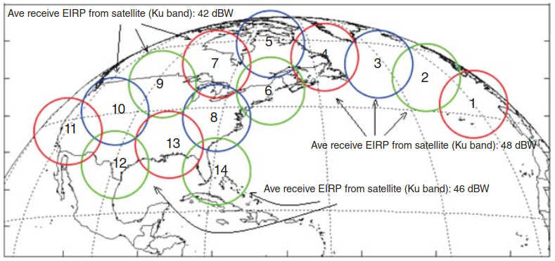
The footprint of the supporting satellite can be one large oceanic beam, or a handful of beams (e. g., an East North Atlantic–Europe – and a West North Atlantic – United States – as is the case for the SES-6 spacecraft Ku beams of the same name), or can be a tessellation of smaller Ka beams. Several satellites, each serving a portion of a route (especially a very long route), can also be used to provide broader coverage with automatic handoff between systems. Figure 1 provides a pictorial overview of the environment, while Figure 2 depicts the potential utilization of spot beams to provide such a service (e. g., over the Atlantic), which is the emerging model. Clearly, it is easier to provide services to ships because antenna size (and spacecraft tracking) is less of an issue on ships.
Proponents indicate that the Ka High-Throughput Satellite (HTS) technology is expected to fundamentally alter the economics of aeronautical broadband. Lower priced HTS capacity will animate demand in the aviation sector: the expanding service availability and the expanding geographic coverage of 3/4G HTS systems will drive the utilization of such HTS-based solutions in this vertical market.
Ka-band HTS are now beginning to be utilized for mobility services because of the following factors, among others:
- Lower per-bit cost due to improved spectrum efficiency achieved with frequency reuse and narrow spot beams, characteristic of HTS systems, as discussed in High Throughput Satellites (HTS) and KA/KU Spot Beam Technologies“Applications and Design Considerations of HTS Satellites”;
- Greater amount of spectrum available in Ka-band (up to 1,1 GHz), which results in higher channel speed as experienced by each mobile customer;
- Higher frequency and higher received power of spot beams facilitate the use of smaller plane/ship terminals, while supporting better overall performance;
- Being smaller, Ka-based terminals are simpler and quicker to install than existing Ku-band systems, minimizing downtime for aircraft and naval vessels. These terminals are more compact and lighter (this being especially important in aeronautical applications), and the terminals have a lower cost than those currently available for Ku-band.
The large majority of the airlines charge the passengers extra for in-flight connectivity services, but the business model and economics of IFC services have yet to be proven, with no clear normative model established yet. In fact, a key supplier states that:
Passenger connectivity is an on-going competitive battleground. Solutions have been around for some time, but do not yet enable a viable commercial offering on speed, coverage, and price.
The IFC market segment is very cost-sensitive; hence, the unproven willingness of passengers to pay for connectivity services limits the market growth in the immediate short term; press time estimates were that only a small minority of passengers use the service (about 5 %). Ka-based systems attempt to change these factors. In-flight phone services that became available in planes in the 1990s proved not to be economically viable because of the high prices charged and, hence, the ensuing low consumer demand The ATG telephone service was priced at around $3/min, or about 6–10X what domestic long distance service was priced at. It should be noted that home broadband costs around $2/day while some hotels charge $10–16 per night (while others give it for free), it would be interesting to see how many people personally actually sign up and pay for such a hotel service when not on a corporate trip.x. As a heuristic, one could state that since the average cost of a movie theater ticket in the United States in 2013 was around $8 for a compelling experience of 2 h of entertainment, and further state that since an Internet connection is only “half-as-compelling” as a visit to a movie theater, then the typical consumer may be willing to pay around $2/h for connectivity, or around $10–12 for a transcontinental flight; the same might apply to an easterly flight from the United States to Europe (considering that many passengers may only use the system for a couple of hours and then may want to sleep for the rest of the flight).
There are other barriers to deployment of the technology. In-flight connectivity systems represent a nontrivial investment for airlines, with Very Small Aperture Terminals (VSATs) equipment costs at approximately a-quarter-of-a-million dollars at this time and a comparable expenditure for installation. A consideration is whether the aircraft simply provides a Wi-Fi hotspot service where users utilize their own equipment, or if the goal is to provide an integrated solution also encompassing the seatback IFE, or, as yet another option, utilize tablets-handout-based IFEs. Including the cost of IFE devices, equipping a wide-body aircraft with seatback screens can cost up to $3 million; in addition, the aircraft are typically grounded for 1–3 days to install IFEC systems, impacting the aircraft’s ability to generate revenue The IFE market is a highly consolidated market. At present, the two market leaders are Panasonic Avionics and Thales, together representing more than 90 % of the IFE market. On average, the cost of equipping a single seat with traditional IFE is approximately $8 000. Handing out tablets (at $250 each) during the flight would be much less expensive, but it increases labor of distribution, collection, storage, damage, and possible theft.x.
The certification process for terminals can also be a market entry barrier: a Supplemental Type Certification (STC) is required for any IFE retrofit operation (and validations are even more intensive if Wi-Fi-based systems are being deployed), which results in a regulatory approval process that can take up to a year for each aircraft type. Fortunately for the airlines, the terminal manufacturers generally undertake the blanket product certification process, at least for the discrete subsystems.
Nonetheless, some take an altogether positive view of the market opportunities as follows:
The multitude of commercial, government and private aircraft that traverse the skies everyday represent a tremendous opportunity for broadband service providers. With the proliferation of tablets, smartphones, and other mobile devices, passengers’ desire to be online during their flight is ever increasing. Those customers demand the same quality of connection that they experience at home or in the office. High-speed IP connectivity onboard aircrafts enables a host of customer-driven applications, including in-flight consumer Wi-Fi and entertainment/video on demand services, as well as increasing operational efficiencies for the [airline] carrier.
Implementing mobile platforms using recently deployed Ka-band geosynchronous orbit (GSO) satellites is, in the view of many industry observers, the logical evolution of the deployment of mobile applications over GSO Ku-band satellites that has taken place over the past decade, also because of the advantageous overall economics. Indeed, it is now well established in the industry and in regulatory bodies [such as the Federal Communications Commission (FCC) in the United States] that use of GSO fixed satellite services (FSSs) spectrum resources for mobile platforms can be accomplished without causing incremental interference compared with what would be the case with a traditional fixed antenna. Specifically, the FCC has permitted aeronautical applications of Ku-band FSS spectrum where no service-specific rules exist, by waiving the US Table of Frequency Allocations; in addition, the International Telecommunications Union (ITU) has recognized the increased use of GSO FSS networks to provide services to earth stations mounted on mobile platforms, including the Ka-band. These arguments support the establishment of aeronautical application (or for mobile applications in general, for that matter), without being constrained to only using Mobile Satellite Services (MSSs) bands or approaches.
In fact, we noted in passing in Exploring the Future of Satellites“Trends, Technologies and Applications of Modern Satellites” that the distinction between traditional FSS and MSS is blurring. Formally “fixed” satellite services entail transmitting signals to ground antennas that remain in a fixed location, whereas “mobile” satellite services transmit signals to a moving or transportable terrestrial antenna (e. g., for shipboard services). Traditionally, MSS applications have used lower frequencies such as L-band and S-band; however, in order to support higher link capacities, MSS applications are now moving to higher frequencies, where additional spectrum bandwidth is available.
Thus, the convergence of the two, formally distinct, services is being accelerated by the availability of relatively inexpensive Ka-band capacity that can serve both communities of users. This is not a completely new development: note, for example, that WRC-03 adopted a regulation allowing earth stations onboard vessels (ESVs) to operate on a primary basis using frequencies in the FSS C-band and Ku-band; WRC-03 allowed aeronautical mobile satellite service (AMSS) applications to operate in the band 14,0–14,5 GHz on a secondary basis. These ESV and AMSS applications are implemented within frequencies assigned to FSS services, but specific technical parameters are used for the antenna platforms, to ensure that the interference levels reaching satellites in geostationary orbit never exceed the levels agreed to in the frequency coordination process. A number of national and international regulatory bodies, notably the ITU, are now proceeding with work to accommodate “formally” mobility services within the FSS in the Ka-band.
Observers state that as this convergence is being accommodated by regulators, the deployment of commercial Ka-band mobile applications becomes increasingly more economical. Based on this discussion, we use the term “mobility services” to imply satellite-oriented services directed to moving entities in the proximity of the ground (i. e., on the ground, in the air, or on the seas), regardless of the legacy terminology.
Aeronautical Systems
Traditionally, satellite terminals on aircraft have been mostly installed to support safety communication requirements, as a backup for cockpit operations; at this juncture, however, interest in satellite communication is being driven by in-flight passenger entertainment and for connectivity services (business intranet and/or Internet).
Market Opportunities
Table 1 depicts the routes with major concentration of airline traffic. Airplane-based connectivity has been provided either as ATG communication or as satellite communication; with satellite-based communications the L-band (for MSS-based solutions) or the Ku-band have been used in the recent past, but increasingly providers are shifting to HTS-based Ka solutions. HTS systems have been designed to provide as much as 100 Mbps to each aircraft in flight.
| Table 1. Routes with Major Concentration of Air Traffic | ||||
|---|---|---|---|---|
| Market ID | From | To (and Vice Versa) | Air Traffic | Average Flight Length |
| 1 | North America | North America | H | 2,5 |
| 2 | South America | M | 8 | |
| 3 | Europe | H | ||
| 4 | Europe | Europe | 2 | |
| 5 | Africa | M | 8 | |
| 6 | East Asia | H | 6 | |
| 7 | East Asia | 4 | ||
| 8 | Far East Asia | 5 | ||
| 9 | Far East Asia | 4 | ||
| 10 | Australia & Islands | M | 6 | |
| 11 | North America | M-H | 15 | |
| M = Medium; H = High | ||||
The commercial aviation market is currently supported by a number of niche service providers. These service providers, who make use of the satellite assets (usually provided by others), are clearly focusing initially on the largest markets, specifically CONUS, Transatlantic, and Europe. Key service providers at press time included Gogo®, Yonder (ViaSat), Panasonic, and AT&T.
Euroconsult, a market research firm, estimated in 2013 that approximately 12 200 commercial aircraft and approximately 16 800 business aircraft will provide in-flight connectivity services by 2022 (total 29 000); this compares with approximately 5 800 and 11 500, respectively (total 17 300), at press time (2015). Figure 3 shows that between 2015 and 2022, the total number of aircraft with IFC services will increase substantially: this represents about 11 % Compound Annual Growth Rate (CAGR) for commercial aircraft and about 5,5 % CAGR for business aircraft – about 7,5 % CAGR for the combined total.
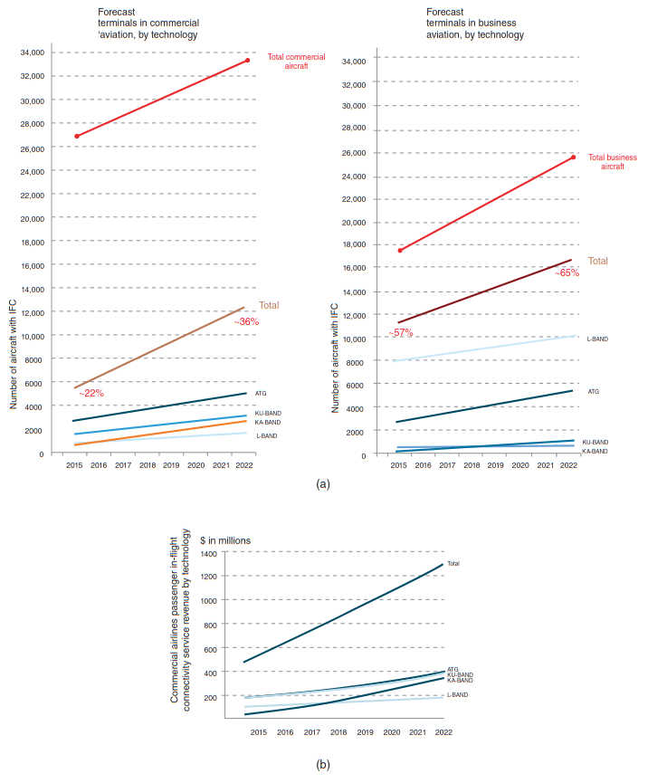
Euroconsult also forecasts that by 2022 there will be 33 700 commercial aircraft in operation, up from 23 800 in 2012, and it estimates that 25 900 business jets will be in operation by 2022, up from 17 900 in 2012. Thus, in 2015, 22 % of the commercial aircraft had IFC services; the percentage is expected to be 36 % for 2022; in 2015, 57 % of the business aircraft had IFC services; the percentage is expected to be 65 % for 2022 (in total, 37 % of all aircraft had IFC in 2015 and 49 % in 2022). Geographically, North America will dominate the market through 2022 (contributing about two-thirds the total market by various counts). Table 2 provides some summary market data from various industry sources with emphasis on VSAT/HTS aspects of the service, and Figure 3b provides a revenue forecast for the commercial airline IFC services, synthetized from data published by Euroconsult.
| Table 2. Some Market Data from Various Industry Sources | ||
|---|---|---|
| Commercial Aircrafts | Business Aircraft | |
| Ku VSAT | 1 800 aircraft (2015) → 3 100 (2022) 1,8 Gbps capacity (2015) → 11 Gbps (2022) | 1 Gbps capacity (2015) → 2 Gbps (2022) |
| Ka VSAT | ∼200 aircraft (2015) → 2,700 (2022) Negligible capacity → 20 Gbps (2022) | Negligible capacity (2015) → 5 Gbps (2022) |
| Aggregative | $400 M airline revenue (all technologies) (2015) → $1,300 M (2022) Negligible Ka revenue (2015) → $300 M (2022) $100 M sat operator revenue (2015) → $500 M (2022) Equipment revenues, tracks deployment timetables, several hundred million per year | ∼300 VSAT aircraft (2015) → 1 500 (2022) $90 M MSS revenue (2015) → $140 M (2022) $30 M FSS sat operator revenue (2015) → $100 M (2022) Equipment revenues, tracks deployment timetables |
As just noted, up to the present, a higher percentage of business aircraft compared to its total population have or have had IFC than is the case for commercial airlines; this may well follow the technology trends of the past four decades where many (telecom and computing) technologies are first enjoyed by the business community and eventually migrate to the general consumer community (notable in those categories: computers, cellular phones, and overall Internet access). The large majority of passengers now carry portable electronic devices; wireless technologies inside the cabin may be used to support IFC to these user-provided devices; otherwise, airlines may opt to funnel connectivity over their IFEC devices. At the end of 2012, 56 commercial airlines were operating connectivity services or had announced plans to offer the service, and that number has increased since then.
Technology Approaches to Aeronautical Connectivity
As noted, four different types of technology have been used in recent years to provide IFC:
- ATG;
- Satellite L-band (MSS);
- Satellite Ku-band;
- Satellite Ka-band technologies.
- ATG approaches make use of ground towers to maintain a path to the aircraft; clearly, coverage is limited to the land masses. ATG systems are less expensive than satellite-based systems and, thus, services can be provided to passengers at lower prices. Currently, ATG technology is primarily used in North America with Gogo as a key provider (China and Europe began testing ATG systems recently but deployment plans are unknown). In 2012, ATG technology was in operation on 1 800 commercial aircraft and 1 300 business jets.
- MSS-based approaches use L-band satellite technologies. MSS service providers were the first to enter the satellite-based IFC market. MSS provides global coverage. Initially, the focus was on cockpit communication services, primarily on business and military aircraft; then it expanded to passenger communication. Currently, MSS dominates the business aviation market while (the commercial aircraft market is more fragmented in terms of service options/deployments). Inmarsat and Iridium are the two satellite infrastructure providers (they also provide direct end-user services); as for key service operators, OnAir provides connectivity services to both the business and commercial aircraft market and LiveTV, with emphasis on live television, provides some services in the L-band.
- Ku-band-based approaches (Ku VSATs) represent a third wave of IFC capabilities. The services typically have regional coverage; as a consequence, there are many more satellite operators in the Ku-band market. The coverage is prevalent in the northern part of the globe, covering the North Atlantic corridor, the United States, Europe, part of Asia, and the Middle East. Two examples include ViaSat’s Yonder service with Ku-band connectivity to the business jet market on a number of satellites with a large area of coverage over the Atlantic and Pacific oceans, North America, Europe, Asia-Pacific, and the Middle East; and, Row 44 that operates over the Hughes Ku-band network and is currently focused primarily on narrow body aircraft serving the North American and European routes.
- Ka-band-based approaches (Ka VSATs) are now evolving, particularly employing HTSs (and narrow beams). As discussed in High Throughput Satellites (HTS) and KA/KU Spot Beam Technologies“Applications and Design Considerations of HTS Satellites”, Ka-band services offer higher bandwidth and smaller antennas; while the technology is more impacted by rainfade than Ku-band, this issue is of marginal interest in aeronautical applications since, in general, flights will be above the clouds. Several satellite infrastructure providers have launched or announced the launch of Ka-band satellites (as discussed in High Throughput Satellites (HTS) and KA/KU Spot Beam Technologies“Applications and Design Considerations of HTS Satellites”), notably Eutelsat with KA-SAT, ViaSat with ViaSat-1 -2, and Inmarsat with GlobalXpress (GX). ViaSat currently operates Ka-band aeronautical services in North America through its Exede in the Air service. A number of satellite operators (including ViaSat, Intelsat, Inmarsat) have designed their in-construction and/or just-launched HTS systems to support the busiest airline routes (specifically North Atlantic, CONUS, Europe).
A brief note about L-band frequencies follows next. As we saw in Exploring the Future of Satellites“Trends, Technologies and Applications of Modern Satellites”, the IEEE Standard 521–1984 positions the L-band at 1–2 GHz. This frequency range includes the Global Positioning (Service/) System (GPS) and other GNSSs (Global Navigation Satellite Systems) such as the Russian Glonass, the European Galileo, and the Chinese Beidou. It also supports SARSAT/COSPAS [Search And Rescue Satellite Aided Tracking/Cosmicheskaya Sistema Poiska Avariynyh Sudov (Space System for the Search of Vessels in Distress)] search and rescue payloads that are carried on board US and Russian meteorological satellites.
In addition, the ITU Radio Regulations allocate the band 1,452–1,492 MHz to the Fixed, Mobile, Broadcasting, and Broadcasting Satellite Service on a coprimary basis in all ITU regions with the exception of the mobile aeronautical service in Region 1; in Region 2 (the Americas), the use of the band 1 435–1 535 MHz by the aeronautical mobile service for telemetry has priority over other uses by the mobile service; in Europe, the L-band (1 452–1 492 MHz) is currently allocated for use by terrestrial and satellite digital audio broadcasting (DAB) services in most European countries, where the terrestrial segment is 1 452–1 479,5 MHz (27,5 MHz), and the satellite segment is 1 479,5–1 492 MHz (12,5 MHz).
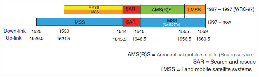
Of particular interest for the discussion in this chapter, the band also includes the MSS communication band as follows:
- 1 525–1 559 MHz (downlink) and;
- 1 626,5–1 660 5 MHz (uplink).
The Aeronautical Mobile-Satellite (Route) Service (AMS(R)S) allocation was identified since 1972 for the safety communication services. At WRC-97, the AMS(R)S allocation was made generic to MSS and a regulatory footnote was introduced to preserve priority to aeronautical safety communications (Figure 4).
As seen in Figure 3, at the current time, ATG technology has the largest deployment in commercial aircraft. This is followed by Ku-band-based systems and some L-band systems; Ka-band systems are just being introduced as discussed so far. For business jets, L-band systems had the largest deployment followed by ATG systems. By the start of the next decade, Ka-band system should rival Ku-based systems in terms of deployed terminals; Ka will experience the highest growth rates, but the other technologies (including ATG) will also see steady growth. For the business aircraft, L-band MSS and ATG will continue to grow steadily, with some deployment of Ku– and Ka-based VSATs (with about 8 000 aircraft, currently MSS represents about 70 % of the installed base; while this percentage will go down to 60 % by the beginning of the new decade – giving way to other technologies – the absolute number of aircraft with MSS systems will continue to grow to about 10 000 aircraft).
Table 3 shows a comparison between Ku-band and Ka-band approaches in terms of relative advantages and disadvantages.
| Table 3. Comparison of Technologies | ||
|---|---|---|
| Ku-Band | Ka-Band | |
| Advantages | Established technology and terminal products | Higher bandwidth |
| Currently widely deployed | Smaller antenna | |
| Lower costs of deployment | Services optimized for IP connectivity | |
| Large number of satellite operators and spacecraft | Global coverage (e. g., with Inmarsat GlobalXpress) | |
| Disadvantages | Regional coverage | Commercial unproven technology |
| Lower bandwidth | High costs of deployment | |
| More concern with creating FSS inference to other spacecraft due to large deployment of Ku | Small beam-to-beam handoff complexity | |
Table 4 depicts some of the key aeronautical initiatives pegged to airlines, as of press time.
| Table 4. Aeronautical Services on Major Airlines (examples, as of press time) (subject to change) | |||
|---|---|---|---|
| Airline | Frequency Band | Service Provider | Notes |
| Aer Lingus | HTS Ka | Live TV/Eutelsat | Wi-Fi is available on all A330 aircraft on all transatlantic routes. Pricing: Aer Lingus Wi-Fi Pass 1 h: €10,95/$14,95 Aer Lingus Wi-Fi Pass 24 h: €19,95/$24,95 |
| Air Canada | Ku | Gogo (select flights) | Gogo Inflight Internet service is available on select Air Canada flights traveling between Toronto or Montreal and Los Angeles over the United States |
| Air France-KLM | Ku | Panasonic | Trial underway in 2013. HTS Ku-band after signing a long-term agreement with Intelsat for over 1 Gbps of capacity on IS-29e and IS-33e |
| AirTran Airways | Ku | Gogo | Web, email, online shopping, and social networking on every AirTran Airways flight through the partnership with Gogo $11,00–$49,00 for computer devices $4,95–$19,95 for mobile devices |
| Alaska Airlines | Ku | Gogo (select flights) | Alaska Airlines offers Gogo Inflight Internet on almost all of their aircraft operating within the Lower 48 United States and specific areas in Alaska Gogo has flexible pricing options ranging from $1,95–$39,95 including per-flight, day passes and several different subscriptions |
| Allegiant Air | Ku | Row 44 | |
| American Airlines | Ku | Gogo (select flights) | In-flight Wi-Fi is available on American Airlines’ 767–200, selected 737–800, and selected MD-80 flights |
| Azul Brazilian Airlines | Ku | Live TV | |
| Cathay Pacific Airways | Ku | Panasonic | HTS Ku-band after signing a long-term agreement with Intelsat for over 1 Gbps of capacity on IS-29e and IS-33e |
| Delta Air Lines | Ku | Gogo (select flights) | In-flight Wi-Fi is available on Delta Airlines’ 500 aircrafts and on selected 757–200 and selected MD9-50 flights |
| El Al Israel Airlines | HTS Ka | ViaSat’s Exede in the Air/Eutelsat’s KA-SAT | Service in 2015 |
| Frontier Airlines | Ku | Gogo (select flights) | Available on ERG170 and ERJ190 flights |
| Icelandair | Ku | Row 44 | Icelandair was planning to offering Wi-Fi on its Boeing 757 flights between North America and Europe in the mid-2014, now that a deal is in place with Ku-band connectivity provider Row 44 |
| Japan Airlines | Ku | Panasonic, Gogo | A fee-based, in-flight Wi-Fi connection service that supports passengers’ own smart phones, notebook computers, and other wireless LAN devices. Upon connection through Wi-Fi, passenger will be able to enjoy reading web pages, checking your email, and updating social media networks. Available routes: Tokyo (Narita) – New York (JL005/006)/Chicago/Los Angeles/Frankfurt/Jakarta (JL725/726) and Tokyo (Haneda) – London/Paris(JL045/ 046) 1 h plan: Usage time: 1 h; usage fee: $11,95. Flight plan: usage time: 24 h; usage fee: $21,95 |
| JetBlue | HTS Ka | LiveTV/Viasat | Agreement with ViaSat (2010) to deploy the first Ka-band commercial aviation broadband network on >170 aircraft using ViaSat-1 in North America In-flight Wi-Fi is available on JetBlue’s A320 flights; free Wi-Fi-enabled devices (Wi-Fi limited to email, instant messaging, DirectTV, and shopping websites) |
| Lufthansa Airlines | Ku | Panasonic | HTS Ku-band agreement with Intelsat for over 1 Gbps of capacity on IS-29e and IS-33e |
| Mango Airlines (South Africa) | Ku | Row 44 | |
| Norwegian Air Shuttle | Ku | Row 44 | |
| SAS | Ku | Panasonic | HTS Ku-band after signing a long-term agreement with Intelsat for over 1 Gbps of capacity on IS-29e and IS-33e |
| Southwest Airlines | Ku | Row 44 | In-flight Wi-Fi via satellite |
| Turkish Airlines | Ku | Panasonic | |
| United Airlines | HTS Ka and Ku | Ka LiveTV/ViaSat’s Exede in the Air/Gogo (select flights) | United Airlines started rolling out services, with installations ramping up. ViaSat Exede In The Air service In-flight Wi-Fi is available selected 757–200 flights $11,00–$49,00 for computer devices |
| US Airways | Ku | Gogo (select flights) | In-flight Wi-Fi is available on US Airways’ selected A321 flights. Gogo $11,00–$49,00 for computer devices |
| Virgin America | Ku | Gogo | In-flight Wi-Fi is available on Virgin America’s A319 and A320 flights. Gogo $11,00–$49,00 for computer devices |
| WestJet Airlines | Ku | Live TV | |
| Business aircraft | HTS Ka and Ku | Depends on geography of operation | |
As illustrative examples of the pricing approaches, Gogo offers (as of press time) Gogo Unlimited for $59,95 per month, targeted at frequent fliers, and a Gogo All-Day Pass for $16,00 (24 h of continuous access).
Aeronautical Antenna Technology and Regulatory Matters
It has been noted by the International Telecommunications Union – Radio (ITU-R) that “GSO fixed-satellite service networks are being used at an increasing rate to provide services to earth stations mounted on mobile platforms. GSO FSS networks are currently providing valuable broadband telecommunications services to aircraft, ships, trains and other vehicles in the 14,0–14,5 GHz (earth-to-space) and in the 10,7–12,7 GHz (space-to-earth) bands, for example Resolution 902 (WRC-03). The growing demand for service to these mobile platforms has caused service providers to turn to the 17,3–30,0 GHz FSS band to meet the need for increased broadband speed, capacity, and efficiency. Advances in satellite antenna technology, particularly the development of 3-axis stabilized antennas capable of maintaining a high degree of pointing accuracy even on rapidly moving platforms, have allowed the development of mobile earth stations with very stable pointing characteristics. Similarly, the application of low power density waveforms has likewise enabled the use of smaller antennas and lower performance pointing systems while still maintaining off-axis Effective Isotropically Radiated Power (EIRP) density within prescribed limits. When properly managed and controlled, the technical characteristics of these mobile earth stations are indistinguishable from fixed earth stations when viewed from an interference perspective to FSS networks”.
There are three factors related to antenna technology in the aeronautical context:
- The need to design antennas that provide the required technical TX/RX performance (G/T, cross-pol isolation, etc.), while minimizing interference to other GSO satellites, and also being light weight and relatively inexpensive;
- The need to have the Federal Aviation Administration (FAA) (or other national regulatory entities) approve the system (for safety, aircraft interference, etc.), and;
- The fact that airlines look for a complete, integrated terminal (not just an antenna) to be installed in the aircraft.
Regulatory matters (of focus here) cover the antenna design and the frequency band of operation. Key considerations for aeronautical application do relate to the antenna construction. Most antennas currently deployed on aircrafts are a hybrid of mechanical and phased array tracking. These antennas are typically designed to meet the ITU-R requirement of generating less than 6 % increase in interference to the existing noise levels; off-axis transmit antenna gain characteristics usually do not meet ITU-R standards over the entire arc, but transmit power is lowered so that they do meet the power density in the GSO arc. Satellite service providers and terminal manufacturers also have to comply with certification procedures (e. g., with the FAA For example, an STC is required by the FAA for any IFE retrofit operation. Wi-Fi installations are subject to further assessments.x); these certifications are country dependent and product dependent, which typically entail considerable technical and financial effort (the equipment certification issue is not further discussed herewith).
As discussed in High Throughput Satellites (HTS) and KA/KU Spot Beam Technologies“Applications and Design Considerations of HTS Satellites”, for the US 47 CRF, Section 25.132 provides that transmitting earth stations operating in the 20/30 GHz band must demonstrate compliance with Section 25.138. The antenna must meet the performance requirements in Section 25.138(a) in the direction of the GSO arc as well as in all other directions, as illustrated by off-axis EIRP spectral density plots. Furthermore, as established by the FCC, the power flux density (PFD) at the earth’s surface produced by emissions from a terminal must be within the -118 dBW/m2/MHz limit set forth in Section 25.138. In addition, to the extent required for protection of received satellite signals pursuant to Section 25.138, the earth station must conform to the antenna performance standards in Section 25.209, as demonstrated by the antenna gain patterns.
Specifically in the context of Ka, aeronautical antennas must operate consistent with the existing regulatory framework for the Ka-band. Under that framework, the key element for ensuring compatibility with the FCCs 2° spacing policy (in the United States) is:
- Compliance with the off-axis-EIRP density levels specified in Section 25.138 in the uplink direction;
- Compliance with the PFD levels referenced in Section 25.138 in the downlink direction;
- In the case of any exceedance of those levels, coordination with potentially affected satellite systems.
Moreover, the longstanding, coprimary MSS allocation in the upper 500 MHz of the Ka-band (19,7–20,2 GHz, 29,5–30,0 GHz) contemplates mobile applications; thus, the FCC has acknowledged the likelihood of future licensing of mobile applications in the Ka-band once technology emerged that ensures compatibility with existing FSS applications of the Ka-band. That technology, in fact, exists today, and its efficacy has been proven over the past several years.
More specifically for (both Ku and) Ka applications, the antenna design must be such that during actual operational conditions:
- these terminals remain pointed at the intended satellite with a maximum pointing error of ±0,5° in the azimuth direction and ±1,35° in the elevation direction, and;
- the transmit output of the terminal will be inhibited in less than 100 ms should these tolerances be exceeded (whether by the motion of the aircraft or otherwise), and will not resume until the pointing of the terminal is again within these tolerances.
Within these tolerances, the off-axis EIRP density limits of Section 25.138 must be met in the GSO plane. With a good design (e.g., with a mix of quality mechanical tracking and/or phased array operation), the 3σ (σ = standard deviation) pointing error might be only ±0,27° in azimuth, and, as a practical matter, the system should never require the cessation of transmissions due to azimuth pointing errors. Elevation pointing errors should thus only cause the terminal to cease transmissions less than a fraction of 1 % of the time.
Read also: DVB-S2 Modulation Extensions and Other Advances
Pragmatically, aeronautical antenna developers may find their antennas exceed the Section 25.138 levels in certain parts of the elevation plane; perhaps, the off-axis EIRP density of the main lobe exceeds the Section 25.138(a)(2) mask in the elevation plane, and/or the off-axis EIRP density exceeds the mask at some discrete “grating” lobes in the elevation plane, far removed from the main lobe. These grating lobes could intersect the GSO arc when aircraft are operated in a limited number of geographic areas such that the antenna is oriented at a skewed angle, relative to the satellite, of approximately 25°. If these emissions cannot be rectified by technical adjustments to the antenna design, then an operator utilizing such antennas would need to coordinate the potential exceedances of the Section 25.138 off-axis EIRP density levels with all potentially affected GSO and non-geosynchronous (non-GSO) systems.
At the international level, the ITU-R document Technical and operational requirements for GSO FSS earth stations on mobile platforms in bands from 17,3 to 30,0 GHz, Rep. ITU-R S.2223, addresses FSS earth station operation on mobile platforms in the frequency range from 17,3 to 30 GHz.
The crux of the recommendations by the ITU-R regarding the matter is as follows (cited directly from the reference):
1 It is clear that implementation of FSS earth stations on mobile platforms would be simplified in bands that are not shared with terrestrial services, as this reduces the sharing situation to one of sharing between satellite networks. In such cases, in order to address potential interference with other cofrequency GSO FSS networks, it is essential that FSS earth stations on mobile platforms comply with the off-axis EIRP limits contained in Recommendation ITU-R S.524-9, or with any other limits coordinated with neighboring satellite networks. In addition, any network of such earth stations should be operated such that the aggregate off-axis EIRP levels produced in the earth-to-space direction by all cofrequency earth stations within such networks, in the direction of neighboring satellite networks, are no greater than the off-axis EIRP levels produced by other specific and/or typical FSS earth station(s) operated in conformance with Recommendation ITU-R S.524-9, or with any other limits coordinated with neighboring satellite networks. These requirements will ensure that such earth stations are essentially equivalent to stationary FSS earth stations from the perspective of static uplink interference potential.
2 Realizing that earth stations on mobile platforms operate in a dynamic environment (i. e., the position and orientation of the platform can change with time), it is important to address this aspect in specifying an essential set of technical and operational requirements. The design, coordination, and operation of earth stations on mobile platforms should be such that, in addition to the static requirements discussed earlier, the interference levels generated by such earth stations account for the following factors:
- Mispointing of the earth station antenna. Where applicable, this includes, at least, motion-induced antenna pointing errors, effects caused by bias and latency of their pointing systems, tracking error of open or closed-loop tracking systems, misalignment between transmit and receive apertures for systems that use separate apertures, and misalignment between transmit and receive feeds for systems that use combined apertures.
- Variations in the antenna pattern of the earth station antenna. Where applicable, this includes, at least, effects caused by manufacturing tolerances, aging of the antenna, and environmental effects. Networks using certain types of antennas, such as phased arrays, should account for variation in antenna pattern with scan angles (elevation and azimuth). Networks using phased arrays should also account for element phase error, amplitude error, and failure rate.
- Variations in the transmit EIRP from the earth station. Where applicable, this includes, at least, effects caused by measurement error, control error and latency for closed-loop power control systems, and motion-induced antenna pointing errors.
FSS earth stations on mobile platforms that use closed-loop tracking of the satellite signal need to employ an algorithm that is resistant to capturing and tracking adjacent satellite signals. Such earth stations must be designed and operated such that they immediately inhibit transmission when they detect that unintended satellite tracking has occurred or is about to occur. Such earth stations must also immediately inhibit transmission when their mispointing would result in off-axis EIRP levels in the direction of neighboring satellite networks above those of other specific and/or typical FSS earth stations operating in compliance with Recommendation ITU-R S.524-9 or with any other limits coordinated with neighboring satellite networks. These earth stations also need to be self-monitoring and, should a fault be detected which can cause harmful interference to FSS networks, must automatically mute any transmissions.
In addition to these autonomous capabilities, FSS earth stations on mobile platforms should be subject to the monitoring and control by a Network Control and Monitoring Center (NCMC) or equivalent facility, and these earth stations should be able to receive at least “enable transmission” and “disable transmission” commands from the NCMC. It should be possible for the NCMC to monitor the operation of the earth station to determine if it is malfunctioning.
Terminal Technology
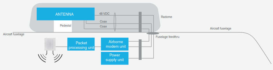
We noted earlier that airlines look for a complete, integrated terminal (not just an antenna) to be installed in the aircraft. This would include the modem and other packet processing such as:
- Transport Control Protocol (TCP) Acceleration and Hypertext Transfer Protocol (HTTP) Prefetch;
- Compression (software) modules to optimize use of bandwidth;
- Spacecraft telephony VoIP or pico-cell-based mobile phone connections support;
- Hotspot support with Quality of Service (QoS) management to/from the passenger;
- Security firewalling; and other packet classification and filtering.
Figure 5 depicts a simplified such terminal system (other systems are discussed later in the article).
A Specific Example of Antenna Engineering (ViaSat)
In this section, the various design desiderata discussed in the previous sections are pulled together using a specific example to expose the reader to the various technical aspects involved, particularly with regard to the aeronautical antenna. This section uses ViaSat Mantarry M40 antenna as an example, and it includes nearly verbatim, for useful pedagogical purposes, portions of a public 2012 domain filing to the FCC by ViaSat for such system. Beam-to-beam handoff at 500 miles can be a challenge. ViaSat systems are designed to address this requirement. The airborne terminal is an integral part of the ViaSat mobile system delivering truly broadband Internet connection speeds to passengers. The aero mobile terminal delivers typical connection speeds of 70–100 Mbps to the aircraft and 2,5–20 Mbps from the aircraft. The technical and regulatory challenges are highlighted by the discussion that follows later.
Bands of Operation. ViaSat’s proposed Ka mobile terminal operations (covered by this filing) are consistent with the Ka-band allocations in the US Table of Frequency Allocations (the “US Table”). As an initial matter, operation of the proposed mobile terminals in the 19,7–20,2 and 29,5–30,0 GHz bands is consistent with the coprimary MSS allocation in the US Table. Although there are no service rules for MSS in these bands, the requirements of Section 25.138 could be applied by analogy. By demonstrating compliance with the requirements of Section 25.138, the proposed terminals thus could be deemed compatible with adjacent Ka-band FSS satellite operations.
Moreover, as the Commission has recognized in the context of Ku-band, ViaSat’s proposed mobile operations essentially are an application of the FSS, which is allocated on a primary basis in the 18,3–19,3, 19,7–20,2z, 28,35–29,1, and 29,5–30,0 GHz bands. The mobile terminals will operate within ViaSat’s existing Ka-band FSS network. Using a highly accurate pointing mechanism, the emissions from the terminals effectively will be fixed toward the satellite points of communication and would be no more interfering than any FSS application. However, to the extent necessary, ViaSat requests a waiver of the US Table in these frequency bands to permit the proposed mobile terminals to operate as described in this application. In addition, ViaSat requests a waiver to allow these terminals to operate in the 18,8–19,3 GHz portion of the band in the absence of a GSO allocation in that band segment.
As a general matter, operation of the proposed terminals in the 18,3–19,3 and 19,7–20,2 GHz downlink bands and the 28,35–29,1 and 29,5–30,0 GHz uplink bands is compatible with the operation of GSO systems and non-GSO systems in these band segments, as well as coprimary terrestrial allocations in segments of the downlink bands. Notably, ViaSat has either coordinated the proposed antenna with, or has received confirmation that the proposed antenna can be coordinated with:
- All operating Ka-band GSO satellite networks within 6° of ViaSat-1 at 115,1° W. L. and WildBlue-1 and ANIK-F2 at 111,1° W. L.,
- All potentially affected Ka-band GSO satellite networks outside of the 6° range, and;
- The one potentially affected Ka-band non-GSO network.
ViaSat has completed coordination with O3b, which is the only relevant commercial non-GSO system in the 18,8–19,3 and 28,6–29,1 GHz band segments.
GSO FSS Operations Section 25.132(a)(2) provides that transmitting earth stations operating in the 20/30 GHz band must demonstrate compliance with Section 25.138.15. While there are no rules for mobile operations in the Ka-band, operating the proposed terminals consistent with the technical parameters of Section 25.138 would ensure compatibility with satellite systems operating in the Ka-band. This approach is consistent with the ITU’s recommendation in Report ITU-R S.2223 that GSO FSS earth stations on mobile platforms in bands from 17,3 to 30,0 GHz comply with the off-axis EIRP limits coordinated with neighboring satellite networks.
The FCC has acknowledged the potential for MSSs in the Ka-band to be able to coexist with FSS. When the Commission designated the 19,7–20,2 and 29,5–30,0 GHz bands for GSO FSS, it maintained the MSS coprimary allocation in the US Table of Frequency Allocations because it believed “that the development of technology may enable these two different types of systems to coexist in the same frequencies in the future.” As in the case of the Ku-band, mobile systems can operate on FSS platforms in the Ka-band without causing harmful interference to FSS operations. Moreover, as discussed earlier, ViaSat has coordinated the proposed antenna, or will soon complete such coordination, with all potentially impacted satellite operators. The FCC has found coordination to be adequate in the context of Ku-band mobile aeronautical operations, and that such satellite operators are capable of assessing the potential interference impact of such mobile operations.
Thus, the proposed terminal operations are compatible with and will not cause harmful interference into FSS systems. As described later, the proposed antenna complies with the Section 25.138 EIRP spectral density limits in the GSO plane. Furthermore, the antenna control unit (ACU) and closed-loop tracking system allow the terminal to be pointed accurately at the satellite while in motion, thereby protecting adjacent satellite operations.
Namely, ViaSat will ensure that:
- These terminals remain pointed at the intended satellite with a maximum pointing error of ±0,5° in the azimuth direction and ±1,35° in the elevation direction, and;
- The transmit output of the terminal will be inhibited in less than 100 ms should these tolerances be exceeded (whether by the motion of the aircraft or otherwise), and will not resume until the pointing of the terminal is again within these tolerances.
Within these tolerances, the off-axis EIRP density limits of Section 25.138 will be met in the GSO plane. Notably, because the 3σ pointing error is only ±0,27° in azimuth, as a practical matter, the system should never require the cessation of transmissions due to azimuth pointing errors. Elevation pointing errors should only cause the terminal to cease transmissions less than 0,27 % of the time.
The antenna does not comply with the Section 25.138(a)(2) EIRP spectral density limits in certain areas of the elevation plane. However, ViaSat satisfies the requirements of Section 25.138(b) to ensure that adjacent GSO systems are adequately protected from any higher power operations. The antenna pattern shows off-axis exceedances for the main lobe and four grating lobes along the elevation axis and well outside of the GSO. GSO FSS networks will never be impacted by the exceedance of the main lobe along the elevation axis, and the grating lobes would intersect the GSO arc only when the aircraft is traveling within certain geographic locations in which the GSO arc appears skewed with respect to the local horizon of the antenna, or when the aircraft is banking at certain angles while in flight. Due to the high speeds at which aircraft travel, any intersection of a grating lobe with the GSO arc likely would be fleeting. Moreover, due to the large off-axis angles where these grating lobes occur, the actual level of interference to any GSO satellite is well below the 6 % delta T/T threshold that triggers satellite coordination.
Non-GSO FSS Operations in the 18,8–19,3 and 28,6–29,1 GHz bands need to be addressed. Pursuant to the terms of the Commission’s authorization of ViaSat-1, operation of the GSO FSS system in the 28,6–29,1 GHz band is on a secondary allocation, and in the 18,8–19,3 GHz band is on a non-conforming basis. The Commission has approved operation of the ViaSat-1 satellite in these bands, and has acknowledged that ViaSat can operate in these bands while protecting the primary non-GSO FSS operations. The same previously approved capability of ViaSat-1 to cease operations in these bands in the event of an inline event between ViaSat’s communications and the non-GSO system’s communications will also avoid interference from communications with proposed terminals into non-GSO systems. Each of the proposed terminals will be dynamically controlled and can shut down operations in the bands in which non-GSO systems have priority when a non-GSO satellite is within the minimum line-of-sight separation angle established through coordination.
As summarized earlier, while the sidelobes of the proposed antenna exceed the Section 25.138(a)(2) limits in the elevation plane at the main lobe and at the four discrete points identified, ViaSat has coordinated the operation of the proposed antenna with O3b, which currently is the only potentially impacted non-GSO FSS system. ViaSat will coordinate its aeronautical terminal operations with any future potentially affected non-GSO applicants.
Terrestrial coordination also needs to be addressed. When the FCC adopted allocations for the Ka-band, it established sunset provisions for the coprimary status of certain terrestrial users in the FSS downlink bands in order to protect and facilitate deployment of FSS operations. Terrestrial microwave users maintain coprimary status in the 18,3–18,58 GHz band until November 18, 2012. In accordance with the blanket licensing rules, no coordination with terrestrial or other users is required on the GSO frequencies.
The mobile nature of the proposed terminals does not change the satellite downlinks from ViaSat-1, WildBlue-1, and ANIK-F2. The PFD at the earth’s surface produced by emissions from each of the satellite points of communication are within the -118 dBW/m2/MHz limit set forth in Section 25.138(a)(6). Therefore, the RF environment in which the grandfathered terrestrial users operate will not change as a result of the proposed terminal operations. Moreover, ViaSat may either accept any potential for interference from the coprimary terrestrial users until the sunset date or relocate such users. ViaSat will accept the potential for interference from such users until the relevant sunset date.
Regarding blanket licensing of Ka terminals, because ViaSat’s proposed operations are consistent with the policies underlying Section 25.138, which establishes the requirements for routine processing of blanket-licensed Ka-band terminals, a waiver of Section 25.138 is unnecessary for blanket licensing of the proposed terminals. Moreover, blanket licensing as proposed here is fully consistent with the FCC’s precedent. The Commission has implemented blanket licensing procedures on a case-by-case basis (and in the absence of service rules) where circumstances have warranted such an approach. The Commission’s policy justifications underlying its adoption of blanket earth station licensing procedures in rulemaking proceedings and declaratory rulings are equally applicable to the subject application. Allowing processing flexibility in this case will promote the expanded use of spectrum and the rapid development and deployment of new technologies. Such an approach serves the public interest by reducing administrative costs and delays and by accelerating system deployment, which facilitates the delivery of service to end-users. Blanket licensing of the proposed terminals will speed the delivery of mobile broadband services to consumers on commercial aircraft. Therefore, flexibility in processing this application is warranted and is consistent with recent precedent.
Network. The proposed Ka terminals will operate in the same SurfBeam 2 Ka-band network as residential customers using the fixed VSAT equipment. Building upon its experience with Ku-band-based AMSS and ESV mobile broadband, ViaSat has incorporated the functions necessary to support mobility into the management functions of the SurfBeam 2 network. The network allows the aircraft to fly across the service area and seamlessly switch from spot beam to spot beam within the current operational satellite and to switch between satellites as coverage dictates.
Generally, when within the coverage footprint of ViaSat-1, the terminals will operate using ViaSat-1 spot beams to take advantage of its higher power and G/T and thereby enjoy improved throughput. As the aircraft flies across areas not supported by ViaSat-1, the AES will switch to capacity on the WildBlue-1 or Anik-F2 spacecraft.
The link budgets in Table 5 are included to illustrate typical links on each of the satellites. Because the SurfBeam 2 architecture employs adaptive coding and modulation, the terminals could transmit at any code and modulation point within the library of available choices. The available symbol rates are 625 000 symbols per second, or kilobaud (kBd), 1,25, 2,5, 5, and 10 MBd. Service traffic typically uses the 1,25 MBd or higher symbol rates. While the service may be operational when the aircraft is on the ground, in general operation will be while the aircraft is in flight and above most rain attenuation. The link budgets in Table 5 demonstrate that no margin shortfalls are present for clear sky operation (margins in the 0,7–2,4 dB range).
| Table 5. Link Budgets | |||||
|---|---|---|---|---|---|
| Forward Link Budgets | |||||
| General | Units | ViaSat-1 | WB-1 22 MBd | AF-2 22 MBd | |
| Symbol rate | MBd | 416,7 | 22,0 | 22,0 | |
| Data rate | Mbps | 550,9 | 43,6 | ||
| Modulation and coding rate | QPSK, r=2/3 | 8PSK, r=2/3 | |||
| Carrier bandwidth | MHz | 500,0 | 26,4 | ||
| Uplink frequency | GHz | 28,60 | 29,75 | ||
| Download frequency | 18,80 | 19,95 | |||
| Uplink | Tx E/S EIRP per carrier | dBW | 65,2 | 74,0 | 68,0 |
| Atmospheric and rain losses | dB | 0,50 | |||
| Free space loss | 213,3 | 214,0 | |||
| G/T toward Tx E/S | db/K | 24,2 | 13,0 | 15,0 | |
| C/1 – intra system | dB | 22,9 | 19,2 | 19,1 | |
| Downlink | EIRP per carrier toward Rx E/S | dBW | 60,7 | 53,6 | 52,0 |
| Rx E/S pointing loss | dB | 0,3 | 0,5 | ||
| Atmospheric and rain losses | 0,5 | ||||
| Free space loss | 209,3 | 209,8 | |||
| Rx E/S G/T incl. radome | dB/K | 12,0 | 12,5 | ||
| C/1 – intra system | dB | 16,0 | 15,9 | 17,9 | |
| End-to-End | C/N – thermal uplink | dB | 18,0 | 28,4 | 23,7 |
| C/1 Up – ASI | 29,1 | 43,4 | 38,7 | ||
| C/N – thermal downlink | 5,0 | 10,5 | 8,9 | ||
| C/1 Down – ASI | 20,8 | 32,5 | 30,9 | ||
| C/(N+1) – total actual | 4,3 | 8,9 | 7,8 | ||
| C/N – required | 3,6 | 7,2 | |||
| Excess margin | 0,7 | 1,7 | 0,6 | ||
| Return Link Budgets | |||||
| General | Units | VS-1 10 MBd beam interior | WB-1 5 Msps beam interior | AF2 5 MBd beam interior | |
| Satellite location | °E | -115,1 | -111,1 | ||
| Symbol rate | MBd | 10,00 | 5,00 | ||
| Date rate | Mbps | 12,50 | 5,00 | ||
| Modulation/coding rate | QPSK, r=5/8 | QPSK, r=1/2 | |||
| Carrier bandwidth | MHz | 12,5 | 6,25 | ||
| Uplink frequency | GHz | 28,60 | 29,75 | ||
| Downlink frequency | 18,80 | 19,95 | |||
| Uplink | Tx ES EIRP per carrier | dBW | 44,8 | 43,7 | |
| Radome Loss | dB | 1,2 | |||
| Tx E/S EIRP density | dBW/40 kHz | 19,6 | 23,9 | ||
| Tx E/S ant pointing loss | dB | 0,7 | |||
| Atmospheric/rain loss | 0,5 | ||||
| Free space loss | 212,9 | 213,3 | |||
| G/T toward Tx E/S | dbK | 22,7 | 16,0 | ||
| C/1 – intra system | dB | 18,2 | 15,5 | 17,5 | |
| Downlink | EIRP/cxr toward Rx E/S | dBW | 39,2 | 35,1 | 35,9 |
| Atmoshperic/rain loss | dB | 0,5 | |||
| Free space loss | 209,4 | 209,3 | 209,2 | ||
| Rx E/S antenna diameter | m | 7,3 | 8,1 | ||
| Rx E/S G/T | dB/K | 37,4 | 39,0 | 38,3 | |
| C/1 – intra system | dB | 15,0 | 16,4 | 15,1 | |
| End-to-End | C/N – Thermal uplink | 9,7 | 8,0 | ||
| C/1 Up – ASI | 11,8 | 9,8 | 10,3 | ||
| C/N – Thermal downlink | 25,3 | 25,9 | 26,2 | ||
| C/1 Down – ASI | 35,4 | 22,6 | 21,2 | ||
| C/(N+1) – Total actual | 6,5 | 4,9 | 5,1 | ||
| C/N – Required excess margin | 2,3 | 2,4 | |||
The SurfBeam 2 architecture is designed to always operate at the lowest power density modulation and code point that allows the link to close. The network employs active power control and reduces power when conditions permit, keeping the Es/No margin at 1 dB or less. When the modem has sufficient excess transmit capability, it will automatically switch to the next symbol rate and increase data rate, keeping the EIRP density at the minimum. This further reduces the likelihood that the system will impact traffic on other satellites.
Antenna and Pointing Accuracy. The antenna used in this application is a low profile waveguide horn array. The Mantarry M40 is a mechanically steered waveguide horn array antenna. The M40 designation reflects the number of feed horns across the width of the aperture. The M40 shown in Figure 6 is 40 horns wide with several horns at the upper corners of the array deleted to provide radome clearance. The height of the array is 15,75 cm and the width is 78,75 cm.

These antennas have two transmit receive interface adapters (TRIAs), one for each polarization. The TRIAs are similar in design to the outdoor units used on ViaSat’s current blanket licensed earth station, but modified for airborne use and with slightly higher output power. The TRIA feeds a passive feed network which divides and routes the power to each of the feed horns in the array.
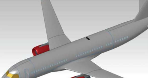
The Mantarry antenna will be fuselage-mounted typically as depicted in Figure 7 and will be covered by a radome (the same radome may also house a receive-only antenna for DBS satellite TV services; the DBS satellite receive-only antenna and service are not associated with, or part of, the IFC application under discussion).
The terminal is directed toward the intended satellite by the ACU, which receives input data from the inertial reference unit (IRU) that is part of the avionics navigation system of the aircraft. This input includes information, such as the current latitude, longitude, altitude, pitch, roll, and yaw. The ACU uses this information to calculate the initial pointing angles and polarization for the antenna to the desired satellite (ViaSat-1, WildBlue-1, or Anik-F2). Once the required pointing angles have been determined, the ACU will drive the antenna to the desired position and the modem will attempt to acquire the receive signal from the satellite. When the signal is received and the modem is able to properly identify and demodulate the carrier, the antenna will enter a closed-loop tracking mode.
By performing closed-loop tracking, the ACU is able to properly account for any installation alignment differences between the IRU/airframe and antenna, as well as bending of the aircraft body on the ground or in flight. The antenna system also incorporates local rate gyros to mitigate latency between the IRU and the Mantarry ACU and further improve pointing accuracy.
The mean pointing error is 0° in both the azimuth and elevation directions, and the standard deviation (σ) for each axis is given in Table 6 along with the peak pointing error (3σ or 99,73 %). The pointing error values are different in the azimuth and elevation directions because the arrays are wider than they are tall.
| Table 6. Pointing Error | ||||||
|---|---|---|---|---|---|---|
| 1σ Azimuth | Elevation | 3σ Azimuth | Elevation | Limit Azimuth | Elevation | |
| M40 | ±0,09° | ±0,45° | ±0,27° | ±1,35° | ±0,5° | ±1,35° |
The M40 has a 5:1 width-to-height aspect ratio, and accordingly the elevation beamwidth is wider than the azimuth beamwidth by the same factor. Likewise, the target standard deviation for pointing accuracy follows the same ratio.
The ACU monitors the current and target pointing directions, and if the error limit in either the azimuth or elevation axis is exceeded, the transmit output from the modem is inhibited in less than 100 ms (20 ms typical). The pointing error threshold is programmable for each axis, and ViaSat proposes to inhibit transmissions should the pointing error exceed 0,5° in the azimuth direction, or 1,35° in the elevation direction. As noted earlier, because the 3σ pointing error is only ±0,27° in azimuth, the system should not inhibit due to azimuth pointing errors. Elevation pointing error should only cause the antenna to inhibit transmit less than 0,27 % of the time (Table 6).
Antenna Patterns. The antenna patterns generated by the M40 antenna differ from those typically encountered when considering circular or mildly elliptical reflector type antennas. The patterns are characterized by a narrow main beam and a line of sidelobes in the azimuth axis, a wide main beam, and line of sidelobes in the elevation axis, and relatively low-amplitude sidelobes elsewhere. Figure 8 depicts an X–Y view of the azimuth and elevation patterns when looking directly into the boresight of the antenna. The figure illustrates the lobes that exceed the Section 25.138 limit.
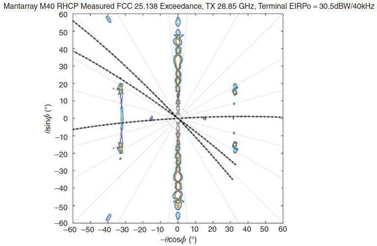
Notably, there are four grating lobes in the transmit antenna patterns that are well removed from the main lobe. These grating lobes are only present for a limited range of skew angles centered around approximately 25° of skew. The location and amplitude of the grating lobes are a function of transmit frequency and typically are between 25° and 35° off-axis from the main lobe. While the amplitude of these grating lobes when operating at the highest clear sky EIRP is as much as 22 dB above the 25.138 off-axis EIRP density mask, the location of these lobes with respect to the GSO arc is such that the lobes do not intersect the GSO arc except when the aircraft is located in a limited number of geographic areas. ViaSat has analyzed the potential impact of the spacecraft at the affected locations and found the actual level of interference to be minimal – less than 2 % delta T/T at the lowest symbol rate of 625 kBd and only 0,2 % at the 5 MBd symbol rate.
Figure 8 depicts the grating lobes as viewed looking into the boresight of the antenna. The three black lines represent the GSO arc from the perspective of the terminal at three different geographic locations: Carlsbad, CA; Melbourne, FL; and Germantown, MD.
The potentially affected satellite is SES AMC-16 at 85° WL and is 26° and 30° away for WildBlue-1/Anik-F2 and ViaSat-1, respectively. Even though the likelihood that the geographic alignment will occur is small, and the worst-case delta T/T is less than 2 %, ViaSat has coordinated the operation of this antenna with the satellite operator.
Because width of the main lobe of the antenna increases between the azimuth and elevation axes as the antenna is rotated around the boresight, the alignment of the major axis of the antenna with the GSO must be considered. As the geographic location of the aircraft moves away in longitude from the longitude of the satellite (115,1° WL for ViaSat-1 and 111,1° WL for WildBlue-1 and Anik-F2), the GSO appears skewed with respect to the local horizon of the AES antenna. This skew angle is also affected by the banking of the aircraft while in flight. ViaSat has evaluated the worst-case skew angle within the operational service area of the AES antenna and determined it to be less than 50°. The M40 antenna is fully compliant in the main lobe with the 25.138 mask up to a skew angle of 60°. Accordingly, the M40 ACU monitors the skew and bank angle, and will inhibit transmissions if the combination of bank angle and geographic skew is equal to or greater than 60°.
In Figure 8, it can also be seen that in the elevation axis there is a narrow line of sidelobes that extends for a few degrees to either side of the elevation axis. The EIRP density of these sidelobes exceeds the Section 25.138 limit for elevation angles. While the sidelobes do not intersect with the GSO, they do however extend into the region where non-GSO satellites may operate. The only currently identified non-GSO satellite system in the Ka-band is the O3b network. ViaSat performed extensive simulations to determine the potential for impact to the O3b network and, following discussions with O3b, has coordinated the operation of the M40 antenna with O3b.
The FCC public domain application material included in this section for one operator/equipment developer is intended to clearly illustrate pedagogically to the reader the issues involved with aeronautical applications of HTS systems.
Beamforming and Ground-Based Beam Forming (GBBF) Systems
As hinted in High Throughput Satellites (HTS) and KA/KU Spot Beam Technologies“Applications and Design Considerations of HTS Satellites”, beamforming and ground-based beam forming (GBBF) systems may be used in next-generation (4G) HTSs. GBBF of various levels of sophistication are used in MSS. Hence, we provide here a short description of (some aspects) of these technologies. These technologies allow altering the coverage and the beam shape, enabling operators to dynamically allocate the capacity of beams – however, there are cost implications in deploying these technologies.
Numerous Major portions of this section are based on information found in US Patent US 7787819 B2.x narrow beams may be formed from a relatively few elementary feeds by a process known as beamforming (described, e. g., in US Patent numbers 5 115 248 and 5 784 030). Adaptive beamforming permits electrical reconfiguration of the direction of each spot beam, or the formation of beams with different sizes and shapes, each accomplished without the need to change any hardware element. A beamforming capability provides important benefits. For example, it permits a given satellite to operate from a number of different orbital locations. Thus, a satellite fleet operator licensed to operate GSO spacecraft at multiple orbital locations may use a common hardware design for all locations and electrically configure the beam as required to tailor the spot beam pattern based on the satellite’s location. Moreover, beamforming allows a satellite, which typically has a 15-year life span, to be adapted on orbit to changing traffic patterns or new applications on the ground. Beamforming, however, is technically challenging to perform on a satellite, inasmuch as the amplitude and phase relationship of each feed element within an array must be precisely set and provide for both the forward (gateway to satellite to user) signal path and the return (user to satellite to gateway) signal path. Conventional space-based beamforming techniques include analog and digital beamforming networks (BFNs).
Analog BFN’s are generally colocated with the feed array, because it is otherwise difficult to compensate for losses or electrical path length variations between the feed apertures and the points of application of the beamforming coefficients. Volume and thermal constraints limit the number of analog BFNs that can be colocated with the feed array. Digital BFNs have a better ability to compensate for losses or electrical path length variations between the feed apertures and the points of application of the beamforming coefficients. Accordingly, they can be employed in the middle of the payload at a considerable electrical path distance from the feed array, provided that strict attention is paid to design practices minimizing amplitude and phase variations and calibration processes that accurately track the variations. The burdens associated with space-borne BFNs can be substantial and include system reliability degradation and added hardware mass, cost, power consumption, and thermal control requirements.
Moreover, if the BFN is on the satellite, the ability to introduce improved technologies and react flexibly to changing market demand is limited during the life of the satellite. Moving BFN functions to the ground is, therefore, desirable, but ground-based beamforming systems must overcome several additional problems not inherent in space-based beamforming. Among these is the need to compensate for gateway and satellite component performance changes over temperature and life, satellite and ground station pointing errors, and signal propagation amplitude and phase dispersion effects, including Doppler shifts. These difficulties have limited the use of ground-based beamforming techniques. Some designs apply beamforming in only the return direction, or are limited to systems in which the feeder link signals are code division or time division multiplexed (however, frequency division multiplexing is more commonly used in space and offers significant cost and reliability advantages over code division and time division multiplexing).
Ideally one would want to provide ground-based beamforming for both the forward and return communications path, usable for systems employing frequency division multiplexed signals.
Thus, a GBBF system is a large signal processor that is designed to coordinate and process up to several hundred beams at once (up to 500). The GBBF system creates hundreds of small, flexible, adaptive “spot” beams on the earth that allow mobile handsets to communicate directly with the satellite using smaller antennas, and achieving higher speeds than possible before.
Although the beams are projected to the earth by the satellite, the ground system performs the beam-shaping signal processing. GBBF technology provides the following benefits to satellite systems:
- Faster and lower cost satellite deployment because the processing is on the ground, rather than part of the satellite bus;
- Ability to coordinate frequency use and remove interference for mass numbers of subscribers;
- Refocusing of satellite capacity to the areas of greatest need.
GBBF is most advantageous for missions that require spatial reutilization of communication spectrum (bandwidth) over the satellite field of view (FOV), as exemplified by, but not limited to MSS providing communications services to personal, often handheld, terminals. Figure 9 (from the cited patent) illustrates a simplified diagram of an exemplary MSS system to which a GBBF system is advantageously applied.
The MSS system includes a satellite, typically though not necessarily located at a GSO location defined by a longitude. The satellite is communicatively coupled to at least one gateway and to a population of user terminals. The user terminals comprise satellite terminals that may be handheld mobile smartphones or car phones, or may be embedded in laptop, tablets, or desktop personal computers, Internet coffee kiosks, or phone booths. At least one gateway is coupled to the public-switched telephone network and/or Internet. Each gateway and the satellite communicate over a feeder link, which has both a forward uplink and a return downlink. Each user terminal and the satellite communicate over a user link that has both a forward downlink and a return uplink. Pointing beacon stations are optionally employed to provide precise pointing feedback information to the GBBF system as described next.
The GBBF system is a distributed control system having substantial elements (see items labeled as 400a in figure 4.9) on the ground, preferably colocated with one gateway. These ground-based elements 400a communicate with pointing beacon stations, the colocated gateway, and, via the corresponding feeder link, the satellite. Certain space-based elements (see items labeled as 400b in figure 4.9) of GBBF are necessarily deployed on satellite.
The communications payload system has a satellite forward path connecting the forward uplink to the calibration network by way of a receiver and a transmitter. The satellite forward path also typically includes frequency converters, multiplexers, demultiplexers, amplifiers, filters, and other components. The communications payload system also has a satellite return path connecting the calibration network to return downlink by way of a receiver and a transmitter. The satellite forward path and the satellite return path are communicatively coupled through the calibration network to a forward downlink and to a return uplink, respectively, by way of a feed array that has multiple feed elements.
Four elements of GBBF are integrated into satellite communications payload system: a calibration network, a payload beacon, a payload pilot, and a tracking master reference oscillator (MRO).
The calibration network includes low loss couplers that:
- Permit user communications traffic to pass transparently in the forward and return directions and;
- Simultaneously generate signals having the same amplitude and phase characteristics as the user traffic signals at each feed element.
These signals are passed to satellite return path for transmission back to at least one gateway. The payload beacon provides an encoded signal of known phase and amplitude to the calibration network for use in providing forward path signal amplitude and phase error correction. The payload pilot is a signal generator for use in providing Doppler frequency shift correction and forward uplink power control. The tracking MRO is a tracking MRO for use in providing Doppler frequency shift correction.
Some space-based elements 400b of GBBF system are necessarily deployed on the satellite, others are necessarily disposed on the ground, and still others are preferably placed on the ground but may be deployed on the satellite. The ground-based elements 400a of GBBF system are preferably colocated with any one gateway. Some elements of the GBBF system are represented as computation or signal generating modules, which may be implemented in any combination of hardware, software, and firmware. When implemented in software, the modules may be implemented in computer readable medium.
The GBBF system works cooperatively with certain standard conventional elements of the satellite communications network, for example, with a satellite return path and a satellite forward path of the communications payload system. The space-borne elements 400b unique to GBBF system are the calibration network, the payload beacon, the payload pilot, and the tracking MRO.
The GBBF system constitutes a beamforming network that controls the overall shape of beam pattern while in addition computing and applying beamforming coefficients that compensate for certain errors. Specifically, the GBBF system measures and corrects signal amplitude and phase errors associated with the satellite return path, the return downlink, the forward uplink, and the satellite forward path. Furthermore, the GBBF system controls the power of the forward uplink, minimizes errors associated with Doppler frequency shifts, and corrects for satellite pointing errors. The signals carried over each feeder link are frequency domain multiplexed.
The fundamental functions supported are as follows:
- Return Path Signal Amplitude and Phase Error Correction;
- Forward Path Signal Amplitude and Phase Error Correction;
- Forward Uplink Power Control;
- Doppler Frequency Shift Error Minimization, and;
- Satellite Pointing Error Correction.
Technology Players and Approaches
This section provides a press time view of some of the industry players. This section is not intended to be exhaustive, but illustrative. Table 7 depicts at a high level some of the key technology category and technology providers at press time.
| Table 7. Key IFC Technology Providers (Partial List) | ||
|---|---|---|
| Category | Player | Involvement |
| Satellite infrastructure providers (Satellite operators) | Inmarsat | GlobalXpress deployment |
| Eutelsat | Launch of air access on KA-SAT | |
| Intelsat | Epic HTS; contract with Panasonic | |
| Iridium | Iridium Next | |
| SES | Provides satellite bandwidth to some operators | |
| Service providers | Connexion by Boeing | Exited the market |
| AeroMobile | Commercial provider | |
| Gogo | ||
| OnAir | ||
| Row 44 | ||
| ViaSat | ||
| IFE vendors | Thales | |
| LiveTV | ||
| Panasonic Avionics | Rebranded of Matsushita products | |
| Rockwell Collins | ||
The total satellite services market for mobility (in all categories) at $6B in 2014 and about $10B in 2022 (from a variety of industry sources; also see Figure 10).
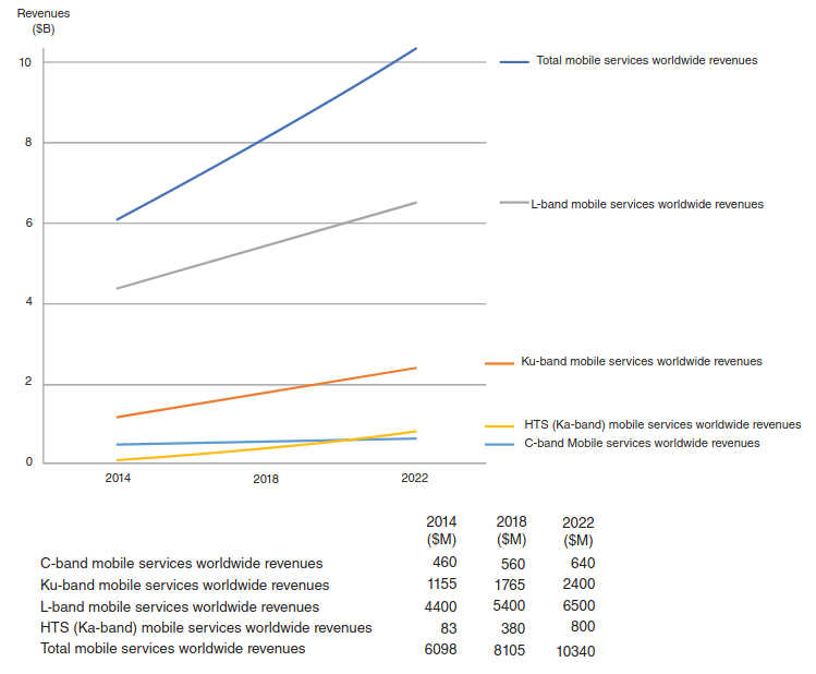
Satellite Infrastructure Providers
Major satellite operators, including but not limited to Inmarsat, Intelsat, and ViaSat, are in the process of bringing HTS capacity online over the most heavily traveled flight routes.
Inmarsat. Inmarsat This material is based on company information.x has, since its creation in 1979, been providing maritime, terrestrial, and aeronautical connectivity solutions over its fleet of geostationary satellites. The Aeronautical Services introduced on the second and third-generation 194 AERONAUTICAL MOBILITY SERVICES satellites (Aero H, H+, I, L, Mini M Aero, and Aero C) are referred to as “Classic Services.” The first aeronautical service, Aero H, was introduced in 1991 and has become the de facto standard of cockpit data communication for many of the world’s airlines and private aircraft, giving Inmarsat a reputation of reliability and longevity. With the addition of Swift 64, in 2002, the first high-speed data service was added to the portfolio and has since proven to be a popular solution for business and military users who need ISDN (Integrated Services Digital Network) data connectivity.
With SwiftBroadband, Inmarsat introduces a high-speed IP-based data service allowing even higher data throughput at a lower cost than the traditional circuit-switched services. SwiftBroadband is a Universal Mobile Telecommunications System (UMTS)-based service that is being provided over the fourth generation of Inmarsat satellites. The main difference between SwiftBroadband and earlier circuit-switched services such as Swift 64 is that it provides an “always on” background service and enables higher bandwidth than its predecessors. SwiftBroadband is being provided over a constellation of three Inmarsat 4 (I-4) satellites. The first two were launched in 2005 and the third was launched in 2008. The I-4 satellites are designed to provide higher bandwidth and to use the L-band spectrum more efficiently than previous generations of satellites.
This is achieved by using very narrow spot beams that allow efficient reuse of the available spectrum and by dynamically allocating resources to the areas where they are most needed, that is, the network operates in an analogous manner to a terrestrial Global System for Mobile Communications (GSM) network. Each of the I-4 satellites has 16 times the traffic-bearing capacity compared to their predecessors. SwiftBroadband is an IP-based packet-switched service that provides an always-on data connection of up to 432 kbps throughput per channel on a contended basis. This is the same model that terrestrial broadband services use, and for the end-user this means that the performance experienced will vary depending on the number of users transferring data at any given point in time. Inmarsat allows up to four channels to be used per aircraft. If an application needs guaranteed bandwidth it can request a streaming class, which will provide a predetermined quality of service to the application. If the application support it, the system is also able to provide dynamic streaming, allowing a dynamic change between streaming classes without change of Packet Data Protocol (PDP) context. The streaming classes available are 8, 16, 32, 64, 128 kbps and SwiftBroadband X-stream, which offer full channel streaming. The predetermined streaming classes can be combined with a total maximum of 224 kbps per channel. This theoretical maximum is dependent on a number of factors such as the class of terminal being used and the angle of elevation to the satellite.
The FleetBroadband service on the Inmarsat-4s will be complemented by Inmarsat Global Xpress™ (GX); the aggregate satellite network combines both Ka-band and L-band technologies to provide full global coverage. In 2010, Inmarsat awarded Boeing a contract to build a constellation of three Inmarsat-5 Ka-band satellites under the GX rubric. The Inmarsat-5 satellites are being built by Boeing and are based on the firm’s 702HP spacecraft platform. These satellites are part of a US$1,2 billion global satellite broadband network. Each Inmarsat-5 satellite antenna will provide 89 smaller Ka-band beams covering the portion of the Earth visible from its orbital location. The three Inmarsat-5 satellites needed for global coverage are being launched on Proton rockets by International Launch Services from the Baikonur Cosmodrome in Kazakhstan. The Inmarsat-5 F1 was launched in December 2013; this spacecraft has now been placed in its final GSO and has successfully completed testing of the platform and communications payload. The second and third spacecraft were scheduled for launch in 2014, providing full global coverage and service by the end of 2014. A fourth I-5 is on order from Boeing for delivery in late 2016. It will provide an early available spare in the unlikely event of a launch failure of any of the first three, but in the event the satellite is not required as a launch spare, Inmarsat is developing an incremental business case to support the launch of the fourth satellite to increase capacity and strategically enhance network coverage.
Some of the spacecraft features include the following:
- The I-5 body – at 6,98 m (22,9 ft), the height of a double-decker bus;
- User beams – 89 Ka-band beams generated by two transmit and two receive apertures;
- Spot beams – six steerable spot beams to direct additional capacity where it is needed;
- Solar arrays – a wingspan of 33,8 m (111 ft);
- Solar panels – five panels of ultra triple-junction gallium arsenide solar cells generate 15 kW of power at start of service and 13,8 kW by end of life;
- Station-keeping thrusters – a xenon ion propulsion system (XIPS) handles in-orbit maneuvering;
- Launch mass -6 100 kg;
- Mission life span – 15 years.
The spacecraft operate with a combination of fixed narrow spot beams that enable them to deliver higher speeds through more compact terminals plus steerable beams, so additional capacity can be directed in real time to where it is needed. GX aviation terminals will be provided exclusively by Honeywell, and Inmarsat is working with aircraft manufacturers to have both line-fit and retrofit solutions available.
The services offered by GX include in-flight broadband connectivity. The Ka-band service will be supported by the integration of an L-band FleetBroadband (FBB) backup service; with this approach, reliability will not be compromised in case of heavy rain, causing signal attenuation in the Ka-band, especially for maritime applications (aeronautical IFC services are less subject to rain-related issues, since flight below 10 000 ft is usually restricted to a few minutes after takeoff and a few minutes before landing). The goal of GX is to replace maritime, land, aviation, and government C– and Ku-band VSAT services offered by the company across the globe. The global network of Ka-band satellites will provide data rates up to 50 Mbps (20 cm antennas will support data rates of up to 10 Mbps; 60 cm antennas will support data rates up to 50 Mbps). GX uses smaller terminals – as noted – at a lower operational cost compared to the Ku-band offering. The uplink data rate can be as high as 5 Mbps. Passengers can connect to the GX service with smartphones, tablets and laptops, or any other Wi-Fi-enabled device.
GX is also targeted to maritime communications, with the availability of higher bandwidth on a consistent, end-to-end global basis. It enables advanced applications such as, but not limited to, video distribution, telemedicine, and video surveillance. For extra resilience, Inmarsat GX will be complemented by the FleetBroadband service on the Inmarsat-4s, which deliver 99,9 % overall network availability. As planes fly across the time zones, passengers will have a continuous, consistent service as traffic is handed seamlessly across each spot beam, and from one satellite to another. In 2014, Inmarsat announced that it would launch a Pan-European in-flight broadband service; British Airways was in talks to Become Launch Customer (Figure 11).
In a somewhat related matter in the Spring of 2014, Inmarsat proposed to International Civil Aviation Organization (ICAO) a free global airline tracking service over the Inmarsat network, as part of the anticipated adoption of further aviation safety service measures by the world’s airlines following the loss of flight MH370. This service is being offered to all 11 000 commercial passenger aircraft, which are already equipped with an Inmarsat satellite connection (virtually 100 % of the world’s long-haul commercial fleet). In addition to this free global airline tracking service, Inmarsat also offered both an enhanced position reporting facility to support reduced in-flight aircraft separation and a “black box in the cloud” service, under which – on the back of certain defined trigger events (such as an unapproved course deviation) – historic and real-time flight data recorder and cockpit voice recorder information can be streamed off an aircraft to defined aviation safety recipients. Inmarsat has been providing global aviation safety services for over 20 years and the ICAO, and International Air Transport Association (IATA) proposals represent a major contribution to enhancing aviation safety services on a global basis. Because of the universal nature of existing Inmarsat aviation services, the proposal from Inmarsat can be implemented right away on all ocean-going commercial aircraft using equipment that is already installed.
Intelsat. Intelsat’s Global Mobility Network This material is based on company information.x aims at providing reliable, high-performance aeronautical connectivity. The Ku-band mobility network delivers persistent, high-speed IP access for converged voice, data, and Internet applications – all on one contiguous global platform. Specially designed mobility beams, positioned across multiple Intelsat satellites, provide coverage across the world’s major flight routes. Automatic Beam Switching (ABS) technology ensures a seamless, always-on broadband connection as the aircraft travels between coverage areas. Reliable and secure, Intelsat’s mobility solutions are the clear choice for broadband and content providers operating in the aeronautical space.
Intelsat collaborated with Panasonic for the design of its first two HTS EPIC satellites (IS-29e and IS-33e) optimizing them for mobility applications. In order to meet specific traffic profiles (e. g., as shown in Table 1), Intelsat planned to provide spot beam coverage for high-traffic areas (Northern Atlantic and Pacific), along with wide beams for low-traffic areas. This hybrid HTS/wide-beam architecture improves end-to-end performance by reducing the number and effects of hand-offs between beams.
IntelsatOne Managed Mobility services offer access to mobile broadband through shared hardware and networking platforms and the global IntelsatOne terrestrial network. The service uses an infrastructure of 50+ satellites and 36 000 miles of terrestrial fiber. IntelsatOne Mobility allows customers to accelerate their broadband access through a hybrid service that combines space, teleport, shared networking platforms, and terrestrial data delivery.
Features of the service include the following:
- Reliable, always-on broadband access for voice, data, and video services;
- ABS allows for seamless transfer from one satellite to another while maintaining connectivity with continuous provisioning of the service;
- Pre-engineered solution with data rates from 128 to 4 096 kbps in C-band, and up to 50 Mbps in Ku-band;
- Global broadband solution from a single iDirect-based IntelsatOne platform, and;
- Defined IP rate for downlink and uplink channels for each customer.
Intelsat’s mobility services include the Mobility Transponder Services Space segment-only services based on Intelsat’s global fleet of satellites with coverage optimized for mobility users on the land, at sea, and in the air.
ViaSat. ViaSat as a core HTS infrastructure provider with its ViaSat-1 and -2 spacecraft was discussed in High Throughput Satellites (HTS) and KA/KU Spot Beam Technologies“Applications and Design Considerations of HTS Satellites” and earlier in this chapter, where the reader can refer back to, at this juncture. Service features are discussed later.
Iridium. We discuss iridium in Maritime and Other Mobility Services“Emerging Satellite-Based Mobility Applications for Maritime”.
Vertical Service Providers to Airlines
Gogo. Gogo a key provider of IFC, particularly ATG services. In 1997, Aircel started installing in-flight phone systems; in 2011 the company was renamed Gogo Inc. Using Gogo’s network and services, passengers with laptops and other Wi-Fi-enabled devices can get online on all domestic AirTran Airways and Virgin America flights and on select Air Canada, Alaska Airlines, American Airlines, Delta Air Lines, Frontier Airlines, United Airlines, and US Airways flights – as well as on thousands of business aircraft – bringing the total to more than 6 000 Gogo-equipped aircraft to date.
Gogo has three operating segments: commercial aviation, business aviation, and international aviation. In the United States, Gogo uses a terrestrial-based ATG network relying on its 3 MHz license in the ATG band. On the commercial side, Gogo has partnerships with North American airlines including Delta Air Lines, American Airlines, and US Airways. As of press time Gogo made broadband Internet available on more than 1 600 commercial aircraft; it also provided services to about 1 200 business jets. Gogo has filed an application to operate 1 000 Ku-band transmit–receive earth stations onboard aircraft in order to expand its in-flight broadband service offerings from the contiguous United States and portions of Alaska served by the current ATG network to provide continuous in-flight connectivity on transoceanic and other international flights. Gogo received Blanket Authority for Operation of 1 000 Technically Identical Ku-Band Transmit/Receive Earth Stations in the Aeronautical MSS, File No. SES-LIC-20120619-00574, Exhibit at 2 (filed June 19, 2012).
Gogo’s Ku-band-delivered in-flight service relies on three SES spacecraft. The SES-1 satellite enables airline passengers flying over the United States to access Gogo’s high-speed Internet service, while the SES-6 satellite with its mobility beams provides seamless coverage over the North Atlantic, and the SES-4 spacecraft serves Europe. The FAA recently certified Gogo to install Ku-band equipment on Airbus A330, Bombadier Challenger 300, and Boeing 747–400.
Gogo is expanding its connectivity business and is also providing MSS solutions to the business aviation market. In addition, Gogo is the largest reseller of Iridium services to the business aviation market. Reportedly Gogo also has plans to provide Ka-band services as a distribution partner of Inmarsat’s GX service.
The minimum requirements to access Gogo are a laptop with 802.11 a/b/g wireless capability (Wi-Fi) and a Gogo-supported web browser. Supported laptop browsers include:
- Google Chrome; Microsoft® Internet Explorer® 6, 7, and 8 (Windows® XP or Vista™);
- Mozilla® Firefox®, and;
- Safari™ on Mac OS® X.
Gogo Inflight Internet also works with any Wi-Fi-enabled smartphone or tablet device that runs Android®, Apple®, Windows®, and Blackberry® platforms. Supported browsers include Apple Safari, Google Chrome, Microsoft Internet Explorer Mobile (version 8 or above), and Mozilla Firefox.
ViaSat. Earlier we made use of public filing information related to ViaSat This material is based on company information.x to discuss important technical aspects of aeronautical services. Here, we provide some illustrative market information, with respect to ViaSat providing an integrated service to airlines.
In recent years, ViaSat has deployed an AMSS network using Ku-band FSS spectrum and has provided technology to support ESV applications using Ku-band FSS spectrum; as noted, Ku-band mobile network currently has a coverage area that spans the globe to support satellite communications on private jets and government aircraft, as well as ships and other ocean-going vessels. JetBlue, the current licensee of the 1 MHz of ATG spectrum through LiveTV, asserts that it has partnered with ViaSat Inc. for the provision of in-flight broadband services via satellite after determining that the 1 MHz of air–ground spectrum was insufficient to provide a quality broadband service. ViaSat also has contracted to install its air-to-ground broadband service onto aircraft operated by United Airlines, with 370 total aircraft scheduled to be online by the end of 2015.
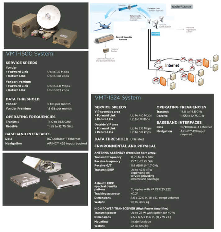
ViaSat, thus, offers two paths to the IFC market, as follows:
- Exede® In the Air for Commercial Airlines. Exede Internet service by ViaSat is a highly differentiated service capable of delivering 12 Mbps to the connected passenger giving them the best in-flight experience available. Commercial airlines can deliver a high-quality in-flight Wi-Fi experience at an affordable price. Connected passengers can work, surf, shop, and play up to 8x faster than competitive services giving airlines an advantage.
- Yonder® In-Flight Internet for General Aviation. In addition to HTS commercial airline services, ViaSat offers Yonder Service, which is an in-flight Internet connectivity service for business and VIP aircraft. Yonder offers a variety of service plans; it offer global high-speed coverage over continents and bodies of water (see Figure 12 for some design specifics and Figure 13 for the coverage map). Yonder and Yonder Premium use the VMT-1500 system, a very light, small-footprint Ku-band terminal. The VMT-1524 is designed for narrow and wide-body aircraft to support higher data rates and a larger number of users on Yonder VIP. In 2010, ViaSat announced a partnership agreement with JetBlue to deploy the first Ka-band commercial aviation broadband network on its more than 170 aircraft using ViaSat-1 in North America. In 2011, ViaSat announced that the YahSat subsidiary, Star Satellite Communications, will use YahSat 1B Ka-band capacity for the Yonder service. Also in 2011, ViaSat announced that it had entered into an agreement with Asia Broadcast Satellite to use Ka-band capacity in the Middle East using the ABS-7 satellite with 600 MHz of Ka-band capacity for fixed and MSSs as a part of ViaSat’s expansion of its Yonder mobile satellite network (see Table 8 for illustrative service plans).
Returning to the HTS-based IFC service, ViaSat has also developed a Ka-band terminal for aircraft that is designed for the high-capacity ViaSat-1 network. Just as ViaSat-1 and the associated Ka-band ground system technology fundamentally altered the economics of consumer-based satellite broadband services, the Ka terminal technology is expected to fundamentally alter the economics of aeronautical broadband by enabling service over ViaSat-1 at a lower cost per bit than previously possible. Because it leverages ViaSat’s existing Ka-band network, the mobile application of this technology can be deployed immediately. The antenna is a mechanically steered waveguide horn array antenna. As has been discussed in the earlier part of the chapter, recently ViaSat made an application to the US FCC for blanket authority to operate up to 4 000 technically identical transmit/receive earth stations to provide service in the United States using the 28,35–29,1 and 29,5–30,0 GHz portions of the Ka band for uplink communications and the 18,3–19,3 and 19,7–20,2 GHz portions for downlink communications.
The terminals are targeted to be mounted on commercial and private aircraft and will be used to provide two-way, in-flight broadband communications, including Internet access, for passengers and flight crew. The terminals will communicate with Ka-band satellites ViaSat-1 at 115,1° WL, WildBlue-1 at 111,1° WL, and ANIK-F2 at 111,1° WL. The terminals will communicate with:
- ViaSat-1 in the 18,3–19,3, 19,7–20,2, 28,35–29,1, and 29,5–30,0 GHz portions of the Ka-band;
- WildBlue-1 in the 19,7–20,2 and 29,5–30,0 GHz portions of the Ka-band, and;
- ANIK-F2 in the 19,7–20,2 and 29,5–30,0 GHz portions of the Ka-band.
Each of these satellites is already being used to provide service in the United States in these frequency bands.
Live TV. LiveTV, LLC is a wholly-owned subsidiary of JetBlue Airways Corporation that provides IFE, voice communication, and connectivity services for commercial and general aviation aircraft. LiveTV was expected to be the first service provider actually using HTS Ka-band capacity (from ViaSat over the United States and from Eutelsat over Europe) for in-flight connectivity services. The first commercial flight broadcasting LiveTV took place in 2000; hence, the company has years of experience. LiveTV provides both IFE products, such as seatback solutions, wireless IFE, and global and regional live television solutions, in addition to connectivity services in L-, Ku-, and Ka-band. The new Ka-band service will have JetBlue and United as first customers in the United States and Aer Lingus as the first announced airline in Europe. The service will be operated throughout the ViaSat Exede network over North America and Eutelsat KA-Sat in Europe.
OnAir. OnAir is a Switzerland-based company (in partnership between Airbus and SITA). OnAir provides IFC services in L-band through Inmarsat’s Swift-Broadband services discussed earlier. The provider has reportedly signed agreements with Inmarsat to provide in-flight connectivity services to commercial and business aviation markets using GX. OnAir first launched GSM services and later on Internet access services. OnAir serves commercial airlines, the VIP/business jet market, and the maritime market. It partnered with technology specialists such as Thales and has roughly 350 agreements with mobile network operators in 80 countries in addition to agreements with regulatory bodies.
Row 44. Row 44 Inc. is a US-based company that provides connectivity services over Ku-band satellite; it also provides live television and video on demand. In early 2013, Row 44, which provides in-flight broadband services for Southwest Airlines and several international carriers, announced that it had installed its service on its 400th aircraft. Satellite capacity is supported by Hughes’ network. The company expects to have global coverage by 2015.
AeroMobile. AeroMobile is a UK-based company that entered the market in 2007 specializing in in-flight GSM communications and voice and data services on mobile phone and tablets. It operates over Inmarsat’s L-band services and also in Ku-band (where more emphasis is expected in the future). Panasonic acquired a majority stake in 2012 in AeroMobile.
Panasonic. Panasonic Avionics, a key IFE manufacturer, also provides connectivity solutions. Panasonic makes use of Intelsat’s Ku-band HTS; it signed a long-term agreement with Intelsat for over 1 Gbps of capacity on IS-29e and IS-33e (at this time the firm is not pursuing Ka-band solutions). Panasonic Avionics provides in-flight broadband services to United Airlines and several international airlines. In 2013, United Airlines announced it had outfitted a Boeing 747 with Panasonic Ku-band satellite technology, and that it planned to install satellite-based Wi-Fi on numerous aircraft models in its fleet. The Panasonic in-flight Internet system makes use of a phased array antenna.
AT&T. AT&T (in addition to the DirecTV acquisition plan) is also planning to launch IFC services in combination with Honeywell by 2015. AT&T reportedly “sees a significant market opportunity” for IFC services. Some observers believe that AT&T’s service could impact the satellite opportunity for a longer term, depending on how AT&T deploys its network, for example, how much spectrum it will deploy. For the US continental market, Gogo is currently spectrum-constrained with just 4 MHz of spectrum (only 3 MHz in use); hence, Gogo is in the process of deploying satellite-based connectivity to supplement and/or replace the ATG service over time. However, a wireless carrier could create a more competitive service if it is willing to allocate larger spectrum bands to the ATG service and make the investments necessary to support the business, including network operations, billing services, and customer care. This is reportedly AT&T’s plan. The company aims to launch a nationwide ATG service in late 2015 using a number of alliances with the industry, including with Honeywell to provide hardware and service capabilities for a high-speed 4G LTE-based IFC. AT&T operates one of the major 4G LTE networks in the United States, and the company believes it has the capability “to transform airborne connectivity” by leveraging its expertise, spectrum, and financial strength.
Technology Providers Platforms. Platform vendors that supply the intrinsic on-the-ground technology include but are not limited to ViaSat, HNS, Gilat, NewTec, and Idirect.
End-systems: A number of vendors supply aeronautical terminals. Notable in that list is ViaSat Inc. The terminal is an integrated modem–antenna–radome set and is able to maintain a continuous link to aircraft in flight by performing seamless switching from beam-to-beam across spot beams from multiple Ka-band satellites.
The in-flight Internet system is certified by the FAA on A320 and Boeing 737 aircraft and is licensed for mobile operation by the FCC (Figure 14).


- [ATT201401] CNBC online magazine, April 28, 2014. Article stated that “AT&T announced plans to launch a high-speed 4G LTE-based, in-flight connectivity service stating that “we are building on AT&T’s significant strengths to develop in-flight connectivity technology unlike any other that exists today, based on 4G LTE standards.”
- [AZZ201001] T. Azzarelli, L-band Spectrum Process, ESA Presentation, 27 May 2010.
- [BAL201401] E. Ballard, R. Wall, Wall Street Journal, June 5, 2014.
- [BOW201301] S. Bowles, “Movie ticket prices jump to all-time high”, USA TODAY, July 23, 2013.
- [CAS201201] High Throughput Satellite Networks, White Paper, June 2012. CASBAA Executive Office 802 Wilson House 19–27 Wyndham Street Central, Hong Kong.
- [COM201401] Comsat Laboratories, a division of ViaSat, Informational Material, 20511 Seneca Meadows Parkway, Suite 200, Germantown, MD 20876.
- [FCC201301] Application of AC BidCo, LLC, Gogo Inc., and LiveTV, LLC, WT Docket No. 12–155, Federal Communications Commission, For Consent To Assign Commercial Aviation Air-Ground Radiotelephone (800 MHz band) License, Call Sign WQFX729, Memorandum Opinion And Order; Adopted March 29, 2013, Released March 29, 2013.
- [HOL201401] M. Holmes, AT&T Exec Talks to Via Satellite About In-Flight Connectivity Plans, Via Satellite/Satellitetoday.com, May 23, 2014.
- [INM201401] Inmarsat marketing materials on Global Xpress.
- [INT201401] Intelsat marketing materials on EPIC.
- [ITU201101] ITU-R, Report ITU-R S.2223: Technical and operational requirements for GSO FSS earth stations on mobile platforms in bands from 17.3 to 30.0 GHz (Question ITU-R 70-1/4) (2011)
- [NSR201201] Mobile Satellite Services, 8th Edition, NSR, 2012.
- [RUI201301] N. De Ruiter, B. Prokosh, High Throughput Satellites: The Quest For Market Fit — A vertical market analysis of major drivers, strategic issues and demand take up, An Euroconsult Executive Report. November 2013. 86 Blvd. Sebastopol, 75003 Paris, France.
- [USP201001] US Patent US 7787819 B2, “Ground-based beamforming for satellite communications systems”, Publication number US7787819 B2, Publication date Aug 31, 2010. John L. Walker, Rolando Menendez, Douglas Burr, Gilles Dubellay inventors.
- [VIA201201] ViaSat, Inc. EXHIBIT A to FCC Filing for Ka band Aeronautical Antenna, Public Interest Statement and Waiver Requests. 2012, U.S. Federal Communications Commission.
- [WLI201301] W. Li, R. Roithner, C. Fargier, Prospects for In-Flight Entertainment And Connectivity – Sector dynamics, analysis and forecasts addressing the IFEC market for commercial airlines and business aviation. An Euroconsult Executive Report. April 2013. 86 Blvd. Sebastopol, 75003 Paris, France.