The manufacturing of fiberglass boats begins with the design phase, where detailed plans for the boat are developed, considering factors like size, shape, and intended use. Once the design is finalized, a full-scale model or plug is constructed. From this plug, a mold is created, often using fiberglass.
The next step is the application of the gelcoat, which forms the smooth outer surface of the boat. This gelcoat is applied to the mold and allowed to cure, providing a glossy and durable finish. After the gelcoat has cured, layers of fiberglass mat or woven roving are applied. These layers are saturated with resin, typically polyester or vinyl ester, and then rolled to remove air bubbles and ensure an even distribution of resin. This process is known as lay-up.
Once the initial layers of fiberglass and resin have cured, additional layers are added to build up the desired thickness and strength. In critical areas, such as the keel or transom, extra reinforcement is applied. For added strength, some manufacturers use core materials, like foam or balsa wood, sandwiched between layers of fiberglass. This sandwich construction technique increases stiffness without significantly adding weight.
After the hull is constructed, it is removed from the mold, and the interior components, such as bulkheads, stringers, and deck structures, are installed. These components are usually bonded to the hull using adhesives or fiberglass tabbing. The deck is then attached to the hull, typically using mechanical fasteners and adhesive bonding, creating a watertight seal.
Finally, the boat is outfitted with hardware, plumbing, electrical systems, and other accessories. The final steps include quality control inspections and testing to ensure the boat meets safety and performance standards.
Design features of fiberglass boats are crucial to their functionality and appeal. Hull shape, for example, influences the boat’s performance in various water conditions. V-shaped hulls are common in powerboats for their ability to cut through waves, while flat-bottomed hulls offer stability in calm waters. Additionally, the placement and design of stringers and bulkheads contribute to the overall strength and rigidity of the boat.
Attention to detail in the design phase, such as incorporating storage compartments, ergonomic seating, and efficient layout of controls, enhances the user experience. Innovations like integrated swim platforms, sleek cabin designs, and advanced navigation systems also add to the boat’s appeal and functionality.
How a Fiberglass Boat is Made
As I mentioned earlier, the fiberglass sailboat industry is a relatively small one. Actual production in terms of units rarely exceeds six hundred per year for even the largest manufacturer of cruising sailboats in the 26- to 40-foot range.
The low production is due to two factors:
- First, the market is small – only about four thousand new sailboats in this size range are bought each year in the entire country.
- Second, each boat is largely built by hand, much the way cars were before Henry Ford.
Contrary to what many people think, a fiberglass boat is not a homogeneous piece of plastic, such as a Clorox bottle or a boat that you put together from a plastic model kit. A fiberglass boat is a combination layer cake and jigsaw puzzle: each layer has to be put in by hand and the entire boat must be assembled by hand.
You might think from my remarks that the largest part of the cost of a fiberglass sailboat would be the labor involved, but this is not the case. It only takes, for instance, about three hundred man-hours to build a 30-foot auxiliary sailboat from start to finish – about ten days in a well-run plant.
The cost of these man-hours is only about 25 percent of the cost of the boat. The other 75 percent is primarily materials, so you can see that a major way to reduce the cost of a boat is to reduce the amount of material in the boat – or to substitute cheaper materials, or to opt for a less plush interior in order to maintain a strong hull.
Once the boat is put together, however, it is very difficult to determine how thick the hull is, that is, how much material went into it. There are ways, though, to make reasonable deductions about this and we will get to them in the next chapter. For now, let’s see just how a fiberglass sailboat is made.
The process begins with the decision to come out with a new model. The general size of the boat and desirable features are indicated to the designer or design group, who produce preliminary drawings for the top management or whoever is responsible for the overall direction of the new boat – sometimes these plans are discussed with the dealer network for their ideas, criticisms, and suggestions. Over a period of months, the design is finalized and the job of getting it into production begins.
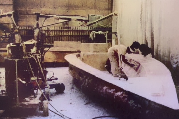
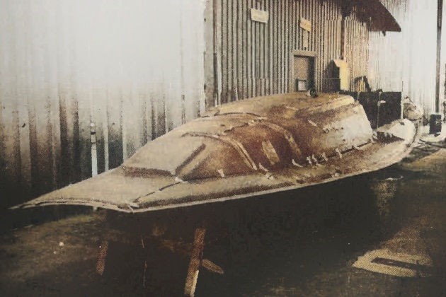
The first thing that is actually built is what is called the hull plug. This is usually made upside down of wood in very much the same manner that a wooden boat is constructed. When complete, it is an exact model of the hull of the new boat. This is faired, sanded, polished to a high finish, and then waxed. A hard, enamellike coating, called gel coat, is sprayed onto the waxed plug and then sheets of fiberglass are laid onto the gel coat and saturated with resin, which hardens and forms a skin over the plug about one-eighth of an inch thick.
More layers of fiberglass are put on, saturated with resin, and allowed to harden. One of the characteristics of the fiberglass sandwich that is being built up over the plug is that it is quite flexible; many layers are needed to ensure rigidity. When the desired thickness is reached – about a half-inch or so – a framework is built around the structure to further ensure stiffness and it is separated from the plug.
This is the mold for the hulls of the new boat. Often, if the new model is expected to sell in large numbers, another mold will be made. In a similar manner, molds are made for the deck and other components, such as the cabin sole (floor), galley, and berth platforms.
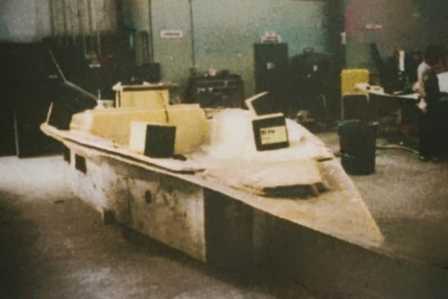
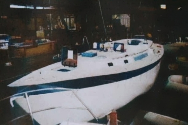
Space is now allocated in the plant and the molds are moved to the far end, or beginning, of the production line (Fig. 1 and 2).

Before actual construction of a boat begins, the mold is thoroughly cleaned and heavily waxed to ensure that the hull, when completed, will come out of the mold and not stick in it.
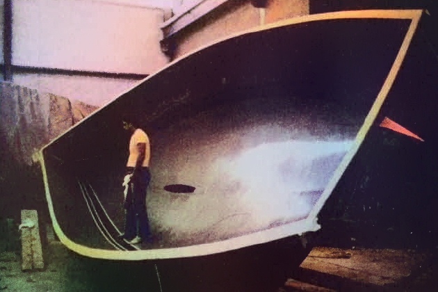
The first layer to go into the mold is the outermost layer of the finished hull, the gel coat. This is the layer that has the color of the finished boat, although its main purpose is to provide a hard, dense layer that will resist abrasion and prevent water penetration. This is sprayed onto the inside surface of the mold by a man operating a special spray gun that does not use air. This ensures that the gel coat goes on as densely as possible.
Now, since this gel coat is very hard when dry, it is also quite brittle. Fiberglass is flexible, so it is necessary that the gel coat be quite thin. Too thick and it may craze, that is, develop hairline cracks as the completed boat flexes in use. This is an area where good supervision and operator skill are required.
After the gel coat has had time to set, the first layer of fiberglass is laid into the mold. This is usually the type of glass known as «mat», which consists of loosely woven strands about four inches long. In appearance, it is a little like straw. The mat is saturated with resin and any air bubbles are rolled out by hand.
Read also: How to Choose the Best Selling Price for Your Boat
Mat can also be applied in another way, and that is by a machine that takes a thread of fiberglass, cuts it into short lengths, applies resin, and blows the strands onto the mold. This is the infamous chopper gun.
Its advantage is that it saves time, but the thickness of the mat laid down is controlled by the operator and so may be applied too thick or too thin. Many builders use a combination of cut mat and gun. For structural parts of the boat, such as hull and deck, they will have the mat cut out of large rolls and placed by the mold where they can then be counted as they are put into the boat to ensure that a hull of the designed thickness is built.
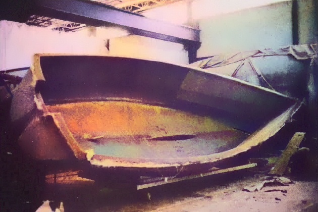
The next layer into the mold is a layer of woven roving, which is made of thick fiberglass threads woven together much like a cane chair. Because the threads have a slick texture, the material has much the same look and feel as medieval chain mail. This material is the strength of the boat; the principal reason for the mat is to bind the layers of roving together. Because of its slick texture, two layers ofroving will not bind well directly to one another.
Construction is continued by working resin into alternating layers of mat and roving until the specified hull thickness is reached (Fig. 3).

This will vary from the deck edge to the keel. On a 30-footer, the thickness at the deck will probably be about one-quarter of an inch, while at the keel it may be as much as three-quarters of an inch. This, of course, varies from manufacturer to manufacturer and is very difficult to ascertain. Again, there are ways to form some conclusions; we’ll get to them in the article «Instant Naval Architecture».
Just as a personal observation, I always like to see roving be the last layer inside the hull, because that means the hull has been finished with a strength layer rather than a fill or binder layer.
As I have indicated, the roving-mat-resin sandwich is basically flexible. So, to achieve a desirable level of stiffness, many layers have to be built up, depending upon the engineering requirements. For example, the hull needs to be most rigid where the concentrated weight of the ballast is carried. It can be thinner at the deck edge because considerable stiffness will be imparted by the attachment of the hull to the deck.
There are other ways to achieve rigidity in a hull. One of these is to use a different type of roving. Woven roving is relatively cheap and, even though many layers have to be built up to achieve stiffness and strength, it is still cheaper than what is called unidirectional roving.
In unidirectional roving, instead of having the thread bundles run at right angles to each other, they all run longitudinally and are only lightly stitched together crossways. The effect is like piling up straws, one on top of another. You get a light structure that is very rigid longitudinally.
Using this material, it is possible to build a much lighter hull without sacrificing structural strength. Even though this hull will be more expensive than one employing the more traditional roving, lightness has its advantages (see article «Instant Naval Architecture») and several builders use this method to achieve it.
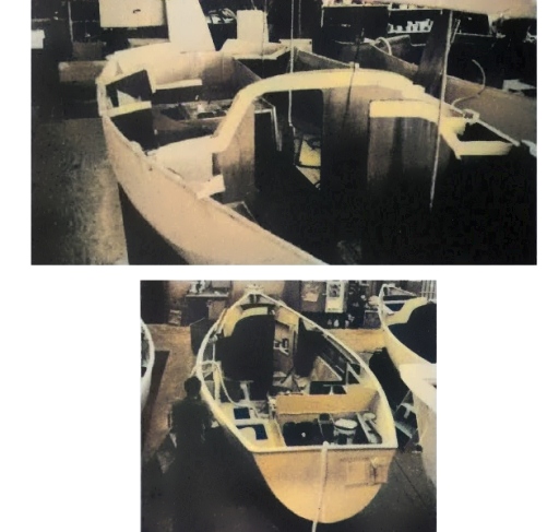
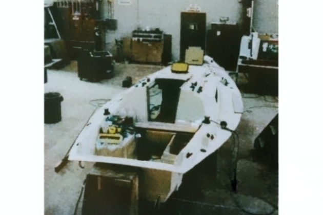
To return to our hull. At this point, it is complete and still inside the mold. Before it has completely cured, while it is still «green», certain structural members are installed. These usually consist of plywood, gores, gussets, and knees that are glassed onto the inside of the hull to reinforce the stem and transom, for example, and to provide the bases onto which the chain plates will be bolted. It is important that these items be done before the hull is completely cured, for in that way the strongest bond is made.
This process is called the «secondary bonding» (Fig. 4) and is an important area to look at when you are evaluating the quality of the workmanship that went into the boat.
These secondary bonds should be smooth, without bubbles or «icicles» (sharp strands of cured glass and resin), and should flow almost imperceptibly onto the final layer of the hull itself. Done this way, maximum spreading of the loads on these members is assured and, therefore, maximum strength.
At this stage, the engine beds and the stern tube for the propeller shaft are often glassed in, too. If the ballast is going to be contained within the cavity of the keel, it is placed and sealed in with:
- roving,
- mat,
- resin.
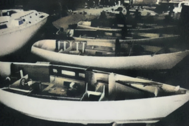
Once this work is done, the hull is removed from the mold, placed on a cradle, and wheeled from the molding area to the line along which the final work will be done.
Unlike a car production line, a boat is not continuously moving. Rather, the boat sits in the same spot – often for days – while certain things are done (Figs. 4 to 8).
Then it is moved ahead to another stage, where it may also remain for a day or more.
Indeed, some builders only move the hull once – out of the mold – and not again until the boat is complete and ready to go out of the door.
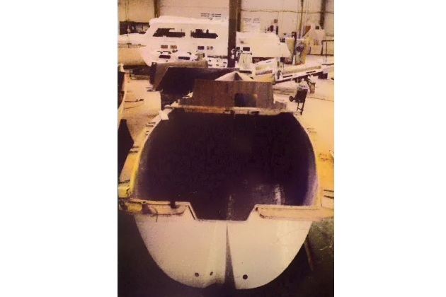
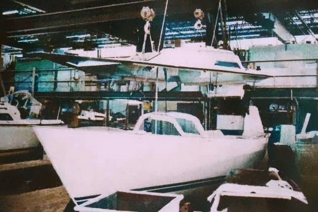
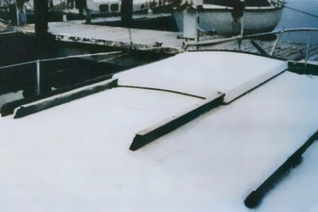
Now, while the hull was being molded in one area, the deck and hull and deck liners were being molded in another (Figs. 9 to 11).

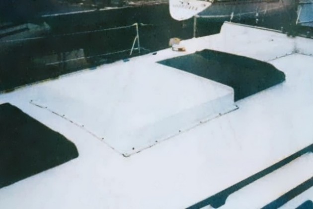
Unlike the hull, which is usually composed of many layers of glass, the deck is a sandwich of glass and either plywood or balsa. This is because the deck needs to be light and more rigid than the hull, and this is the most practical way to achieve these two qualities.
Lightness is sought so that the weight of the deck, being up high, will not work any more than necessary against the stability of the boat; rigidity is wanted because it adds greatly to the strength of the hull-deck combination. Besides, who would want to walk around on a spongy deck?
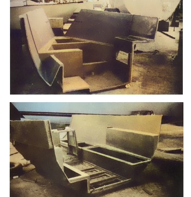
Usually, the deck is turned over and, while the engine and structural bulkheads (walls) are being installed in the hull, the headliner is bonded to the deck (Fig. 12).
This liner is not a structural part of the boat. Its purpose is to cover up the underside of the deck so that a pleasing, finished ceiling is overhead in the completed interior. Often, the headliner is made entirely of chopped mat by the chopper gun.
Once the headliner is on, various items of deck hardware, such as stanchions, cleats, and winches, are attached (Fig. 13).
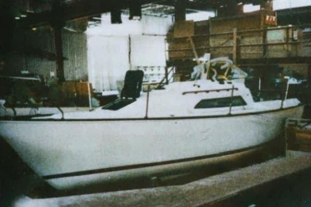
The cockpit is also a part of the deck mold, and, if the boat is to have a steering wheel, this is mounted while the deck is upside down. Now the deck can be attached to the hull (Figs. 14 to 16).
It is at this stage that the procedures of boat manufacturers begin to diverge from one another.
If the boat is to have great attention paid to the interior, the deck and hull will be mated and then a crew of cabinetmakers will take over the boat and build, item by item, the berths, lockers, drawers, and so forth and install and finish them. Obviously, this process is costly; a boat done in this manner can have up to half of its total cost represented by the interior.
For this reason, most production builders do as much of the interior as they can elsewhere in the plant and install the interior before joining the hull and deck. In this way, much time and labor are saved; there is little post-finishing so that, once the hull and deck are joined, the boat is virtually complete, needing only the mast and boom from the rigging shop and, possibly, the berth cushions from the upholstery shop.
Now, at this point we have built boat Number 1 of a hypothetical series of boats (Fig. 17).

It is here that industry practices again diverge and vary. With Number 1 out of the mold, some builders would have immediately begun Number 2 so that, by the time Number 1 was ready to go out the door, Numbers 2, 3, 4, and 5 would probably be lined up in various stages of completion – or disarray.
A more conservative practice, however, is followed by other builders and that is this: before they start Number 2, they completely assemble Number 1, rig it, launch it, and sail it to see if, for example, the rig is in the right place so that the boat does not have an incurable weather or lee helm. Normally, with an established, experienced builder, the design is fine and so series production begins.
But sometimes little kinks do turn up and needed changes can be made before the boat is sold to the retail buyer (you). It’s so nice to know, when you set off on your first sail in your new boat, that someone – one hopes the designer – has been out in the beast before you and that you are not playing test pilot to somebody’s dream of what a boat should be. That is to say that you have bought a verified, true boat and not merely what someone hopes is a boat.
Clues
As you can gather from the preceding point and pictures, once the boat is all together it is very difficult to determine some things – such as how thick the hull is. Since you are going to be shopping among completed boats in a dealer’s showroom, you are going to have to assess the construction from what you can see. These things I call clues; they are basically the things you can see as you move around the boat. We’ll start from the outside.
Exterior of Hull
What should the outer surface of the boat hull be?
The exterior surface of the hull should be as dense, smooth, hard, and shiny as the surface of a new billiard ball. If it looks like the skin of an orange or has a dull, porous look, it is a sign of either inferior material (gel coat) or incorrect application – possibly due to inexperience on the part of the spray-gun operator, poor supervision, or the fact that the hull mold needed cleaning and refinishing. Put your eyes right up to the surface – as close as you can focus. Look along the hull from the bow and stern and try to catch it in a light that glances from the hull rather than strikes it from abeam.
In addition to having a good surface texture, the entire surface of the hull should sweep in fair curves from bow to stern with few, if any, hard spots. A good way to judge the fairness of the hull is to look from underneath along the rail line where hull and deck join – to see that it is an even curve from bow to stern without large, flat sections. Occasionally, a bulkhead will cause a crease to appear in the exterior of the hull; this generally is not serious if there are not too many of them. This is a test of the care with which the boat was built. If you are considering a dark-colored hull, try to find another from the same builder in the same dark color, as black or dark hulls magnify every flaw of this kind.
I personally like to see a slight print-through of the woven roving in the hull, because that tells me it is there and probably in sufficient quantity. This material, you remember, is the strength component of the fiberglass sandwich. If, however, the hull looks, at a casual glance, like a waffle, excessive heat was allowed to build up in the mold during construction and the appearance and the value of the boat suffer. Print-through of the roving pattern should be visible only to a very careful scrutiny from close range.
While you are outside the boat, it might be a good idea to find out what the ballast material is – ask if the brochure doesn’t say – and how it is attached to the hull. Lead is the densest readily available material and so it is the preferred ballast material. Being dense, a relatively great weight can be concentrated in a small volume placed low where it will contribute best to the stability of the boat.
I like to see the ballast either attached to or set inside a keel which is formed as part of the hull, in the manner that a branch grows from a tree. This spreads the load over a larger area of the bottom of the hull than would be the case if the ballast were simply attached directly to the bottom of the boat. If the keel is external to the hull, the seam should be virtually invisible and the bolts (visible in the bilge) massive and spread over a wide and wellreinforced area.
Lead is expensive and so, in many of the smaller production boats, cast iron is used. There is a little more maintenance with this material because, after a season in the water, the iron is going to show rust spots that will need to be wire-brushed away and primed before a new coat of bottom paint is applied.
Often these days, the cast iron forms the entire keel of the boat and is bolted directly to the bottom of the hull. If you are looking at a boat with such a keel, check inside for substantial reinforcement to take the concentrated load of such an installation.
While you are under the boat, you should try to determine the size of the rudder stock, the metal shaft to which the rudder is attached to the boat. On a freestanding spade rudder, it needs to be substantial because it takes the entire steering load.
Shopping is purely a case of comparing items on one boat to the same things on another. If you find one boat that has a substantially smaller rudder stock than another, it may indicate – along with other facts – that the builder is skimping. Similarly, look inside to see how the builder engineered the stock’s entry into the hull. The structure should look substantial. Have the wheel or tiller put over fully from one side to the other and look and listen for any odd motions or noises as the rudder system comes to its stops.
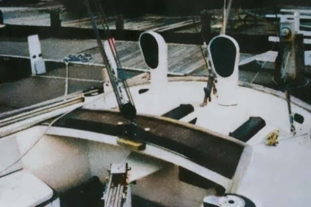
In the Cockpit
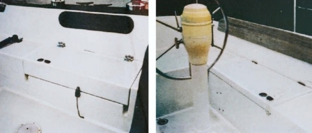
One of the first things I look at when I get into the cockpit is the seat lockers – not how capacious they are, but how the hatches are made. I like to see deep scuppers around the hatch to keep out as much water as possible, and I like to see deep sides on the hatch for the same reason. I look at the size of the hinges (Fig. 18) and find out whether they are bolted on or simply screwed or riveted in place.
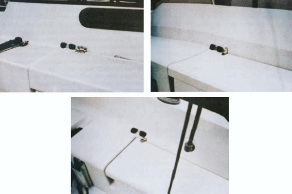
Their edges also can tell you things (Fig. 19).
Inside the seat lockers is one place you can usually see the inner face of the hull and, as I said, I like it if the last layer is roving instead of mat. The inside of the lockers also reveals whether the general level of fiberglass work is neat or sloppy.
While in the cockpit, check the size (i. e., diameter) of the lifelines. You will be amazed how much this varies from manufacturer to manufacturer. I like hefty lifelines – at least a quarter of an inch in diameter. Take hold of a stanchion and pull firmly. Fiberglass is flexible, but the deck should not move more than fractionally – here again, it’s a matter of comparing one boat to another more than a matter of absolutes. If you hear some crackling noises while you do this, it’s normal for fiberglass – it’s the brittle gel coat making noises for the same reason cellophane does when you crumple it.
Look at the sizes of the cleats and winches. Are they substantial compared to others you’ve noted? Are they through-bolted?
On Deck
Look at the size of the chain plates, the metal bars to which the shrouds are attached when the mast is installed. How do they compare with others you’ve seen on the same size boat? How strongly are they secured below deck? They must withstand enormous strain.
I remember once I was trying to sell a certain 30-footer to a man who had obviously never noticed chain plate sizes before. The 30-footer was tied up next to a 40-footer and I asked him to compare their chain plates. He was amazed to find that those on the 30-footer were just as large!
Now, the 30-footer was certainly overbuilt in this area, but this is an area that I like to see overbuilt. Those bars of stainless, well tied into the hull, are what keep the entire Comprehensive Collection of Common Sailboat Rig Types and Designsrig in the boat. Overbuilding in this area may indicate a respect for the sea that will also show up in overbuilding in other areas.
Look at the hatches (Fig. 20).
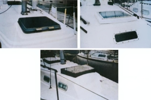
Do they seem as if they will do a good job of keeping water out? How do they compare with others?
How does the toe rail look? If it is teak, is it (compared to others) substantial or skimpy? The hull and deck of many boats are fastened together through the toe rail, so if it is wood, there should be some heft, or «meat», to it. The same considerations hold if the toe rail is a metal extrusion.
Inside
As you go below, into the boat, take a look at the companionway hatch (Figs. 21, 22, and 23).

Does it slide easily? Does it seem well made? Strong enough for a person to stand on safely? Is there a spray-shielding cover in front of it to keep water from coming in under the lip?
Once you are below, take a close look at the joinery work. Is it nicely fitted together with close, even joints, or is the craftsmanship of the cabinets (called «quality») just a layer of varnish that feels bumpy and sandy to the touch? How about the overhead? Is it smooth and fair? If it is not a durable material, such as fiberglass, will it be easy to remove or replace if it gets stained by a leak or ripped by accident?
Look in the hanging locker (closet). This is one place in the boat where you can usually see enough to assess the secondary bonding.
Usually, this is where the buttresses are to which the chain plates are bolted. Is it smooth and fair, without «icicles» and trapped bubbles? Is it neat work? Does the bulkhead (wall) seem to be well bonded to the hull with roving? The tests here are the same as for any secondary bonding.
The hull-deck joint is usually visible from inside the hanging locker, and in the figure 24 above I have arranged (in order of probable strength) nine sketches of typical methods of attaching hull and deck.
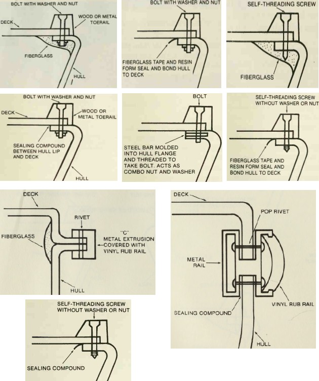
As I indicated earlier, this is the largest seam in a fiberglass boat, and it is important that it be not only watertight, but strong, since the deck contributes mightily to the finished strength of the whole boat. Consider the size and spacing of the bolts or screws used in any of these methods and compare boat to boat.
As a way to get an overview of the structural parts of the boat and to clarify the whole thing in your mind, you might imagine that the boat is a shoe box. You know that without the lid (deck) on the shoe box, its sides are very floppy. You can see that if you put the lid on the box and fasten it to the sides of the box, the box will become stiffer and stronger.
In addition to the lid, a heavy keel is fastened to the bottom of the box. You can see, therefore, that the bottom of the box has to be thicker than the sides and may also need internal bracing to help stiffen the bottom and spread the load. Similar considerations apply to the attachment points (chain plates) for the shrouds (the wires that support the mast). These attachments, called buttresses or gussets, should be large enough to spread the loads and carefully bonded to the inside of the hull to ensure maximum strength.
The next thing you may want to check are the through-hull fittings, the fittings at those points where the drains from the sinks and the toilets go out through the hull and where the engine cooling water and toilet flushing water come in. There should be a shut-off valve at each of these points, and the most important point to note is whether or not the fitting is mounted on a backing block to properly distribute the loads imparted in mounting and using it.
It will be interesting: Self-Survey Criteria for the Basic Boat
Over the years, great argument has raged as to whether these valves should be seacocks or gate valves. Gate valves work like the water valves outside a house. They have a circular handle and require several turns to open or close fully. Seacocks, on the other hand, have a lever which only has to be moved ninety degrees from full on to full off. This means they can be closed more quickly than a gate valve and, since it is a good idea to close the through-hulls – except the cockpit drains, of course – when leaving the boat, seacocks are closed more conveniently.
On the other hand, gate valves are manufactured in the millions for many uses, while seacocks are made only in the hundreds for yachts. Seacocks are much more expensive than gate valves, and I see no objection to gate valves, as long as they are properly mounted. Seacocks also are subject to being closed by vibrations set up by the engine, and so some manufacturers have taken to using gate valves at the cockpit drains and engine water intake and seacocks elsewhere.
The main point is that each through-hull should have a shut-off valve. That way, if a hose does happen to pop off some fine day, you’ll be able to stop the flow of water into the boat. Stopping the flow is what these valves are all about anyway and, since hoses have a habit of popping when the boat is unattended, their accessibility is more important than their type. If you really want to be tough on a boat, see if you can reach all the valves readily and without lifting anything larger than a 9 × 9-inch access panel. Few boats can pass this test.
Masts
There are two ways to install a mast: on the boat or into the boat. A mast mounted by cutting a hole in the top of the cabin and setting it on the bottom of the boat has obvious advantages of strength and simplicity. In boats under about 30 feet, though, the spar can be intrusive, so quite often the mast is mounted on the top of the cabin. This means that an interior support structure has to be engineered to transfer the loads to the bottom of the boat. This can be done in several ways, but the key item to check is that the vertical support or supports under the mast be continuous from the underside of the deck to the bottom of the boat.
If the under-deck support is a single vertical column (can be metal or wood), look (or feel) under the cabin floor to find out if the space has been filled in or not. If the vertical support has been divided between the jambs of a doorway, do the same.
Often a boat will go through many years of normal service without this shortcoming causing trouble, but eventually things will start to sag and, with the warranty expired, the owner (you) is going to pay to fix it.
Engines
Most sailors tend to look vague or pained when the subject of engines comes up. I must admit that I don’t understand engines fully. I have found, though, that by adopting a god-slave relationship with the engine (it the god, I the slave) and offering up regular sacrifices of fresh filters and clean oil, we are able to live on the same boat and carry out our respective duties. To facilitate this relationship, good access to the engine is required and this is definitely something to check.
Normally, the engine is tucked away under the cockpit and is reached via the seat lockers and/or by removal of the companionway ladder. In some boats, the engine is in the main cabin under a seat; this is terrific for accessibility, but means a somewhat noisier and warmer cabin when under power.
This is just one of the many trade-offs involved in buying any boat. You probably can’t have a proper engine room in any sailboat less than 40 feet and even then only if it has a center cockpit. So, the thing to do is see if normal servicing can be done without dismantling the entire galley. Try to put your hand on the oil dipstick. Go through the motions of changing the oil filter or a drive belt for the alternator or water pump. Most boats are difficult in this regard, but some are worse than others and, after looking at a few engine compartments, you’ll be able to spot the builders who are at least trying to ease a difficult situation. The neatness (or lack of it) with which the wiring is run is also a clue to the builder’s general standards.
Since sailboats only travel at one speed (slow), they don’t need a great deal of power and some manufacturers, to save money, will use smaller engines than others. So, this is another place a comparative check can be made. While it only takes about 10 horsepower (HP) to push a 35-footer through the water at 6 knots, it makes a lot of difference to your ears and nerves whether this 10 HP is being generated by a one-cylinder engine running at 3 600 RPM or a four-cylinder engine running at 1 800 RPM. The first is not unlike hugging a jackhammer, the second more like sitting on a washing machine. Neither is really fun; but the second instance is closer to it.
Ventilation
In 1977 it became federal law for new yachts with gasoline engines to have exhaust fans (called «blowers») and air inlet ducts for the engine compartment. This law does not apply to dieselpowered pleasure boats (which goes a long way to explain the current preeminence of diesel auxiliaries), but a conscientious builder will install such a ventilation system anyway, and once you have lived with a diesel for a while, you will appreciate the ducting and blower. Diesels are so smelly that having something to extract the odor and let in fresh air is a blessing.

As a matter of fact, it is a widespread practice when running a diesel-powered boat to turn on the blower as soon as the engine is started and to let it run until about five minutes after the engine is shut down.
If a boat has this ventilation system, the ducting is usually visible in the engine compartment. If you don’t see it there, look for cowl vents («ears») on the transom (Figs. 25, 26, 27).
If you can’t spot the fan, check the brochure or ask the broker to point it out to you.
Owner’s Manual
Earlier I mentioned one tough test: see if you can easily get to and operate the seacocks. Here’s a test that is actually cruel: ask to see the owner’s manual.
Some manufacturers do make an attempt to put together an instruction kit for their boats, but many simply present you with a Ziploc plastic case stuffed with the miscellaneous warranty cards and installation instructions which came with the pumps, toilets, switches, and washbasins when they were delivered (by UPS) to the boat builder.
If you really have a little of the grand inquisitor in your soul, an inquiry into the language of the engine manual may prove interesting. Engines are often imported – along with their native operating directions.
In any case, I think you’ll find even the baldest comparison of owner’s manuals illuminating and almost embarrassingly revelatory – rather like eavesdropping.
A final set of items that you can use to compare boats and builders is the recommendations of a group called the National Fire Protection Association. Their booklet No. 302 has their standards for commercial and pleasure vessels and, while they do not have the force of law, are generally good commonsense ideas anyway. Many insurance companies expect marine surveyors to point out omissions of these in a used boat and may require compliance before they will issue coverage, so it’s a good thing to check before you buy, as, eventually, you’ll sell and it may become an issue then.
In any case, the four most important items are:
- powered and natural ventilation ducting to the engine compartment;
- lightning-grounded rigging;
- batteries in acid-proof cases with covers and tie-downs;
- reachable fuel shut-off valves at the tank top.
A builder who omits these items could probably reduce the retail price of the boat and thus have an (apparent, of course) advantage in the marketplace.
While you are looking around for a new boat, you are going to be faced with a lot of opinion, advice, How to Purchase the Perfect Boat: Evaluation to Final Salesales pitches, and a certain amount of bull. The purpose of this chapter has been to show you that you don’t have to rely entirely on others in selecting a boat.
By looking at certain specific real things, comparing, asking questions, and using your head, you can come to solid, rational conclusions about any specific boat that interests you. Also, if you show some knowledge, it can discourage some of the baloney.

- Cruising World, Subscription Service Dept., P. O. Box 953, Farmingdale, NY 11737.
- Motor Boating & Sailing, P. O. Box 10075, Des Moines, IA 50350.
- Multi-hulls, 421 Hancock St., N. Quincy, MA 02171-9981.
- Nautical Quarterly, 373 Park Avenue South, New York, NY 10016.
- Sail Magazine, P. O. Box 10210, Des Moines, IA 50336.
- Sailing, P. O. Box 248, Port Washington, WI 53704.
- Small Boat Journal, P. O. Box 400, Bennington, VT 05201.
- Soundings, Soundings Publications, Inc., Pratt Street, Essex, CT 06426.
- The Practical Sailor, Subscription Dept., P. O. Box 971, Farmingdale, NY 11737.
- Wooden Boat, Subscription Dept., P. O. Box 956, Farming-dale, NY 11737.
- Yacht Racing/Cruising, North American Building, 401 North Broad Street, Philadelphia, PA 19108.
- Yachting, P. O. Box 2704, Boulder, CO 80321.
- Beiser, Arthur. The Proper Yacht, 2nd ed. Camden, Maine: International Publishing Co., 1978.
- Chapman, Charles F. Piloting, Seamanship and Small Boat Handling, 56th ed. New York: Hearst Marine Books, 1983.
- Coles, Adlard. Heavy Weather Sailing, 3rd rev. ed. Clinton Corners, N. Y.: John De Graff, Inc., 1981.
- Pardey, Lin and Larry. Cruising in Seraffyn and Seraffyn’s Mediterranean Adventure (W. W. Norton, 1981).
- Roth, Hal. After 50 000 Miles (W. W. Norton, 1977) and Two Against Cape Horn (W. W. Norton, 1968).
- Royce, Patrick M. Royce’s Sailing Illustrated, 8th ed. Ventura, Calif.: Western Marine Enterprises, Inc., 1979.
- Kinney, Francis S. Skene’s Elements of Yacht Design, 8th ed. New York: Dodd, Mead, 1981.
- Street, Donald M., Jr. The Ocean Sailing Yacht, Vols. I and II. New York: W. W. Norton, 1973, 1978.
- Batterymarch Street, 60, Boston, MA 02110