Offshore Floating LNG Plants (FLNG) and Floating Oil and Natural Gas (FONG) have, over the last few years, attracted considerable interest as means of extracting gas from remote offshore locations.
Summary
Industry sponsored joint industry projects such as GURF and AZURE have looked at the technical and economic viability of such developments. The industry is waiting for the next development, when and where will it happen? What form will it take? The article will review work done to date and comment on possible development arrangements for FLNG hull and offloading arrangements together with an assessment of the perceived technical challenges.
Introduction
First references to the development of a floating liquid natural gas (FLNG) plant date back to 1976. However it was only during the last few years that market conditions reached the point where development of remote or stranded gas reserves, by using FLNG, became a real possibility. Several industry studies were undertaken in the late 90’s and early part of this century. In addition a number of oil companies, including Woodside, Exxon/Mobil, Phillips, Statoil and most notably Shell have conducted independent studies.
What is FLNG and FONG?
Floating LNG (FLNG) concepts have been developed as a basis for placing a gas treatment and liquefaction plant on the deck of a turret moored weather vaning FPSO. The FLNG concept involved utilising a concrete or steel hull with LNG storage in membrane or prismatic tanks located within the hull.
Floating Offshore Natural Gas (FONG) as developed by Shell is similar but also has processing capacity and storage of crude oil.
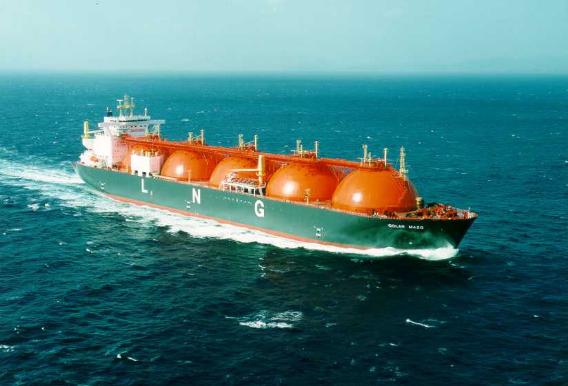
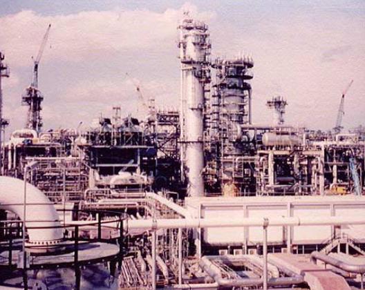
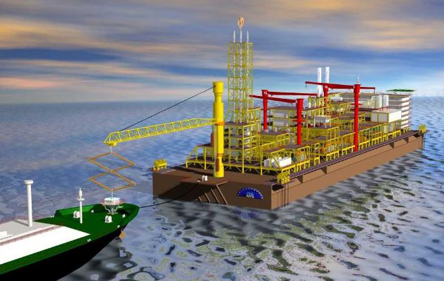
It brings together three established concepts in FPSO, Picture 1, with LNG Tanker, Picture 2 and LNG Plant, Picture 3.

What Has Been Done?
A number of proprietary and project specific designs plus two major Joint Industry Projects have been completed. A new EU project – SAFEOFFLOAD – is about to commence and these projects are discussed below.
GURF
The Gas Utilization Research Forum (GURF) is a non-profit organization whose mission is to provide a forum for the open exchange of ideas, and for the evaluation and formation of cooperative ventures to develop technologies targeted at economically challenged natural gas.
The Joint Industry Project for Large-Scale LNG FPSO was undertaken in 1998 the primary objective being the “Marinisation” of liquefaction processes and concepts. Two structural designs, one concrete and one steel; a concept-safety assessment; an evaluation of two different LNG processes; and an assessment of capital costs and construction schedules were completed. This included a draft design basis, concept safety assessment plan; LNG processes simulations and data generated; LSN process comparison; together with FPSO general arrangements. Bouygues and Ishikawajima-Harima Heavy Industries completed the vessel designs.
Participants included Amoco, BG, BP Exploration, Conoco, Chevron, Gaz de France, Shell, Statoil and PT VICO. Sponsors included Bouygues, Ishikawajima- Harima Heavy Industries, M. W. Kellogg and Paragon Engineering.
AZURE
AZURE R&D project for the development of floating Liquefied Natural Gas (LNG) facility concepts, it was performed with the support of the European Union’s Thermie program. The project addressed all technical issues in order to demonstrate that a fully floating LNG chain, from gas well to gas distribution network, is a safe and viable industrial proposal.
A consortium of nine European companies were part of the JIP including:
- M. W. Kellogg Ltd (MWKL);
- Chantiers de l’Atlantique;
- Fincantieri;
- FMC Europe;
- Gaz Transport & Technigaz (GTT; 30 % owned by Bouygues Offshore);
- Bureau Veritas (BV);
- Registro Italiano Navale (RINA);
- Institut de Recherches de la Construction Navale (IRCN).
Five international oil and gas companies gave their technical and financial support to the project:
- Shell;
- TotalFinaElf;
- Chevron;
- Texaco and;
- Conoco.
The 18-month work program called for designing floating liquefaction plants, floating LNG terminals and offshore LNG transfer systems. It included thorough testing of all the key components of the chain. The cryogenic storages involved are based on a membrane containment system, proposed by Technigaz and GTT.
For the liquefaction barge, two different scenarios were developed by MWKL. In South East Asia, a stand-alone gas field involving a 3 MMTPA capacity, based on a dual mixed refrigerant process cycle and in West Africa, a single processing train, involving a 1 MMTPA capacity with a nitrogen expander cycle for the liquefaction of the associated gas for a deep sea oil field.
Fincantieri developed the design for the floating receiving terminal located in Southern Europe, while the SN Technigaz regasification process was based on submerged combustion vaporizers with a LNG storage capacity of 200 000m3.
The transfer of LNG in open seas can be performed safely in a tandem-loading configuration, using the Boom-To-Tanker designed by FMC. A large-scale model of this device was successfully tested, using motion data from basin tests.
The project included both steel and concrete hull designs for the LNG FPSO. Chantiers de l’Atlantique developed the steel hull options, while Bouygues Offshore designed the concrete hull alternative.
Safety assessment of the various facilities of the floating LNG chain was performed under the supervision of BV and RINA. The necessary safety criteria can be met by combining current engineering practices from the offshore industry with those of onshore LNG terminals.
Advanced computer tools were developed by IRCN to address the liquid motion of the slack LNG storage tanks. It was found that sloshing was not an issue and this was confirmed by testing performed by GTT (liquid motion tests and impact testing on membranes).
Safeoffload
Noble Denton in association with a number of other European companies has recently completed an EU supported research project on Reliability Based Structural Design of FPSO Systems (REBASDO). A key objective of this project was to establish the effects on FPSO response as a result of using a more advanced description of the environment than is recommended currently in design codes for FPSOs. The effects of different energy spreading of wind-sea and swell have been investigated, as well as directional effects of the environment (i. e. wave spreading). Some of the results have been presented in a joint paper by DHI Water & Environment, Noble Denton and Instituto Superior Tecnico at the OMAE Speciality Conference on Integrity of FPSO Systems, 2004. Some important conclusions have been drawn which suggest that spread seas can worsen the loads on the vessel that hitherto assumed and that the steep wave effects can also be significant in the extreme design of FPSOs.
A new project has been awarded by the EU for a project entitled Safe Offloading from Floating LNG Platforms (SAFE OFFLOAD) that will assess the various components for safe offloading of LNG. The planned commencement date is January 2005. The participants will be Shell International Exploration and Production (The Netherlands), Instituto Superior Tecnico (Portugal), DHI Water & Environment (Denmark), Det Norske Veritas (Norway), Imperial College of Science, Technology & Medicine (UK), Noble Denton Europe Ltd. (UK), University of Oxford (UK) and IZAR FENE Shipyard (Spain).
The Basic Ship Motions and Mathematical Model used in Vessel Simulator (VeSim) Toolvessel motions that limit FLNG operations are excited by the environmental winds, waves and currents. If the weather windows that allow production and offloading are sufficient, the system has the potential to work safely and efficiently. The topics that this project addresses are the environmental conditions that influence the whole FLNG system, the interaction between the environment and the production and shuttle vessels, and the responses of the vessels during approach, offloading and disconnection. The vastly bigger size (>400 m length) of the FLNG platforms brings new global performance issues that have to be tackled so that a confident understanding of the behaviour of the FLNG can be gained. The ultimate goal of the project is to optimise the system to maximise operability and safety. The activities which the project will include are environmental modelling, numerical simulations, model tests and risk and availability assessments. By working together with leaders in each area of importance in FLNG offloading, the novel issues will be resolved confidently so that the complete system can be progressed effectively.
Proprietry and Project Specific Designs
A number of designs have been developed around specific tank concepts over the years. Both Technigaz and Moss have, in conjunction with various suppliers of LNG equipment, developed designs. These have tended to be generic designs without specific field development locations, however some have been field or at least geographical based.
FLNG Vessels
Hull
An FLNG hull can be built out of either steel or concrete. To date all LNG tankers have been constructed out of steel. There are today over 140 tankers operating, the first vessel that is still trading is the MV Cinderella that was built in 1965.
1 (a) Steel
A steel hull form has been developed by Shell for the Kudu and Sunrise developments. It is an extension of the existing trading tanker although on a much larger scale.

Floating LNG vessels have been based on the extension of the tanker designs. These tankers typically have a capacity of 130 000 cubic metres. This size is based on draft limitation at LNG receiving terminals most notably in Japan that typically have maximum operating draft of 11,5 metres.
As it now stands it is most probable that the first FLNG hull would be made of steel.
1 (b) Concrete
There are a number of large existing concrete vessels in the world most notably:
- Elf N’kossa barge built by Bouygues in 1996;
- Conoco Heidrun Tension Leg Platform, 288 200 tonnes displacement, installed in 1995;
- Norske Shell Troll Olje Semi-Submersible, 193,700 tonne displacement, installed in 1995;
- ARCO Ardjuna LPG storage barge, 60 000 tonne deadweight vessel installed in 1975.
There have been a number of proposals made for the use of concrete for FLNG. Both the Azure and Gurf JIP’s had concrete options. In fact Shell were originally looking at Concrete for the Kudu and Sunrise projects as stated in 2002 OTC paper number 14100.
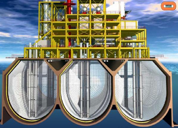
Concrete was thought to be better suited to floating LNG as it could provide additional protection, improved insulation and higher resistance to any deck spills. However initial concrete designs developed for AZUR, Fig 4.2, indicated that some form of heating may be required. The steel reinforcement is prone to fracture at extreme temperatures.
There is also the possible ingress of water through the concrete and the possibility of it freezing would have to be further investigated. This is particularly relevant to Cargo Containment Systems of LPG and LNGmembrane containment systems as the structure is directly next to the concrete hull. For self-supporting systems, such as IHI and Moss, the gap afforded by the cofferdam allows greater possibility of this water ingress not giving problems.
In summary the concrete hull has a number of challenges that require solving before it can be accepted for use on a Floating LNG project.
Containment Systems
The merits of the various containment systems for use in FLNG are stated as follows.
2 (a) Moss Spherical
Moss claim and Statoil has funded studies into using these tanks on FLNG. Due to the large amount of the tank on protruding over the main deck no process equipment can be placed there. Separate process areas would be required and the type and size of this equipment would determine if this could be efficiently accommodated.
As the tanks can be built in parallel to the hull they could have schedule advantages as tank and hull fabrication could coincide and the vessel would be available for transportation to topsides integration facility.
2 (b) IHI Prismatic
Although having limited number of applications for LNG although some more for LPG these tanks do have potential befits for FLNG.
As the tanks can be built in parallel to the hull they could have schedule advantages as tank and hull fabrication could coincide and the vessel would be available for transportation to topsides integration facility.
2 (c) Technigaz Membrane
These tanks are now being used on a frequent basis for LNG Tankers. Typically the steel Hull is built with suitable staging in the tanks, the ship is then launched and the insulation put in place with the tanker alongside. For FLNG this could prolong the schedule, as the vessel would not be available for transport to topsides integration facility until all insulation had been placed. An alternative would be to place topsides at the same time as the insulation is placed, this would be possible if the topside integration and hull fabrication took place at the same location.
Fabrication
Fabrication of the complete FLNG does in itself offer a number of challenges. The proposed size of the unit with relatively high freeboard has led to some “blue sky thinking” as to how best to put the LNG plant weighing over 40 000 tonnes on the deck that will be 30 metres above the quay. The possible methods were described by Orscar FR. Graff of Aker Kavaerner Technology in a paper given at the IBC FPS 2003 conference.
Tank selection can also greatly influence the build sequence and overall schedule.
Offloading
The transfer of LNG to a tanker is one of the major challenges of FLNG development.
A number of operators and contractors have recognised the need for a safe and reliable system of transferring LNG from a floating to production tanker to an offtake LNG tanker.
For more benign waters side by side loading can be undertaken and this was proposed for Sunrise. This is an extension on the existing technology specifically developed for the loading/offloading of LNG trading tankers.
For the relatively more stormy waters such as Kudu side by side off loading would impact the vessel operations as there would be considerable periods when the vessel could not off load. For these conditions a tandem system is required. The principal is similar to that widely used for oil offtake on FPSO’s with the offtake tanker astern of the production vessel. It does require the offtake tanker to have the appropriate receiving equipment fitted. Typical operating sea-states for tandem offloading are for connection 3,5 metre significant wave height and for remaining connected 5,0 metres significant.
For tandem offloading of LNG there would appear to be two distinct configurations that are:
Hard connection
Rigid pipe connection, differentials in movement accounted for by swivels and hard connections. Bluewater, SBM and FMC have developed these.
Soft connection
Flexible pipes are used in at least part of the system to account for this differential movement. Framo and Coflexip have developed these.
Much work still has to be completed before a proven offloading system can be used.
4 (a) Proposed Systems
A number of systems are being developed by various companies, the following list is what is known to the author at time of writing and there may well be other suitable systems.
4 (b) Offloading systems
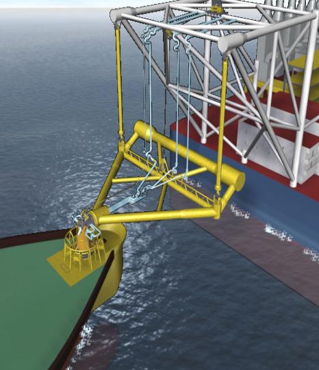
SBM have developed a system called SYMO, Soft Yoke Mooring and Offloading, a full description was given by Poldervaart and Mahood at the 18th IBC FPSO Conference in London in December 2003 and is shown in Picture 7.
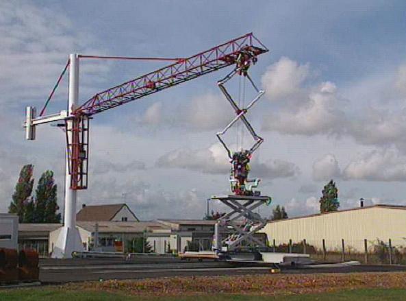
FMC, as part of the AZUR project Ref 2 developed a pantograph type system, as part of the project a 1/5 scale model was tested and this is shown in Picture 8.
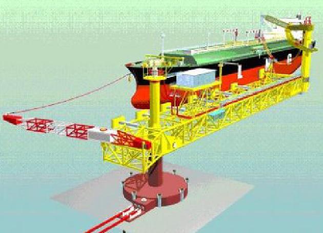
Bluewater has developed a system aimed of the receiving terminal end of operations although they do claim it can be adapted for FLNG use. Picture 9 shows arrangement.
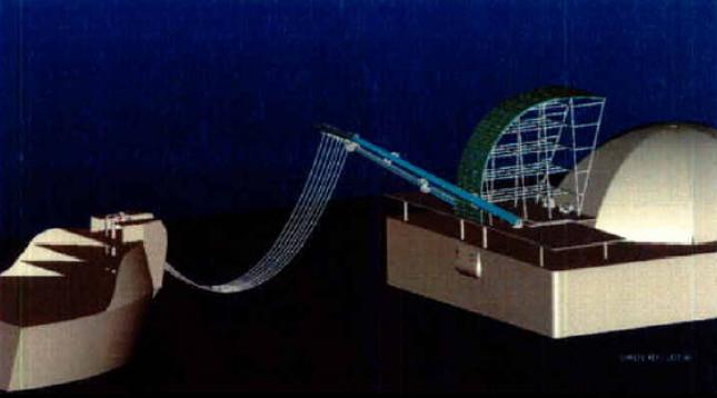
OCL/Framo developed in conjunction with Statoil a soft connection system. Picture 10 shows arrangement:
Conclusion
For FLNG developments to take place a viable development scenario has to exist that makes economic sense. Following the cancellation of Kudu and the continued deferral of Sunrise there does not appear to be any genuine prospects in the pipeline.
Most stranded gas developments, as witnessed by the probable Angolan offshore developments, have opted for the pipeline to land and the full blown onshore LNG plant.
FLNG still has a number of technical stage gates to complete and there may well be some items that have not yet been uncovered, a saying of the KBR Team FLNG was “We don’t know what we don’t know”.
Despite this the author is optimistic that with the apparent constant demand for gas and the ban on flaring there is a development somewhere in the world that will take the technology already completed and go forward with this technologically challenging development.