The gas handling equipment for industrial applications is designed to provide safe and efficient processing, storage and distribution of gases in various industrial settings. By utilizing the latest technologies and solutions, industries can optimize their gas handling operations and improve overall productivity, safety and environmental sustainability
Innovative gas handling solutions are designed to comply with stringent safety standards, providing industries with reliable tools to manage and control gas emissions effectively.
Relief Valves
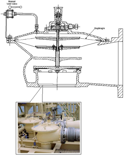
Cargo Tank Relief Valves
The followings are typical characteristics of General Overview of LNG Cargo Tanks (Typical Operations)cargo tank relief valves for a LNG carrier of 138 000 m3 capacity. These characteristics may be considered indicative for ships with capacity ranging between 135 000 and 150 000 m3.
| Table 1. The Following Characteristics of Cargo Tank Relief Valves for a LNG Carrier | |
|---|---|
| CHARACTERISTIC | 135 000-150 000 m3 LNGC |
| Typical number of units | 2 per tank plus 1 spare |
| Overpressure | 25 kPa gauge |
| Flow rate per valve | 24 538 Nm3/h |
| Vacuum relieving | 1 kPa gauge |
| Flow rate per valve | 4 302 Nm3/h |
Figure 1 is a typical cargo tank relief valve.
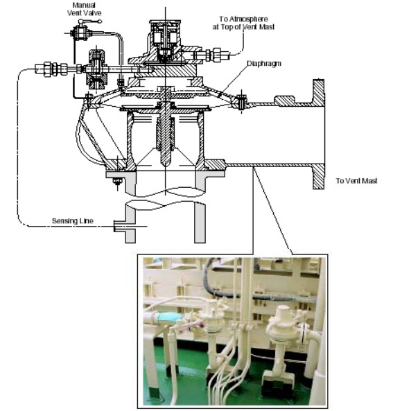
Interbarrier Spaces Relief Valves
The followings are typical characteristics of Interbarrier Space Protection: Pressurization, Inertization and Scaffolding Techniquesinterbarrier space relief valves for a LNG carrier of 138 000 m3 capacity. These characteristics may be considered indicative for ships with capacity ranging between 135 000 and 150 000 m3.
| Table 2. The Following Characteristics of Interbarrier Space Relief Valves for a LNG Carrier | |
|---|---|
| CHARACTERISTIC | 135 000-150 000 m3 LNGC |
| Typical number of units | 16 plus 1 spare |
| Number per tank – Secondary barrier space | 2 |
| Number per tank – Primary barrier space | 2 |
| Overpressure – Secondary barrier | 3,0 kPa gauge |
| Overpressure – Primary barrier | 3,5 kPa gauge |
| Flow rate per valve – Secondary barrier | 289 Nm3/h |
| Flow rate per valve – Primary barrier | 318 Nm3/h |
Figure 2 is a typical interbarrier tank relief valve.
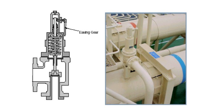
Line Relief Valves
In general the line relief valves are set at: 1 000 kPa gauge. Figure 6 is a typical line relief valve.
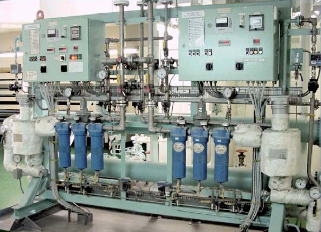
Nitrogen Generators
High Capacity Units
Nitrogen generator has the following components installed:
- a high capacity units water-cooled screw compressor;
- a single stage air/water separator;
- three air filters arranged in series;
- an electric heater.
After passing through the membrane units an oxygen analyzer monitors the oxygen content. The nitrogen generated is stored in buffer tanks, where high and low service pressure set points actuate the start and stopping of the generators.
Main Characteristics
The main characteristics of nitrogen generators typically installed on board an LNG carrier of 138 000 m3 capacity are given in the following table. These characteristics may be considered indicative for ships with capacity ranging between 135 000 and 150 000 m3.
| Table 3. The main Characteristics of Nitrogen Generators Typically on Board a LNG Carrier | |
|---|---|
| CHARACTERISTIC | 135 000-150 000 m3 LNGC |
| GENERATOR | |
| Nominal flow rate | 90 Nm3/h + 90 Nm3/h at 97 % N2 |
| Delivery pressure | 8 bar |
| Dew point | -70 °C |
| Outlet gas composition | Oxygen 3 % by volume |
| Carbon dioxide | < 30 ppm |
| Nitrogen balance | to 100 % |
| HOLLOW FIBER MEMBRANE UNIT WITH DRY FILTERS | |
| Capacity (at 50 °C inlet temperature) | 90 + 90 Nm3/h |
| N2 content | 97 % |
| O2 residual | 3 % |
| BUFFER TANK | |
| Capacity | 24 m3 |
| ELECTRIC HEATER | |
| Power | 4 kW |
| SCREW COMPRESSOR | |
| Capacity | 306 m3/h |
| Compressed air at membrane inlet | < 125 kPa |
| Maximum back pressure O2 enriched air | 0,05 kPa |
| Nominal power | 52 kW |
| System operating temperature range | 0 to 35 °C |
| Membrane inlet operating temperature | +50 °C |
| Oil residual content | < 0,003 ppm |
| Filtration efficiency for particles with size 0,01 micron | > 99,99 % |
| Dew point | -20 °C(1) |
| Independent time operated condensate time operated | 4 |
| (1) with drying capability of membranes, final dew point will be < -55 °C | |
Membranes are provided with a back-pressure control valve downstream of a flow meter, which maintains constant membrane pressure.
Generators are further equipped with an oxygen analyzer, which continually monitors the oxygen content in the output. If the oxygen level rises above 1 % of the design value, then an alarm is activated on the console. If the level of oxygen rises further then the high-high alarm operates, redirecting the flow to atmosphere and closing the discharge line to the buffer tank.
The gaseous Nitrogen Generator System on Liquefied Natural Gas Carriersnitrogen generators are operated automatically, locally or from the CACC by the IAS mimic.
Figure 4 shows a nitrogen control panel and filters in engine room.
Control System
The control panel permits fully automated operation of the units. The following alarms and controls are mounted on the panels.
- Pushbuttons for start/stop operation.
- System status indications.
- Pushbutton for audible alarm acknowledgement.
- Continuous N2 delivery pressure.
- Continuous O2 content reading.
- Dew point analyzer.
- Electrical heater temperature control.
- Emergency stop pushbotton.
Inert Gas Generator
General
Figure 5 shows the plant relative to the generation of the inert gas. In principlethere are no significant differences between an inert gas generator for an oil tanker or a chemical carrier and the one for a LNGC.

Burners
The combustion air is supplied to the main burner by two “roots” type blowers, each supplying 50 % of the total capacity of the generator. The quantity of combustion air to the burner can be manually adjusted by a regulating valve in the excess air discharge line.
The low sulphur diesel oil is supplied at a constant pressure by the fuel pump, which has a built-in pressure overflow valve.
Before ignition or start up of the unit and with the pump running, all the fuel is pumped back via this fuel overflow valve, which also serves to regulate the delivery pressure of the pump. The fuel flows to the nozzle of the main burner via two solenoid valves and two fuel regulating valves.
A program switch in the local control panel regulates one of the solenoid valves, which also operates the pilot burner and initial firing.
The main burner is lit by an igniter. The main fuel burner is of the high pressure atomizing type. The fuel is directed to the burner orifice through tangential slots, which imparts a rotary motion ensuring that the fuel leaves the burner as a thin swirling cone, which is atomized just after the nozzle.
Miscellaneous Equipment
Filter
LNG may contain debris, therefore, since all rotating equipment operate to small clearances, adequate filters are to be arranged at the cross over connections, suction of compressors, heaters, etc.
Pipes, Valves and Fittings
a) CARGO AND PROCESS PIPING
The cargo piping is exposed at temperature variations from less than minus 160 °C, when LNG is loaded to plus 80 °C during warm-up. Consequentely, Piping System of pressure vessels on gas tankersthe piping system is subject to the following loads:
- Thermal loads due to temperature variations.
- Loads induced by the movement of the vessel (hogging and sagging).
- Loads induced by the piping system restraints.
- Internal pressure.
Loads induced by green-seas (contemplated by other Classification Societies) do not appear very probable due to the high freeboard of the LNGC.
Piping system computerized analysis is therefore essential for the dimensioning of the cargo and process piping. ABS has the software facilities to perform such analysis either for design or verification purposes.
LNG terminals endeavor to receive discharge as to load vessels as rapidly as possible within safety limits. To facilitate this, LNGC’s are designed and constructed with relatively large cargo piping on deck. It is not uncommon to have 600/700 diameter mm cargo lines. As these lines are SUS 304 or 316L, the schedule is relatively low (generally schedule 10) considering the strength of material and service pressure, extreme care must be exercised in the fit-up and weld of these pipes and fittings to avoid “hard points“, which may cause problems after several thermal cycles.
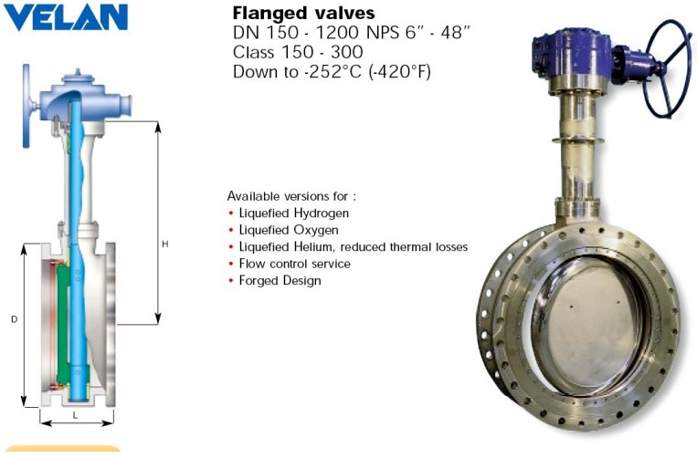
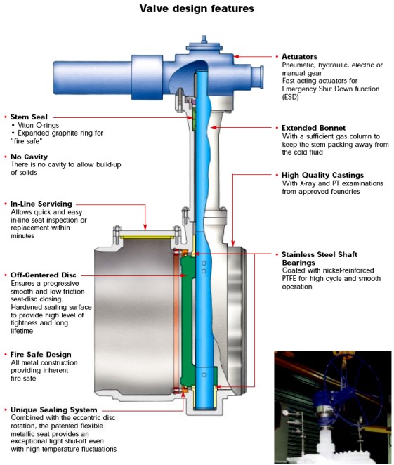
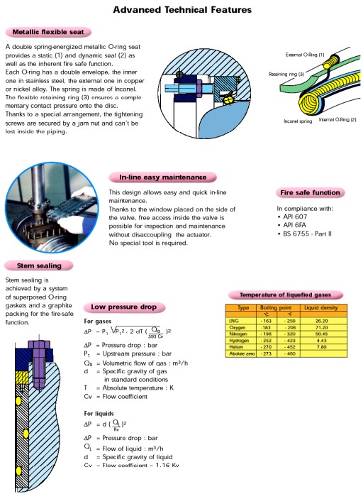
b) VALVES AND FITTINGS
Valves and fittings are to be type tested under simulated operation conditions that they will encounter in service. Particular care is to be paid to the remote control hydraulic or pneumatic actuator media due to the very low temperature at, which they can be exposed. In general the valves used in the cargo and process lines are globe or gate valves with metal to metal seats. Other type of valves may be used, provided they may assure the same effectiveness in the various service conditions.
The type approval test of the cryogenic valves (valves for temperatures below –55 °C consists in a tightness test to the minimum design temperature, or lower at a pressure not lower than the design pressure of the valve. During the test, satisfactory operation of the valve is checked.
Figures 6, 7 and 8 show a typical cryogenic valve and its main characteristics.
c) EXPANSION BELLOWS
Each type of expansion bellows is to be type approved. Type approval test is to include:
- Pressure test up to 5 times the design pressure for at least 5 minutes without bursting. The test is to be performed at the extreme displacement condition and, if specially requested depending on the material at the minimum design temperature.
- A cyclic test (thermal movement) for at least the same number of cycles the bellows is supposed to withstand during its life at all contemplated condition of pressure, temperature and movement.
- A cyclic fatigue test for 2 000 000 of cycles at a frequency not higher than 5 cycles/seconds.
Some of these tests may be waived to the Administration satisfaction.
Cryogenic Cargo Hoses
Cryogenic hoses are to be prototype tested under their extreme design conditions. The tested prototypes cannot be used on board. Hoses are to be hydrotested to 1,5 times their design pressure. Prototype test of cryogenic hoses is a severe issue.