The natural gas liquefaction process is the key component in LNG plants in terms of cost, complexity, and operational importance. A good understanding of design and operational requirements and effi-ciencies of natural gas liquefaction systems is essential for the success of the gas liquefaction plant. There are several licensed natural gas liquefaction processes available with varying degrees of com-plexities and experience. The thermal efficiency and capital cost for the various licensed processes are competitive and the differences are typically small with respect to thermodynamics and cost. The real keys in developing a successful liquefaction plant are equipment selection and its configurations to meet a plant’s capacity goals.
Introduction
This chapter provides a critical overview of the process technology options available for the liquefaction of natural gas, and discusses the factors that should be considered by project developers in order to select the most appropriate process for their situation.
Natural gas liquefaction technology
Liquefaction background
Liquefaction technologies are based on refrigeration cycles, which take warm, pretreated feed gas and cools and condenses it to cryogenic temperatures into a liquid product. The refrigerant may be part of the natural gas feed (open-cycle process) or a separate fluid continuously recirculated through the liquefier or heat exchanger (closed-cycle process). To achieve the extremely cold or cryogenic tem-peratures required to produce LNG, work must be put into the refrigerant cycle(s) through a refrigerant compressor(s), and heat must be rejected from the cycle(s) through air or water coolers. A number of natural gas liquefaction processes have been developed over the last five decades based upon this fundamental principle.
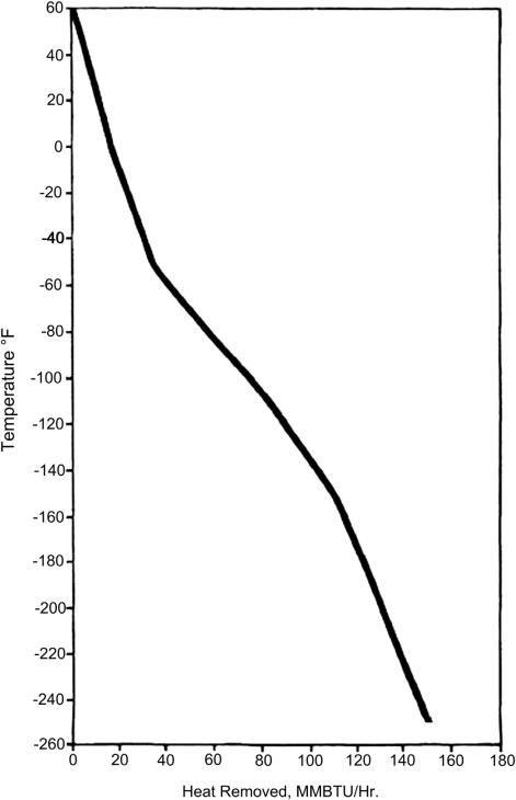
Besides seeking to reduce unit investment and operating costs, the primary objectives of these technological innovations are to increase the volume of Environmental aspects in Liquefied Natural Gas productionLNG production gas and optimize the efficiency of the refrigeration process employed. In theory, the most thermodynamically efficient liquefaction process is one with a refrigerant or a mixed refrigerant system that can duplicate the shape of the natural gas cooling curve at operating pressure (see Figure 1). Observing the cooling curve of a typical natural gas liquefaction process, three zones can be noted in the process of the gas being liquefied. A precooling zone, followed by a liquefaction zone, and completed by a subcooling zone. All of these zones are characterized by having different curve slopes, or specific heats, along the process.
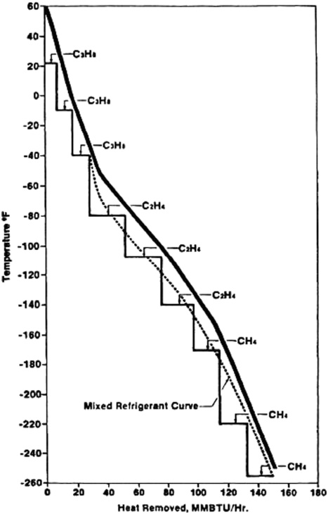
The duty curve associated with a specific gas liquefaction process can be used as a design opti-mization tool. In such an approach the key liquefaction equipment components are designed to match as closely as possible the cooling curve of the gas being liquefied at the different zones/stages of the liquefaction process in order to achieve high refrigeration efficiency and to reduce energy consumption. Figure 2 illustrates the cooling curves for a natural gas system, and the heating curves for a propane-precooled/mixed (C3-MR) refrigerant system and a three-refrigerant classical cascade refrigerant system. Another mixed refrigerant in some plant designs is substituted for the propane in the process shown in Figure 2. Thermodynamically, the mixed refrigerant comes closest to a reversible process because it minimizes the temperature difference between the two fluids (i.e., the gas being cooled and the refrigerant being heated in the heat exchange process). The smaller the temperature difference between the process gas and refrigerant, the more heat exchange area is required for the duty. Therefore, LNG process design is an exercise of optimization among refrigerant selection and composition, heat exchanger design and heat transfer area, and matching the refrigerant power consumption to available compressor/driver capacity. The classical cascade liquefaction process attempts to approximate the cooling curve by use of a series of refrigerants (usually three) in separate loops. Use of more than three refrigerants allows a closer approximation to the cooling curve but with the penalty of additional equipment, higher cycle complexity, and higher operating costs and larger plant footprint.
The differences between gas liquefaction processes are mainly associated with the type of refrigeration cycles employed. These processes can be broadly classified into three groups: cascade liquefaction processes, mixed refrigerant processes, and expansion-based processes.
Cascade cycle
The classical cascade process reduces the irreversible heat exchange losses by utilizing several refrigeration cycles whose refrigerants vaporize at different but constant temperatures. The cascade cycle is flexible in operation, since each refrigerant circuit can be controlled separately. The cascade cycle has a comparatively low heat exchanger surface area requirement per unit of capacity. Economics of scale show that the cascade cycle is most suited to large train capacities, since the low heat exchanger area and low power requirement offset the cost of having multiple machines. The other advantages are low technical risks and the utilization of standard equipment resulting in reducing the construction period. However, the disadvantages of the cascade technology are the relatively high capital investments, insufficient flexibility/adaptation to variations in natural gas composition, and production train capacity limitations. There are two modifications of the classic cascade process utilized in operating gas liquefaction plants: the optimized cascade (developed by Conoco-Phillips) and the mixed-fluid cascade (elaborated by Linde and Statoil).
Mixed refrigerant cycles
The mixed refrigerant (MR) cycle involves the continuous cooling of a natural gas stream using a carefully selected blend of refrigerants (usually a mixture of light hydrocarbons and nitrogen) that can mimic the cooling curve of natural gas from ambient to cryogenic temperatures, so that energy usage and heat exchangers size can be optimized.
When compared to the cascade technology process, the advantages of the mixed refrigerant process are better proximity to operational temperature of heat exchangers; lower number of compressors and heat exchanger services; and its ability to adjust refrigerant compositions to accommodate the changes in gas composition, feed gas throughput, and plant operating pressure. On the other hand, a single MR cycle typically has a lower thermal efficiency than the more complex cascade cycle because a single mixed refrigerant composition just cannot optimally match the wide range of cooling temperatures in the liquefaction of natural gas. The refrigeration process also takes longer to start up and line up because of the need for precise blending of the refrigerant mix. This is a significant consideration in an environment where frequent start-up and shutdown are to be expected that would require frequent adjustment of the refrigerant composition. The MR concept has been applied in several liquefaction plant designs.
Single mixed refrigerant cycle
The single mixed refrigerant (SMR) process involves an inverse or reverse Rankine cycle, in which the gas is chilled and liquefied in a single heat exchanger. The Rankine cycle generally refers to a cycle that converts heat into work, using a working fluid such as steam or hydrocarbons. The reverse Rankine cycle uses power to generate cooling by rejection of heat, and in the case of Cargo Tank Instrumentation on Gas Tankers
LNG plant, propane or a mixed refrigerant can be used as the working fluid.
The mixed refrigerant is a mixture of several compounds (mainly hydrocarbon with low boiling points and nitrogen), and the optimum composition is determined by the feed composition, feed pres-sure, liquefaction plant pressure, and ambient temperature. The refrigeration process follows a reverse Rankine cycle in the following stages: compression-cooling-condensation-expansion-evaporation. Cooling of the refrigerant occurs at ambient temperature whereas evaporation of the refrigerant occurs at a low temperature that is used for liquefaction. Due to its relatively low thermal efficiency, the single mixed refrigerant cycle is mainly suited to mid-sized and small-scale plants where low cost and simplicity are the deciding factor in the plant economics.
Dual mixed refrigerant cycle
The dual mixed refrigerant (DMR) process achieves the liquefaction of the feed gas using two in-dependent MR cycles. In the first cycle the natural gas is precooled by a heavier mixed refrigerant. Subsequently the cooled natural gas is condensed in a second heat exchanger by a lighter mixed refrigerant. The heat exchangers are commonly half the height and size of the heat exchangers used in a single mixed refrigerant (SMR) process due to the split of the cooling duty into two cycles.
Numerous versions of the dual-stage cooling cycles with one or both cycles involving mixed re-frigerants have been developed. The propane precooled mixed refrigerant process (C3-MR) is the most widely used (i.e., the first cycle employing a single propane refrigerant and the second cycle a mixed refrigerant). The C3-MR cycle uses a closed loop propane refrigeration circuit to precool the natural gas stream. The balance of the liquefaction process uses a mixed refrigerant (MR). The precooled process results in a more efficient plant design and uses less power when compared to SMR systems. The downside of this modification is the higher process complexity and the higher processing equipment counts.
Gas expander cycles
The expansion-based gas liquefaction processes utilize turbo-expanders to produce the refrigerant for liquefaction. The turbo-expander refrigeration cycle works by compressing and expanding a fluid to generate refrigeration. The expansion cycle has been greatly improved due to the advances in high efficiency turbo-expanders (typically over 85 %).
The process can be configured as single, dual, or multiple turbo-expander designs that can be driven by electric motors or gas engines. The heat curves of expander liquefaction processes have a relatively large temperature gap between refrigerant and cooling gas, typically at the warm end of the natural gas cooling curve. The refrigerant, either nitrogen or methane, is a light volatile component that is a better refrigerant for low temperature cooling rather than the high temperature range in the beginning of the gas cooling, especially when the feed gas contains significant amounts of C3+ components.
The refrigerants remain in the gaseous state throughout the expansion cycles. Being a single component, there is no need to adjust the composition, thus simplifying the process operation. Also, because the heat exchangers operate with relatively wide temperature approaches, they are less sensitive to changes in feed gas compositions. For these reasons precise temperature control is not as critical as it is for mixed-refrigerant cycles. This cycle is considered to be more stable over a range of liquefaction conditions. Nevertheless, the expander cycle is less efficient when compared to the cascade and mixed refrigerant cycles (see Table 1), which makes it suitable for small LNG plants (such as BOG liquefaction) and less suitable for large-scale base load plants.
Nitrogen expander cycle efficiency can be improved to some extent with additional equipment, such as multiple expanders and the use of propane precooling but are seldom justified for small plants. However, because there is no hydrocarbon liquid inventory, the design is inherently safe. Being a gas phase cycle, the system performance is not much impacted by ship motion and is more suitable for ship-based floating liquefaction plants.
Liquefaction process selection criteria
LNG process selection has often been highly influenced by the specific power consumption, (i.e., kW/ton of LNG). This is certainly an important parameter, since refrigerant compressors are the single largest cost and energy consumption components in a gas liquefaction train. However, in order to compare different natural gas liquefaction systems, it is necessary to compare (1) the compressor power required, (2) the heat exchanger surface area requirement, and (3) and the temperature approaches between the heating and cooling curves in the main cryogenic heat exchanger.
The cooling performance curve is a benchmark that is commonly used in LNG technology com-parison. However, it can be misleading if energy performance of a liquefaction system is the only consideration without taking life-cycle costs into account. A detailed knowledge of the design and operation, and the capital and operating cost of the liquefaction process is necessary to make a meaningful comparison.
The first few natural gas liquefaction plants and a few current plants were based on the classical cascade processes operating with pure components such as methane, ethylene, and propane. The majority of existing base-load natural gas liquefaction plants operate with at least one mixed refrigerant cycle. However, other processes such as the cascade system operating with mixed refrigerants and dual mixed refrigerant processes have been built in recent years (e.g., Sakhalin in Russia and Snohvit in Norway). Expander-based cycles that operate with nitrogen as the working fluid are used in a number of small-scale gas liquefaction plants, peak shaving plants, and the BOG recovery units, such as the BOG reliquefaction systems in Q-Max LNG ships.
Suggested reading: Liquefied Natural Gas Projects, calculation of the cost of gas production
In the following section, the most commonly licensed processes utilizing one and/or combinations of the previously mentioned technologies are discussed in more detail.
Onshore natural gas liquefaction processes
The most common onshore gas liquefaction technologies are described next. These processes have been successfully applied to land base liquefaction plants. The descriptions do not attempt to disclose the full details of the licensor processes, but rather the basic design concepts and design considerations. The liquefaction processes are continuously evolving, and there are many versions of the same licensed processes that take advantage of current equipment advancement. Involving mainly gas turbine drivers and heat exchanger designs, in most cases the new versions are design enhancements built upon the original design concepts.
APCI propane precooled mixed refrigerant process
The Propane Precooled Mixed Refrigerant (C3-MR) process, developed by Air Products & Chemicals Inc. (APCI), is the most widely used liquefaction process to date. This process has dominated the base load LNG technology since the late 1970s with about 75 % of the natural gas liquefaction market.
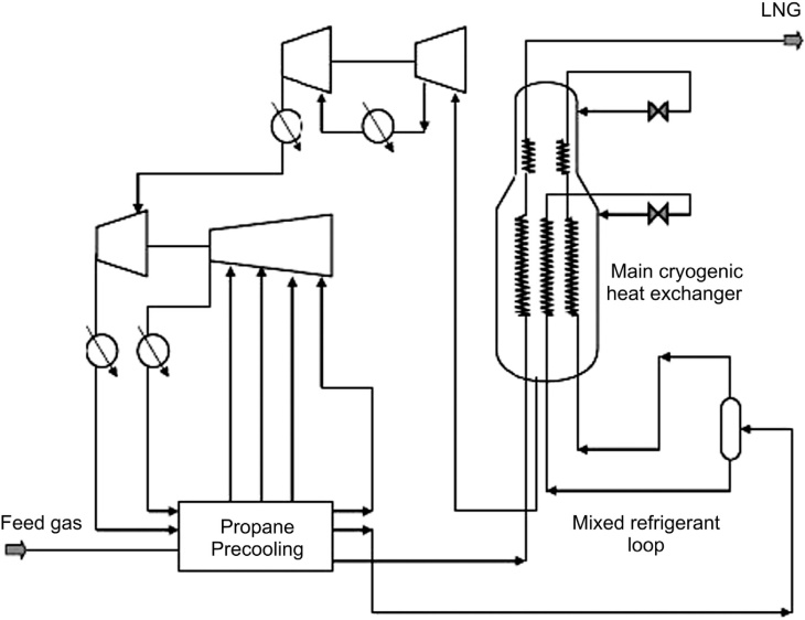
The C3-MR process, as shown in Figure 3, is composed of a multistage propane precooling system followed by liquefaction using a mixed refrigerant system (made up of nitrogen, methane, ethane, and propane). The natural gas feed is initially cooled by a separate propane chiller package to an intermediate temperature, approximately -35 °C (-31 °F). The natural gas is then liquefied and subcooled in the main cryogenic heat exchanger (MCHE), composed of a large number of small-diameter spiral-wound tube bundles (i.e., spiral-wound or spool-wound heat exchanger). The mixed refrigerant is partially condensed by the propane chiller before entering the heat exchanger. The separate liquid and vapor streams are then chilled further before being flashed across Joule-Thomson valves, which provide the cooling for the final gas liquefaction.
The heart of the APCI C3-MR process is its proprietary spiral wound heat exchangers (SWHE). Large capacity trains over 5 MTPA can be designed using the split MR compressor/driver arrangement, where the available power of each gas turbine driver and its helper motor/turbine is fully utilized for LNG production with a minimum number of refrigerant compressor casings.
A modification by APCI made in the past decade has increased the size of LNG plants (over 6 MTPA; e.g., several liquefaction trains commissioned in Qatar 2008 to 2011 are over 7.8 MTPA). The AP-X™ process adds a third refrigerant cycle (nitrogen expander) to provide the LNG subcooling duties outside the main cryogenic heat exchanger –MCHE. With the nitrogen cycle, the size of the main exchanger can be kept the same, with the subcooling duty shared by the nitrogen cycle. This design approach makes liquefaction of 10 MTPA possible without development of a larger main exchanger. More details on the AP-X process are discussed in Chapter 10.
Phillips optimized cascade LNG process
Phillips Petroleum Company developed the original cascade LNG process in the 1960s. This process was first used in 1969 at the ConocoPhillips’ Kenai LNG plant in Alaska. Figure 4 provides a design schematic of a typical Phillips Optimized Cascade Liquefaction Process (POCLP). This process uses propane and ethylene systems and a multiple stage Cargo Temperature Control and Cargo Vent Systemsmethane refrigeration system to balance refrig-eration loads.
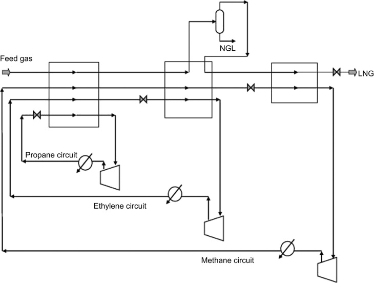
In this process, feed gas is routed successively through each stage of propane and ethylene chillers. Air or cooling water removes the compression heat and condenses propane, while propane removes heat and condenses ethylene. Heavier components (NGL) typically are removed from the feed gas after one or more stages of chilling and the resulting methane-rich feed is routed through the methane refrigeration system. If methane refrigerant contains nitrogen, a slip stream is drawn off to be used as fuel to prevent build-up of inert. LNG from the last stage flash drum is sent to the LNG tanks by the LNG transfer pumps where it is stored at approximately 70 mbar above atmospheric pressure and at-161 °C.
Each refrigeration circuit uses two 50 % compressors with common process equipment. Brazed aluminum heat exchangers and core-in-kettle heat exchangers can be used for the refrigeration circuits. These exchangers are open arts designs that can be supplied by several manufacturers. The heat exchanger designs are less complex than the proprietary spiral-wound heat exchanges used in the C3-MR process.
Train sizes of liquefaction plants built to date with POCLP technology are less than 5.0 MTPA but the process is claimed to be capable of larger train sizes. The POCLP is claimed to be able to provide designs with high thermal efficiency (exceeding 93 %). Design thermal efficiencies for the optimized cascade facilities commissioned at Darwin Australia in 2006 were reported to range from 90 to 93 % and could reach 94 % in some cases. Turndown rates to 10 % are also claimed.
Phillips and Bechtel have entered into a global collaboration providing design, construction, commissioning, and startup for the POCLP plants. The most recent plant of this design to come onstream is the Soyo plant operated by Chevron in Angola (2012). The Phillips/Bechtel alliance provides a single contractor working with a technology licensor to be responsible for the process performance and project execution, which lowers the operation and financial risk on large projects. The avoidance of joint venture EPC contractors has significant benefits to the financial institutions when financing grass-root liquefaction plants.
Black & Veatch Pritchard PRICO® process
Black & Veatch Pritchard has developed a proprietary mixed refrigerant process, PRICO®, which has been successfully used in both base load and peak shaving applications. The basic configuration is shown in Figure 5. The mixed refrigerant is made up of nitrogen, methane, ethane, propane and iso-pentane. The component ratio of this refrigerant is chosen to closely match its boiling curve with the cooling curve of the natural gas feed.
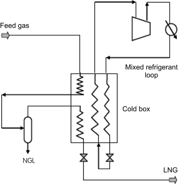
The mixed refrigerant (MR) is compressed and partially condensed prior to entering the cold box. The mixed refrigerant is totally condensed in the cold box and is flashed across an expansion valve, which causes a further drop in temperature. This vaporizing liquid then provides the chilling duty for condensing the natural gas feed. The low-pressure MR vapor is then recompressed by the refrigeration compressor and the cycle is repeated. In the PRICO® process, the natural gas feed stream is first cooled to about -35 °C (-31 °F), which condenses most of the heavy hydrocarbons to avoid freezing in the cold section. The condensed hydrocarbon is further fractionated into individual products. The residual gas is then further cooled and condensed in the cold box.
The PRICO refrigeration system is simple and the number of equipment counts is lower than the propane precooled MR or cascade processes. However, this process is not as efficient as the multiple-cycle processes and is therefore not suited for large base load LNG plants. The PRICO process is mainly reserved for smaller-scale or peak shaving LNG plant applications. The Black & Veatch PRICO liquefaction process was recently used in China for peak shaving and vehicle fuel applications because of its simple operation, low capital and operating costs, and its flexibility in handling a wide range of feed gas compositions.
Statoil/Linde mixed fluid cascade process
The Statoil/Linde LNG technology alliance was established to develop alternative LNG base load plants particularly suitable for harsher environments. It was pioneered in the Snohvit plant deployed on Melkoya Island offshore Hammerfest in the Northern North Sea (i.e., latitude 71° North) of Norway. This plant remains Europe’s only base load export gas liquefaction plant.
The technology incorporates the Mixed Fluid Cascade (MFC) process. The MFC process is a classic cascade process with the difference that the mixed components refrigerant cycles replace single component refrigerant cycles, thereby potentially improving the thermodynamic efficiency and operational flexibility.
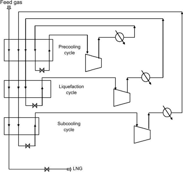
As shown in Figure 6, the MFC process takes purified natural gas and precools, liquefies, and subcools it by means of three separate mixed refrigerant cycles. The precooling cycle involves two plate fin heat exchangers (PFHEs), whereas the liquefaction and subcooling cycles utilize two spiral-wound heat exchangers. The SWHE could also be used for the precooling stage. The refrigerants are made up of components selected from methane, ethane, propane, and nitrogen. The three refrigerant compression systems can have separate drivers or be integrated to have just two strings of compression. Frame 6 and Frame 7 gas turbine drivers are used in the large liquefaction trains (> 4 MTPA).
To date, only one gas liquefaction plant has been built using the MFC process. The Snohvit plant was built by Aker in a joint venture with Linde and has a capacity of 4.3 MTPA. However, since commissioning in 2007 (more than one year behind schedule and significantly over budget) the plant has experienced poor operating performance. In particular, reportedly heat exchangers are not per-forming and require replacement.
IFP/Axens Liquefiin™ process
IFP and Axens proposed the Liquefin™ liquefaction process, aimed at achieving high capacities with simple equipment configurations and standard compressors. It is a two-mixed refrigerant process as illustrated in Figure 7.
Feed gas enters the liquefaction train’s precooling section where it is cooled between -50 °C and -80 °C (-60 °F and -110 °F) using a mixed refrigerant in a bank of brazed aluminum plate-fin heat exchangers (PFHEs). The cooled feed gas stream is separated for NGL removal. The gas returns to the heat exchanger and enters the cryogenic section where it is liquefied with a second mixed refrigerant.
The first mixed refrigerant is used at three different pressure levels to precool the process gas and the second mixed refrigerant is used to liquefy and subcool the process gas. The mixed refrigerant gas entering the precooling section is completely condensed by the time it leaves the cryogenic section. After leaving the cryogenic section, the refrigerant is expanded and reenters the cryogenic section where the process gas and refrigerant are condensed.
This process involves shifting a good part of the condensation duty from the cryogenic section to the prerefrigeration cycle. Theoretically, this shifting of duty provides opportunity for a more even distribution of the duty, and more optimum heat exchanger designs. This process was initially developed to obtain a 50-50 sharing of power between the liquefaction refrigerant cycle and the precooling refrigerant cycle. The main advantage claimed is in the use ofa single refrigerant composition and a simplified PFHE design.
The Liquefin process providers claimed a total cost savings per ton LNG of some 20 % compared to the C3-MR process. The cost savings were claimed from (1) higher plant capacity, (2) lower heat exchanger costs, (3) use of plate-fin heat exchangers, (4) compact plot area, and (5) the multisource of all equipment, especially heat exchangers. However, the industry continues to be skeptical about the commercial benefits of the Liquefin technology, because no base load plants have been built yet.
Shell dual mixed refrigerant process
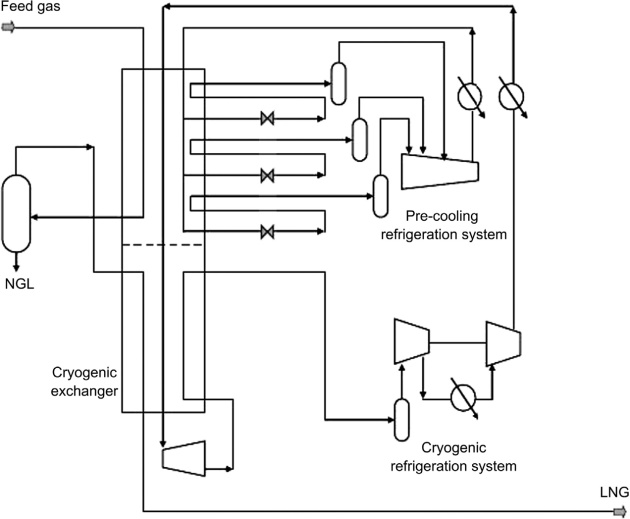
Shell has developed a dual mixed refrigerant (DMR) process for natural gas liquefaction, as shown in Figure 8, with two separate mixed refrigerant cooling cycles, one for precooling of the gas to approximately -50 °C and one for final cooling and liquefaction of the gas. This concept allows the designer to choose the load on each cycle. The technology was deployed for the first time at base load scale at the Sakhalin Liquefaction plant in eastern Russia (i.e., two 4.8 MTPA trains using SWHEs and air cooling enhanced by the cold climate), which was commissioned in early 2009.
DMR process configuration is similar to the propane precooled mixed refrigerant (C3-MR) process, but with the precooling conducted by a mixed refrigerant (made up mainly of ethane and propane) rather than pure propane. The DMR process can be highly efficient in cold climates since the precooling mixed refrigerant can be formulated to avoid temperature and handling limitations associated with propane. Another main difference is that the precooling is carried out in SWHEs rather than core-in-kettle or plate-fin heat exchangers. The cooling duty for liquefaction of the natural gas is provided by a second mixed refrigerant cycle. The refrigerant of this cycle consists of a mixture of nitrogen, methane, ethane, and propane. Mixed refrigerant vapor leaving the main cryogenic heat exchanger is compressed in an axial compressor followed by a two-stage centrifugal compressor. Intercooling and initial desuperheating is achieved by air cooling. Further desuperheating and partial condensation is achieved by the precooling mixed refrigerant cycle. The mixed refrigerant vapor and liquid are separated and further cooled in the main cryogenic heat exchanger, except for a small slipstream of vapor mixed refrigerant, which is routed to the end flash exchanger.
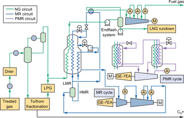
A further development of the DMR process is the electrically driven Parallel Mixed Refrigerant PMR design using a parallel line-up of electrically driven refrigerant compressors around a common set of cryogenic spool wound exchangers. Electric motors of 65 MW have already been constructed for LNG service. Motors up to 80 MW are considered feasible. The current electrically driven DMR design is particularly attractive in the 5 to 10 MTPA capacity range. Electrically driven LNG trains can compete with mechanically driven trains because the increase in availability compensates for the increase in cost. Other benefits of the electric option are the variable size and speed of the driver, the higher vendor base, and the potential to make a step change reduction in overall plant carbon dioxide (CO2) emissions by using the highly efficient combined cycle electric power generation plants.
Suggested reading: Safety Precautions and Measures on Gas tankers
Shell has also developed technology to further push the capacity of the propane cycle by employing double-casing instead of single-casing equipment. This is a reliable method to bring the propane-MR process closer to a capacity of 5 MTPA. With a single precooling cycle and two parallel mixed refrigerant cycles, the capacity can also be boosted up to 8 MMTPA with three General Electric frame seven (GE-F7) compressors in a tropical climate. The process can use either C3 or an MR in precooling. Proven refrigerant cycles can be used and the design can currently be applied without step changes in technology. The capacity can be increased further with different (larger) drivers. Another possibility for the propane-MR process is to transfer power from the propane cycle to the mixed refrigerant cycle, a concept developed by APCI. The closer coupling between the two cycles by mechanical interlinking of compressors is an operational challenge.
Process selection
A qualitative comparison of the different liquefaction cycle is summarized in Table 2. In general, expander plants are favored on the small peak-shave facilities, and the mixed refrigerant cycle (MRC) plants are more attractive for mid-scale LNG plants. For base load LNG plants, propane precooled MRC, cascade, or dual cycle is favored due to their higher efficiency.
It should be noted that liquefaction process selection is critical to the LNG economics, so it is a key activity that starts at an early stage of an LNG project and should be addressed at the feasibility study and pre-FEED stages. Sufficient process and utility details must be developed to define the capital and operating costs for each licensor. Quotations from the various licensors and main equipment vendors must be obtained for the different processes.
In selecting the most appropriate technology, both technical and economic considerations must be addressed. Technical considerations include licensor experience, plant reliability and availability, energy efficiency, and environmental impacts. Economic evaluation must address the life cycle costs, including units upstream and downstream of the LNG plant; and utility and offsite cost. In most cases, process licensors have to adjust and optimize their designs to meet the owners’ preferences, economic criteria, site conditions, and product specifications. Most often, several sets of feed gas compositions must be considered to make sure that the selected process would meet any future requirements.
Thermal efficiency
Thermal efficiency, or train efficiency, is expressed as the ratio of the total higher heating value (HHV) of the liquefied product to the total higher heating value of the feed gas. When evaluating thermal efficiency of a particular Liquefied Natural Gas Projects, calculation of the cost of gas production
LNG liquefaction technology, all the energy being consumed in the process must be considered. Thermal efficiency is a common benchmark used to compare competing processes for new projects. The value of thermal efficiency can have more weighting when the feed gas to the LNG plant is relatively expensive or supply is limited.
Thermal efficiency depends on numerous factors, such as gas composition, inlet gas pressure and temperature, site temperature and pressure, and the other more obscure factors such as location of the loading area relative to the liquefaction process. Thermal efficiency calculated for the LNG loaded to the ship will be less than the thermal efficiency calculated based on the LNG run down from the liquefaction train, as the former will include boil-off losses in LNG storage and energy consumed in loading the LNG to the ship.
Thermal efficiency is a trade-off between capital and life cycle costs. The gas turbine driver selection, waste heat recovery, boil-off gas recovery, end-flash design, utility, and offsite system must be included in calculating the liquefaction thermal efficiency.
Equipment selection
The economics of the liquefaction processes, more than any other units in the LNG supply chain, are dependent on the equipment selection. The efficiencies and costs of the major equipment are some of the important parameters in the selection process. The other more important factors are proven equipment with successful track records, and the confidence of the plant owners in the technology. Equipment must be supplied by reliable suppliers with good financial backgrounds.
Despite the emphasize on proven equipment, the LNG would accept step changes on equipment improvement, such as size increase and efficiency improvement, as long as they are based on familiar technology and equipment.
The advancement in technology is discussed in Chapter 10. This section provides general back-ground information on equipment that is commonly used in the liquefaction processes.
Compressors. The rotating equipment selection is affected by the characteristics of the process, such as gas composition, molecular weight, pressure and temperature, compression ratio, and flow rate of the refrigerant. Typically, the economical choice of a refrigeration compressor in base load plants is the centrifugal compressor because it can be designed with high volumetric flow. Axial compressors are more suited to higher flow rates but at lower pressure ratios than that required by the MR compressors. However, if the refrigeration process is configured to take advantage of the high efficiency of the axial compressor, it can be used as the first stage of compression, but the design has to be optimized together with the rest of the compression train. As for the small to mid-range LNG plants, a wide range of compressors can be considered.
Drivers. Many earlier base load liquefaction plants used steam turbine drivers since they were a proven technology at the time. But as gas turbine size increased and efficiency improved, gas turbines have replaced the steam turbine driver. Operation of a gas turbine is much simpler than a steam power plant. Operating a steam boiler plant is significantly more complex, which is not suitable in remote locations with limited technical supports or in desert locations where water supply is scarce. For these reasons, gas turbines are the dominating drivers for today’s liquefaction plant design.
Gas turbines are more compact than steam systems. The gas turbine delivery schedule and installation time are also shorter than for a steam turbine system. The gas turbine types can be broadly categorized as heavy-duty industrial types (Frame turbines) and industrial aero-derivatives, characterized by their light weight and higher efficiency. The per-formance and design of some of the common gas turbines for LNG plants are shown in Table 3.
Up to now, almost all the refrigerant compressors in liquefaction plants are driven by frame-type gas turbines. The industrial type turbines are heavier in weight but more robust and able to operate under harsh conditions. These turbines have been workhorses for the gas processing industries. The GE Frame 5 turbine has established itself as the prime driver for most compression units and is well accepted by the industry. The Frame 5 output has been slowly increased throughout the years. As shown in Table 3, the power output of Frame 5D can reach 32.6 MW. The bigger frames are now available with Frame 9E reaching 123 MW power. With the larger frame turbine, the cost of power ($/kW) is reduced. To take advantage of the lower cost, the refrigeration cycles must be reconfigured to utilize the larger turbine power. The objective is to design the liquefaction process to utilize the maximum power output from these large drivers.
For the small frame turbines, the power output can also be increased with the use of electric helper motors. This is necessary during summer operation at high ambient temperatures, when the turbine power output will drop and Fundamentals of Liquefied Natural Gas
LNG production will suffer. This deficiency can be compensated by inlet air chilling or with the use of a helper motor.
Aero-derivative gas turbines. Driver selection criteriaAs shown in Table 3, aero-derivative gas turbines can achieve about 25 % higher thermal efficiencies than industrial gas turbines. Aero-derivative turbines operate with a higher compression ratio and a combustion higher inlet temperature. However, the maintenance costs are typically higher than frame turbines. The turbine availability is also lower due to the less robust design compared to the frame type turbines. However, the change-out of the turbine part is easier because of the compact and lightweight design.
Aero-derivative gas turbines were successfully installed and operated in the optimized cascade liquefaction trains of the Darwin LNG facility. The positive feedback from plant operation was the ability to swap out a gas turbine generation set in less than three days. This compares to the typical 14-plus days turnaround for a major overhaul on an industrial gas turbine. The short turnaround time has improved the overall plant availability of an aeroderivative turbine, despite the more frequent outages.
Note that the original designs using the Phillips Optimized Cascade Liquefaction Process (POCLP) were based on the Frame 5 series gas turbines. The LNG output capacities using the Frame 5 turbines ranges from 3.3 to 3.7 MTPA (e.g., Atlantic LNG facility, Trinidad Trains 1 to 3; Idku LNG Egypt; Darwin LNG Australia and Bioko LNG, Equatorial Guinea).
Large gas turbine drivers. To take advantage of the larger gas turbine drivers, the liquefaction train design is configured to match the available driver capacity, and the lower cost of power $/kW (see Table 3).
For larger LNG trains, Frame 6, 7EA or Frame 9E industrial gas turbines are a better fit (Avidan et al., 2003).
The Soyo LNG Plant in Angola (5.2 MTPA single train design, onstream 2012) utilizes a combination of Frame 6 and Frame 7 compressor drivers in a two-train-in-one configuration.
A Frame 9 gas turbine with 130 MW ISO rating provides 50 % more power than a Frame 7. The six large (7.8 MTPA single train capacities) trains in Qatar (2007 to 2011) use three Frame 9 gas turbines for each train. Operating at slower speeds (3 000 rpm versus 3 600 rpm) further increases the power output from the Frame 9 turbines.
Driver selection criteria. With direct gas turbine drive, the match of the drivers’ design to the refrigeration compressors is crucial in the liquefaction process selection. If the compressor driver train is not limiting, then the other equipment in the liquefaction train needs to be evaluated. Most importantly, the licensor must be confident in the plant performance when extending their technology on building larger heat exchanger equipment; that is, the main cryogenic exchanger.
If the large equipment size is not viable or economical, then parallel trains can be considered. The parallel trains would undoubtedly drive up the capital costs, but the additional equipment may also improve the plant availability and flexibility that may be favorable in some cases.
In most cases, the selection criteria is the match of the gas turbine sizes to the liquefaction designs that would result in higher efficiency and lower capital cost. However, with the availability of large electric motors, the liquefaction process is no longer limited by the mechanical drivers. This would open up more opportunities for innovation and efficiency improvement.
Heat exchangers. The main heat exchangers used in gas liquefaction process trains are: plate-fin heat exchangers (PFHEs) and spiral-wound heat exchangers (SWHEs). These types of exchangers have large internal surface areas consisting of a large number of heat exchanger cores or circuits. These designs can achieve a close temperature approach between the refrigerant and the natural gas in the liquefaction cycle.
However, with today’s technology, there is a limit on the heat exchanger size. A single PFHE can typically be designed to liquefy about 1.5 MTPA of LNG. Higher capacity would require multiple exchanger cores grouped together to provide the heat exchange areas. On the other hand, a single SWHE can typically be designed for 4 MTPA of LNG.
PFHEs, often referred to as brazed aluminum heat exchangers (BAHXs), consist of aluminum fins. PFHEs can be configured with different flow configurations: cross-current, parallel, and multipass directions. This type of heat exchanger is also very common in the NGL recovery unit to achieve high recovery. The PFHEs are manufactured by several heat exchanger manufacturers, and are readily available. The main advantages of the PFHE are their compactness, low equipment weight, small foot-prints, and typically lower capital cost. They can be configured to accommodate different processes with multiple exchangers. Since they are constructed of aluminum, they are also more vulnerable to mechanical damages or damage from thermal shocks. The process must be operated to ensure a temperature difference among the different passes of no more than 50 °F to minimize thermal stress.
SWHEs, or spiral (or coiled) wound heat exchangers, are designed with a greater internal heat transfer area and therefore can operate with a larger temperature gradient. In addition to the larger surface area, the other advantage of the SWHE is its higher proven tolerance to thermal shocks. However, because of the fixed heat exchange configuration, the exchanger design has a limited flexibility to handle different feed gas compositions. Compared to PFHEs, this type of exchanger is higher in capital cost, size, and weight. The spiral wound exchanger suppliers are also limited, making them less cost competitive.
In general, the SWHE are used for large MR liquefaction plants, whereas the PFHEs are used in expander and cascade liquefaction plants. However, there are no strict rules in the selection process. The heat exchange equipment selected should be evaluated on a case by case basis, considering the latest advances in technologies. For example, the Statoil/Linde Mixed Fluid Cascade (MFC) process uses both technologies; a PFHE for the first cascade stage and SWHE for the two latter stages. The propane precooled mixed refrigerant (C3-MR) process also uses a combination of PFHEs for precooling and SWHEs for liquefaction.
Heating and cooling
Heating. The main steam consumers in LNG plants are amine reboilers in the amine unit, dehydration regeneration gas heater, tail gas unit reboiler, and reboilers in NGL fractionation. When processing high content sour feed gases, the heating duties for regenerating the amine can be significant. The heating requirement can be supplied by a heat transfer fluid or steam using waste heat from the gas turbines.
If excessive steam is still available after being supplied to the process users, it can be used to produce power using back pressure turbines or condensing steam turbines. The additional power produced can be used to drive the process compressors or one of the refrigeration compressors.
However, with the use of the more efficient gas turbine drivers, the amount of waste heat is expected to be reduced. Worst still, if a combined cycle is used to produce power using gas turbine exhaust heat, the amount of heat available for process heating will be further curtailed. Process heating will then be supplied by steam boiler or by duct firing in the gas turbine exhaust. In this case, the gain in power generation efficiency will be offset by the fuel required for process heating.
To arrive at an optimum process configuration, the plant steam balance and the power block steam and power configuration must be evaluated together with the refrigeration cycles and the plant steam consumption.
Cooling. The main coolant consumers are compressor interstage and discharge coolers in refrigeration units. Process units also require cooling, such as the lean amine cooler, the molecular sieve regeneration gas cooler, sulfur plant product cooler, reflux condensers in the stabilization unit, and the NGL fractionation unit.
There are basically two types of cooling medium: air and water. Therefore, selection of the type of cooling medium is site dependent.
In desert areas where water supply is not available, air cooling is the only solution. Since most of the base load LNG plants are located in desert areas, air cooling is the primary choice. Because of the hot desert ambient, the process may require further cooling below the ambient temperature using refrigeration provided by a chilled water system. For example, General information and Rules for Ships carrying LNG and LPGgas precooling before the molecular sieve unit, which is necessary to reduce the water content before the molecular sieve bed, would significantly reduce the size of the molecular sieve beds. Another example is gas turbine inlet air chilling using refrigeration or evaporative cooling to maximize gas turbine power output.
For plant sites located close to the ocean, seawater can be considered. Seawater supply temperature is typically lower than air temperature, which can potentially reduce the refrigeration compressor horsepower and increase the liquefaction efficiency. However, the higher efficiency must be evaluated against the higher seawater system costs, such as water inlet and outfall structure and piping, seawater pumps, seawater treatment requirement, and seawater environmental impact.
Comparison of power consumption for different technologies
Along the entire LNG supply chain, the liquefaction process plants represent the largest capital expenditure component. For this reason, technology providers and operating companies strive to improve the liquefaction technologies that would result in cost savings in production through economy of scale and process innovations. Besides the liquefaction process, improvements in other processing units that would increase the plant operability and reliability are just as important.
ExxonMobil is in the process of developing a dual mixed refrigerant (DMR) process, utilizing BAHX exchangers and large gas-turbine-driven centrifugal compressors. The objective is to improve scalability and expandability for large-scale gas liquefaction project developments using more generic equipment, while promoting competition among different suppliers, keeping production cost down. The main aim is reducing the specific power requirement and lowering capital cost over traditional technologies.
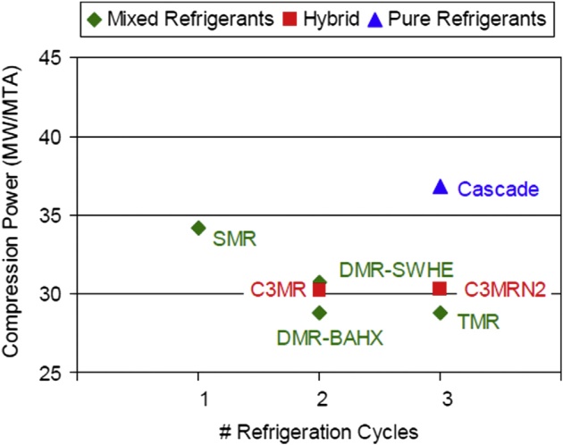
The specific power requirement and the unit cost for some of the latest technologies including the ExxonMobil DMR-BAHX design can be compared in Figures 9 and 10. In these figures, SMR stands for Single Mixed Refrigerant; C3MR stands for Propane Precooled Mixed Refrigerant; C3MRN2 stands for Propane Precooled Mixed Refrigerant plus Nitrogen expander cycle; Cascade uses pure components, such as methane, ethylene and propane; DMR–SWHE stands for Dual Mixed Refrigerant with single pressure levels using SWHEs; DMR–BAHX stands for Dual Mixed Refrigerant with multiple pressure levels using BAHXs; and TMR stands for Triple Mixed Refrigerant.

Liquefaction in cold climates
Exploiting natural gas using gas liquefaction in high latitudes is proven to be commercially viable at some locations (e.g., Alaska, Snohvit, and Sakhalin). The process design of the liquefaction plants in arctic climates presents some unique challenges.
Cold ambient temperature increases the operating efficiencies and reduces the energy consumption in the cryogenic facilities, independent of the liquefaction technology. When compared to hot climate areas, cold climate or arctic areas refrigeration requirements are lower, mainly due to the reduction in refrigeration in the precooling section. The temperature fluctuation affects the precooling section the most since this is where most of the heat is rejected to ambient air.
It is interesting: Environmental Control on Liquefied Gas Carriers
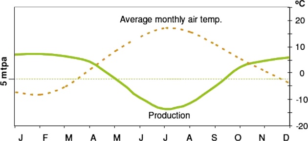
Arctic locations have a wide seasonal variation in ambient temperature, resulting in significant seasonal variations in output (Figure 11), which would require process adjustments throughout the year to maximize the plant throughput. The cold ambient also increases the power output from the gas turbines as the air gets denser, increasing the mass flow to the turbines. This presents a challenge to the owner on whether to invest additional process equipment to take advantage of the higher horsepower output in the winter, while the equipment is underutilized in the summer.
For the extreme weather conditions in the Sakhalin liquefaction plant, ambient temperature can vary from 26° C in the summer to -18 °C in the winter. By adopting the dual mixed refrigerant process and using mixed refrigerants (propane and ethane) for precooling, the ratio of these components can be adjusted to match the seasonal changes in ambient temperature, to minimize energy consumption. Waste heat must be recovered from the gas turbine exhaust to provide heating for heat tracing on equipment to avoid water from freezing in the gas processing units. Operating a steam plant in cold climate areas requires more operator attention.
If liquefaction plants are to be operated at varying throughput based on ambient temperatures, LNG shipping logistics must also be evaluated to cope with such variations. However, this may not always be possible. For instance, colder weather conditions may sometimes lead to shipping delays at a time when the unit is capable of maximum output. For this reason, liquefaction plants are usually not designed to utilize the full capacity of the drivers during winter; the plant capacity must be optimized by simulation model based on logistics and climatic factors, which set a limit or “cap” on peak production.
Cooling medium selection
Cooling medium selection (direct air versus direct seawater) has significant cost and design impacts on LNG plants. Air temperatures vary more widely than seawater temperatures. The colder air in winter has two impacts on refrigeration system performance. Cold inlet air to gas turbines increases gas turbine power output. Colder air also lowers compressor interstage and discharge temperature, resulting in a lower compression requirement. In particular, in the precooling section, process cooling can be partially achieved by air, which significantly reduces the refrigeration requirement. Conversely, during summer, power output from a gas turbine would be reduced and compression cooling is less effective, leading to reduction in production. Unfortunately, the loss in production also coincides with typical plant turnaround in the summer, which further worsens the plant output. Production may be somewhat compensated by the increase in production in winter.
Seawater temperature generally stays fairly constant throughout the year, and the average seawater temperature in high latitudes is typically about 2 to 3 °C higher than the air temperature. While operating in winter, the colder seawater may increase the production somewhat, but the increase is limited by the freezing seawater. In most cases, the capital costs for a seawater cooling system cannot justify the marginal increase in production in winter months. Because of this, coupled with the environmental sensitivity on warm seawater discharge, air cooling is generally the likely choice in arctic locations, except where space is severely limited.
Liquefaction process selection in cold climate
The most widely suitable liquefaction processes are divided between those that are precooled with propane and those with a mixed refrigerant. Because the heat sink in arctic LNG plants is available at such a low temperature, reducing the precooling temperature will allow for a better power balance and better machinery selection between precooling and liquefaction duty. This can be accomplished by replacing the propane refrigerant with a lower boiling point gas (e.g., ethane or ethylene) or a multicomponent mixed refrigerant. Although the mixed-refrigerant system is more complex than a single-component refrigerant system, it provides additional flexibility since the composition of both mixed refrigerants can now be adjusted within certain limits to match the wide seasonal variation of heat-sink temperatures. Thus in winter the lower ambient air can be used to condense a lighter refrigerant at a lower temperature. As the refrigerant is condensing at lower temperature, this can be performed at a lower pressure, so that the compressor can move out along its curve and process a greater refrigerant flow at lower compression ratio, all within a given shaft power. Therefore, overall refrigeration duty can be increased to take advantage of the winter conditions.
Cold climate design issues
As a further challenge to the LNG plant designers and project managers, freezing temperatures, snowfall, and high winds reduce on-site productivity, complicate the transport of personnel and equipment, and extend the construction schedule. Snow and ice loadings have a significant impact on building and structure design.
If installed outdoors, winterization of the gas liquefaction plants is necessary to prevent fluid freezing, liquid drop-out, and wax and hydrate formation. Rotating equipment such as pumps, power generators, and refrigerant gas turbine and compressor units must be housed in heated and ventilated modular buildings.
The construction of the equipment modules is typically completed in modular yards. The completed modules can be shipped to the site for installation. There are special design considerations on modular design, particularly on the piping and electrical layout and configuration, which must be designed to permit easy installation and adequate egress and maintenance.
Offshore natural gas liquefaction
There are many smaller gas fields in remote offshore locations that can benefit from the floating liquefaction (FLNG) technologies. Ship-to-ship LNG transfer and marine vessel LNG storage tank technologies have now evolved to the stage where offshore liquefaction plants with capacities in excess of 4 MTPA are economically viable.
Despite the high cost of the marine vessel, bringing gas to an onshore LNG liquefaction facility can be just as costly. Onshore installation requires extensive infrastructure, including subsea pipeline, gas separation equipment, storage tanks, dredging for jetties, and other port facility. Construction of such facilities will require extensive time. In some instances, FLNG solution offers the only viable solution that allows completion of the project in a short schedule. Quality of the FLNG design can also be better managed and controlled.
LNG floating production, storage, and offloading (LNG FPSO) has been the focus of research and development since the 1980s, but in 2008 it took a step toward deployment with the commitment by FLEX LNG Ltd to contract Samsung to construct vessels for service offshore with provisional locations in Papua New Guinea. In 2011, FLNG took another big step forward when Shell announced its decision to build a large FLNG vessel to develop the Prelude gas field offshore Northwest Shelf (NWS) Australia for deployment in 2016/2017.
Assessment of liquefaction technology to offshore FLNG is no different than onshore installation, and the life cycle cost analysis must be evaluated with the same process as a land-based plant, with safety being of paramount importance. However, for offshore floating liquefaction, the criteria for technology selection differ substantially from onshore facilities. While thermodynamic efficiency and train capacity are important criteria for landbased plants, the cost of an offshore facility relies on small footprint, low equipment count and weight, and compact modules. While cost is an important criterion, the offshore design must provide easy access to maintenance, must be easy to start up and shut down, and must be reliable. Being an under-ocean environment, the motion of the vessel must be considered in equipment design, such as in fractionator design where motion can impact flow distribution on trays that can lower fractionation efficiency. The following section reviews the different liquefaction cycles in respect to the offshore criteria.
Refrigeration cycles
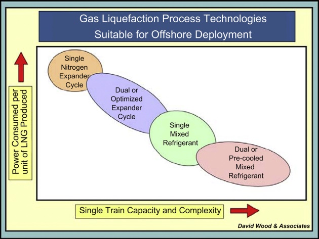
A key decision in the development of FLNG projects is the selection of the liquefaction process cycle that best meets the project objectives. Three generic types of refrigeration cycle have been considered for offshore natural gas liquefaction: cascade, mixed refrigerant, and expander. Previous sections have discussed the performance and requirements of these technologies in land-based environments. The following section reviews the characteristics of each process with respect to offshore functionality and explains why the cascade technologies have been largely discounted for FLNG deployment. Figure 12 highlights the trade-off between process efficiency and plant complexity for expander and mixed refrigerant technologies. The selection process is more difficult, may not be cost dependent, and may depend on the availability of technical staff to operate a complex facility.
Cascade and optimized cascade
The cascade cycle specific power is low but the process is relatively complex and involves a large number of equipment items. Each of the three refrigerants requires its own storage. The refrigerants would need to be fractionated from the feed gas, and the purity must be monitored and controlled.
For offshore installation, the cascade cycle has the disadvantage despite its high efficiency. It has three refrigeration circuits driven by individual compressors, and each refrigerant has its own liquid storage. The large number of equipment counts and the large plot requirement increase the cost of the FLNG where space is a premium.
Propane precooled mixed refrigerant
Compared to the cascade processes, the propane precooled mixed refrigerant (C3-MR) process by APCI has less equipment counts but is still quite complex to operate in an offshore environment. The use of propane refrigerant in the precooling loop requires propane storage, which is a safety hazard in the close environment of an offshore facility. The liquid inventory in kettle-type heat exchangers is a potential hazard. The heat exchange equipment can be impacted by the vessel motion and the sloshing of liquid. A different type of heat exchanger may need to be used that are more resistant to motion to ensure good distribution and effective heat transfer.
Mixed refrigerant
Mixed refrigerant technology has been assessed for offshore liquefaction based on both single mixed refrigerant (SMR) and dual mixed refrigerant (DMR) cycles.
For smaller-scale facilities, the simplicity of the SMR technology has some attractions for offshore deployment. However, the SMR process requires a single large liquefaction coil-wound heat exchanger (CWHE) as opposed to the DMR cycle because it must handle all the liquefaction duty including precooling in one exchange. This exchanger is more difficult to install in FLNG for structural and process reasons. At capacities greater than 2 MTPA, two CWHEs would likely be required. A basic SMR process has a lower efficiency than a C3MR or DMR cycle. The process can be somewhat improved with an additional compression and heat exchanger, but at the expense of equipment count and complexity.
The DMR cycle is more efficient, but more complex. It has less hydrocarbon inventory compared to the SMR cycle and the C3MR cycle. The relief rates are lower than other processes in the event of compressor trip and overpressure. However, all mixed refrigerant cycles require storage of hydrocarbons and fractionation facilities for refrigerant makeup. The safety concerns of hydrocarbon liquid storage are the major hurdles for acceptance of mixed refrigerant technology offshore. Operating an offshore facility is more complex than an onshore facility because it is exposed to extreme weather conditions and other hazards. Thermal efficiency is less important, and operators will be less likely to have the time to monitor and adjust the refrigerant mix for efficiency gain .
Expander
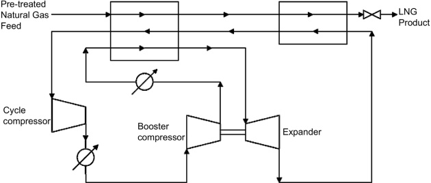
Turbo-expander refrigeration cycles work by compressing and work-expanding a suitable fluid, typically nitrogen or methane, to generate refrigeration (Figure 13). The expander cycle is simple and has fewer equipment counts than other refrigeration cycles. This equipment can be modularized, requiring smaller plot space, resulting in lower plant cost. Heat exchangers use conventional brazed aluminum exchangers and can be arranged in various configurations. Note that although the refrigerant circulation rate and main heat exchanger duty are significantly lower in expander cycles, the required heat transfer surface area could be higher because the heat transfer coefficient of nitrogen is much lower than hydrocarbons.
Expander technology is being promoted for FLNG on the basis that it demonstrates:
- Inherent safety with nitrogen as the refrigerant, and there are no liquid hydrocarbon refrigerants and no potential fire hazards;
- Insensitivity to vessel motion as the refrigerant is in gas phase, and there is no concern on refrigerant distribution in heat exchangers;
- Flexibility to changes in feed gas conditions and ease of operation;
- Rapid startup and shutdown;
- Less equipment counts, smaller plant footprint, and relatively low topside weight.
The trade-off is its lower thermal efficiency compared to other technologies. The expansion cycle can be operated with a closed loop nitrogen cycle or open loop feed gas cycle.
N2 expansion cycles are proven at small LNG plants, in peak-shaving plants, and in reliquefaction of boil-off gas in recent LNG carriers. The main advantage of nitrogen as the cycle fluid is that it is inherently safe. Other more efficient cycles require hydrocarbon liquid storage, which is potentially a fire hazard. In addition, the nitrogen cycle system is compact as it does not require any refrigerant storage and makeup. System turndown changes can be accommodated with a nitrogen gas surge drum. There is no mal-distribution in the heat exchangers because itis in gas phase. Exchanger and column performance where distribution is critical is not affected by motion in the offshore vessel.
The nitrogen expander design is flexible to changes in feed gas composition and feed gas conditions. There is a side benefit of the less efficient cycle. The temperature approaches on heat exchangers are significantly larger than the mixed refrigeration cycles, and hence adjusting the process parameters to accommodate any feed gas composition changes is simple. With this flexibility, the FLNG can be used to process other gas fields when the gas resource is depleted, extending the usable life of the liquefaction plant.
Compared to the mixed refrigerant cycle, there is no composition adjustment required in handling different gases, because it is a pure component system. Startup and shutdown is quick. Venting in an emergency situation is not a safety concern. No flaring is necessary. However, the refrigerant flow is significantly higher than the mixed refrigeration cycle, since it depends on sensible heat of the gas phase for cooling, and single train capacity is typically limited to 1 to 2 MTPA.
There are several configurations that strive to improve the efficiency of the basic expander tech-nology. The expander cycle efficiency can be increased with the use of a propane precooled cycle. Propane is a more efficient cycle as it can better match the higher end of the LNG cooling curve than the nitrogen cycle. However, the use of propane for refrigerant defeats the advantage of the safety claims of the nitrogen cycle, and is not favored in an offshore environment. Alternatively, a second colder turbo-expander (Figure 14) can be used to close up the temperature difference in the cold end of the nitrogen/LNG heat curve. However, this configuration would require more heat exchanger surfaces and the capital cost is higher.

The dual turbo-expander process has been proposed for several projects. In the late 1980s, Costain advocated a dual turbo-expander flowsheet based on nitrogen refrigerant for the Pandora field, offshore Papua New Guinea, in conjunction with Three Quays Marine Services Ltd. BHP Ltd and Linde AG also proposed the use of a dual nitrogen expander cycle to develop the Bayu-Undan field in the Timor Sea. The use of dual turbo-expander cycle is commonly accepted for offshore deployment.
Some expander cycles also use feed gas as the refrigerant; for example, Mustang Engineering’s OCX-2® process and Kryopak’s EXP® cycle. The gas expansion cycle uses the feed gas as the refrigerant and can be operated in an open cycle configuration, eliminating the need for refrigerant supply, further simplifying the expander process. The feed gas expander cycle has the same attributes as the nitrogen cycle with the exception that special attention is required for operating the expander compressor as any relief must be vented to a safe location to avoid fire hazard.
Process selection
To select the most appropriate offshore natural gas liquefaction cycle, we must compare the options with the major criteria that influence commercial acceptance of floating LNG production. Table 4 summarizes the evaluation of liquefaction cycles for offshore use. Although the dual nitrogen expander cycle requires more power than the more complex and thermodynamically efficient cycles Dual nitrogen expander processes for gas liquefaction are expected to achieve unit power requirements of between about 15 and 20 kW*day/ton. Propane precooled dual expander processes may approach the efficiencies (about 13.5 kW*day/ton) of state-of-the-art C3MR cycles.x, the simplicity of the process and the other critical factors listed make it a strong candidate for many floating liquefaction projects.
In addition to the various items outlined earlier, there are a number of factors such as machinery configuration and types of drivers, heat exchanger type and area, and utility and offsite systems that also must be addressed to determine the optimal FLNG process technology.
Choice of compressor driver
Onshore liquefaction plants typically use refrigerant compressors driven by industrial heavy-duty gas turbines, but these are difficult to deploy on a FLNG vessel. Aero-derivative gas turbines are likely to be used in FLNG vessels because of their:
- High power-to-weight ratio resulting in smaller footprints and about half the weight of a standard industrial compressor of comparable power output;
- Proven availability and reliability;
- Modular engine sections that are easy to service and maintain;
- High thermal efficiency (i.e., greater than 40 %) compared to industrial units that results in lower fuel consumption and less carbon emissions.
The LNG industry has been using the industrial gas turbines for refrigeration compressor drivers for the past decades. The adoption of the aero gas turbine for the gas processing industry has been slow. However, with the many advantages of the aero turbines and the potential capital cost and energy savings, the use of the aero gas turbines is being accepted for process drivers, particularly in smaller LNG plants and in offshore applications. For example, the Darwin LNG plant (Australia) uses GE LM 2 500 + aero-derivative gas turbines as the refrigerant compressor drivers and has been in successful operation since 2006.
Liquefaction heat exchangers
Aluminum plate-fin heat exchangers, which are lightweight and compact, are ideal for floating lique-faction plants. The plate-fin heat exchanger consists of several heat exchanger blocks or cores that are installed inside an insulated cold box. While the exchangers are designed for close temperature approaches, excursion to high temperature differential must be avoided as it would impose excessive thermal stress, which may occur during startup or off-design conditions. There are no special me-chanical design or exchanger support issues as long as the design temperature not exceeding 150 °F. The challenge is the piping integrity in the transition from stainless steel piping to aluminum flanges of the exchangers which can now be resolved with cryogenic aluminum to stainless steel transitional joints. The system must also be designed considering the stress imposed by the vessel movement.
Utility systems
Process cooling systems in FLNG typically use seawater, because air coolers would take up extensive deck space. Seawater cooling can be in either an open or closed loop. In an open loop system, seawater is drawn in, filtered, treated to avoid fouling, pumped through the heat exchangers in the refrigeration systems, and then discharged back to the sea. The heat exchangers are shell and tube exchangers with the exchanger tubes constructed of seawater corrosion-resistant material such as titanium. In the closed loop system, inhibited water is pumped to the heat exchangers and heat is rejected to seawater using a plate and frame exchanger. The closed loop system can be constructed of the less expensive carbon steel material. The indirect heat exchange system in the closed loop circuit increases the coolant supply temperature, which may have a minor impact on the thermal efficiency of the refrigeration cycle.
Waste heat from gas turbine exhaust is recovered to provide process heating in the gas condition units.
For operation simplicity, heat transfer fluid such as Dowtherm or Therminol is preferred to steam, as it avoids the operation complexity and the weight of a steam generation plant. For higher efficiency, the steam generation can produce high pressure steam to drive one of the refrigeration compressors. However, in cold climate operation, a steam plant is difficult to operate and is generally avoided.
Small to mid-scale liquefaction processes
The cost index of LNG liquefaction plants was decreasing because of economy of scale up until 2005, but since then, the cost index has been increasing significantly, especially the Australian plants due to high labor cost and escalation of materials. This trend increases the risks on the return on capital, dampening the venture capital’s appetite on commitment to large-scale projects. However, a number of medium and smaller sized gas reservoirs, especially less than 5 TCF, are undeveloped. The number of these reserves is over 1,000. These reservoirs are held not only by major oil companies but also by small oil companies or national oil companies. If a good solution for monetizing these reservoirs, such as stranded-gas or associated-gas, is found, projects will be active for such medium-sized gas development.
There are many applications for the small-scale LNG plants: peaking shaving plants, satellite LNG plants for gas transport where pipeline is nonexistent, on-board ship liquefaction, coal bed methane recovery, and bio-gas, landfill gas and today’s shale gas liquefaction. For example in Queensland Australia, four mid-scale LNG projects are being developed to liquefy CBM gas on a base load scale project targeted for the Asian markets.
Small to mid-scale liquefaction plants, typically up to 1 MTPA capacity, generally focus upon standardizing compact, preassembled modular designs that can be deployed quickly minimizing design and construction costs. These plants typically are designed with the following objectives:
- Process simplicity;
- Safety;
- Easy operation;
- Low Cost;
- Plant reliability.
There are several small and medium-scale gas liquefaction plants in operation around the world. Plants of this scale are typically sized to process between about 2.5 MMscfd and 100 MMscfd, which is about 10 % of the capacity of a base load liquefaction plant. Existing LNG production plants in the small-scale area employ a variety of liquefaction technologies. In general, the small to mid-scale liquefaction plant use one of two processes; that is, single mixed refrigerant or gas expansion-based technologies. The characteristics of the representative processes are discussed next.
PRICO process
The PRICO (Poly Refrigerated Integrated Cycle Operation) process, as discussed in Section 3.2.3.3, uses a Black & Veatch patented, single-mixed refrigerant loop for natural gas liquefaction. This process has made Black & Veatch an industry leader for both onshore and offshore small to mid-scale liquefied natural gas applications. As a reference, 25 % of the peak-shaving US plants use this process, and, as already mentioned, several liquefaction plants using this technology have been built in China in recent years.
APCI single mixed refrigerant process
JGC (Japan) have worked with APCI for possible Asian deployments for a liquefaction plant with 0.5 to 1.0 MTPA capacity. The generic compact design offered by JGC/APCI involves feed gas inflow at 60-bar pressure and 30 °C temperature and includes a plant configuration with the following process components:
- Gas receiving and acid gas removal unit ( up to 6 % CO2);
- Dehydration unit;
- Liquefaction units (scrubber and liquefaction; each unit of 0.5 MTPA capacity);
- Fractionation unit (for refrigerant make-up);
- Fuel/hot oil unit;
- Centrifugal refrigerant compressor;
- Gas turbine Frame 5D compressor driver;
- Air cooling;
- Hot oil process heating;
- No end-flash or expander units involved.
The specific power requirements for this design was quoted as between 385 kWh/ton of LNG (holding mode) and 398 kWh/ton of LNG (loading mode) and claimed to be lower than alternative processes for comparable plant capacities. The plant as described fit into an area of 218 m x 136 m. Preliminary cost estimates for installation of process units only quoted by Matsui and Yatsuhashi (2010) varied from $400/tpa (Indonesia location) to $600/tpa (East Coast of Australia location).
Linde multistage mixed refrigerant process
The Linde Multistage Mixed Refrigerant (LiMuM®) process consists of a Spiral Wound Heat Exchanger (SWHE) and one three-stage single mixed refrigerant loop for the precooling, liquefaction, and subcooling of the natural gas. This process can also be scaled up if required (e.g., up to 2.5 MTPA) by adopting a two-in-one configuration for the refrigerant compressors (barrel type). An operating plant using this process is the Shan Shan LNG plant (China), with a capacity of 0.43 MTPA.
Kryopak precooled mixed refrigerant process
The Precooled Mixed Refrigerant (PCMR®) is a process offered by Kryopak, which consists of a precooling stage (ammonia or propane cycle) followed by a single mixed refrigerant cycle, where the mixed refrigerant is a mixture of nitrogen, methane, ethane, propane, and butanes. The heat exchangers are of the BAHX type. This process is used in some small-scale liquefaction plants with a capacity less than 0.1 MTPA. For example the Karratha LNG project in Western Australia produces some 200 tons of LNG/day (i.e., approximately 0.07 MTPA). The LNG produced at the Karratha plant is then delivered via “road-train” (i.e., very large road vehicles) to small communities in Northwestern Australia up to distances of 2 000 km from the liquefaction plant.
Optimized single mixed refrigerant process
The Optimized Single Mixed Refrigerant (OSMR™) process, offered by LNG Limited, is a single mixed refrigerant process complemented with a standard package ammonia absorption process.
Within the SMR cycle, the main compressor comprises a single stage unit and the cold box optimizes the passes of the streams (3 main streams plus 2 minor streams). The utilization of an ammonia process allows an improvement of the efficiency of the process and an increase of the LNG output compared to traditional SMR processes. It also allows a reduction in the cold box size. Plans to utilize this technology on larger-scale coal bed methane to LNG are being advanced by LNG Limited for the Gladstone LNG ProjectdFisherman’s Landing, in Australia. The first phase of that project as planned involves a plant capacity of 1.5 MTPA with a possible scale-up to 3 MTPA in a second phase. Several features of the OSMR® LNG process, including the use of a combined heat and power plant recovering waste heat from the gas turbines, allows the Fisherman’s Landing LNG project as designed to offer reduced CO2 emissions (i.e., with a confirmed design rate of 0.21 tCO2e/tLNG) relative to the other CBM to LNG projects under construction at Gladstone.
Hamworthy closed nitrogen expansion cycle
This system is designed and deployed mainly on LNG ships to reliquefy boil-off gas during their voyages. It is used on several membrane tankers serving Qatar LNG supply chains. The Moss RS concept is based on a closed nitrogen expansion cycle extracting heat from the boil-off gas. The BOG is cooled and condensed to LNG in a cryogenic heat exchanger (cold box) involving a nitrogencompander with coolers (one expander). Noncondensable items, mainly nitrogen, are removed in a separator vessel. From the separator, the LNG is returned to the ship’s cargo tanks by the differential pressure in the system. Hamworthy’s Mark III design adds a compressor in order to reduce power consumption and increase liquefaction capacity of BOG.
Mustang OCX-2 process
The OCX-2 (Open Cycle Expander Refrigeration, second generation), offered by Mustang, is an expansion-based liquefaction technology that uses the inlet gas as a refrigerant in an open refrigerant cycle with turbo-expanders. OCX-2 is claimed to achieve 89 to 92 % thermal efficiency and is targeted for mid-scale (0.5 to 2 MTPA) applications.
CB&I Lummus Niche LNG process
The CB&I Lummus patented Niche LNG process (targeting small to mid-scale LNG applications up to 2 MTPA) is a dual expansion methane/nitrogen technology in which the methane cycle provides cooling at moderate and warm levels while the nitrogen cycle provides refrigeration at the lowest temperature level. There are no operating references for this process, but it is being actively promoted for FLNG.
Note, for small to medium-size natural gas liquefaction capacities, expander processes have attracted growing interest over the last decade. One of the main reasons for this is the applicability for floating LNG production, because of the simplicity, safety, and the operational advantages of a gaseous refrigerant. However, the selection of the most appropriate small scale liquefaction (SSL) technology is very case-specific. The most relevant parameters to be considered in the selection will depend on the particular conditions of a project (including feed gas composition and feed gas pressure), where every project has its own priorities and the selection criteria may change when the bases of design of the project change. Likewise, the weighting factors assigned to the main parameters in the selection process will vary in each project.
Pressurized LNG concepts
Pressurized LNG (PLNG) containment was described by Fairchild et al. (2005) and patented by ExxonMobil. Such storage conditions allow LNG to be contained at warmer temperatures at a higher pressure than conventional. The higher temperature reduces the refrigeration requirement significantly, leading to possible cost savings. The key component of the ExxonMobil’s technology is the containment system. The PLNG pressure vessels are made of a newly developed high strength, low temperature (HSLT) steel along with a novel welding technique and welding consumable. In order to confirm the design and fabrication methods for these PLNG containers, ExxonMobil fabricated and hydro-tested PLNG prototype container (i.e., 5 m diameter by 18 m tall) using the new HSLT steel and welding method.
The potential savings of PLNG are, however, somewhat offset by the higher cost of the vessels, and the heavier vessels. To commercialize the PLNG technology, the design of the PLNG ship must be fully developed to assess the economic viability of this concept.
More recently Daewoo Shipbuilding & Marine Engineering (DSME) has developed and patented their “Cluster LNG” concep as an integrated liquefaction, transportation, and regasification supply chain of pressurized LNG. LNG is maintained at a temperature of -110 °C and at a pressure of 20 bars along the supply chain. DSME claim substantially reduced energy requirements and lower capital and operating costs for the supply chain as a whole, but note that the costs of the transport and regasification are expected to be higher when compared to conventional systems. This is in part because per unit volume the PLNG at Cluster LNG conditions contains about 20 % less gas than conventional LNG.
DSME also claim that their Cluster LNG design can cope with lower quality gas (i.e., higher CO2, water and sulfur), significantly reducing the requirement for pretreatment of feed gas in many cases. The Cluster LNG system claims that it can accept approximately 1 % of CO2 for the liquefaction plant and related systems.
The PLNG concept has yet to be used as part of a commercial development but is likely to be further developed over the coming years and deployed as part of a small-scale supply chain development (e.g., island-to-island gas movements within Indonesia focused on developing small-scale reserves).