Explore the critical considerations for managing pipelines in marine terminals when handling liquefied gas. This article delves into safety protocols, regulatory compliance, infrastructure requirements, and best practices to ensure efficient and secure operations.
Learn how to mitigate risks and enhance the performance of your marine terminal’s liquefied gas handling processes.
Surge Pressures
In this section the question of ship loading is addressed firstly because these operations are the ones most likely to attract the highest surge pressures. Particular issues relating to cargo discharge are covered later.
Ship Loading
The problems of surge pressure on ESD can be reduced if the terminal and the ship ESD systems are linked (to act in combination) such that:
1 Pumps are stopped;
2 (a) On loading, the terminal ESD valve will shut first, and;
2 (b) On discharging, the ship’s ESD valve will shut first.
Also, it should be noted that ship’s pipelines, in the refrigerated trades, may only be designed for a 10 bar working pressure whereas those on shore will normally be designed for 19 bar. The lower pressure rating on these ships can add an extra risk to the surge problem.
The foregoing points provide the main reason for including this section in the report. Additionally, there are accident reports on record pointing to surge pressure considerations.
At first glance the benefit of Emergency Shut-Down and Emergency ReleaseESD valves seems obvious. However, valve closure against cargo flow can have serious side-effects such as the bursting of pipelines, hoses or hard-arms, therefore the phenomenon of surge pressure has to be taken into account. Accordingly, when establishing the proper operation of ESD valves it is first necessary for terminals to consider how surge pressures may be generated in a pipeline system and then to establish how these effects can be contained or minimised. This is necessary not only for the shore system but also within the ship’s manifold piping. It is only after this has been done that the combination of pumping rates and valve closure times can be optimised.
On this subject it is worthy of note that surge pressures can be more severe when pumping liquefied gas cargoes as compared to other products. This is because gas cargoes are only ever in association with their own gas. Products such as oil cargoes may mix with air or inert gas and, even in very small admixed quantities, this effect can produce significant buffering.
Most of the arguments in this section are solved where a linked ship/shore ESD system is fitted. With this equipment, if loading, the shore valve would always be programmed to shut first. In this way the ship/shore connection is protected. Without such linkage, safe procedures can seldom be guaranteed. Reference to Emergency Shut-Down and Emergency Release“Larger Terminals” shows that the failure of some shipboard equipment will automatically set a ship’s ESD in motion. Where no ship/shore link is fitted, the ship’s ESD valve would shut first and the connection is endangered. There have been a number of accidents of this type (See Analysis of Incidents“Appendix 1: Known Significant Accidents and Near-Miss Data (c. 1982—1994)”).
Surge Pressure – General
In general, cargo loading rates should be set as a function of:
- An hydraulic analysis of the pipeline and transfer system;
- The ESD valve closure time;
- The characteristics of the valve itself;
- The pipeline length and diameter from shore pump to ship, and;
- The availability of surge pressure relieving devices.
Once a pipeline system is in operation, when considering surge pressures, of all the matters mentioned above, a reduction of the cargo loading rate is most likely to yield immediate benefit. Accordingly, cargo pumping flow rates (in association with shore ESD valve closing times) should be set to limit surge pressure generation to below acceptable levels.
Surge pressures result from rapid changes to cargo flow and reverberate, at the speed of sound (fluid dependant) through the pipeline system. They will be more severe on longer systems. In other words, if a ship is loading and only the ship’s ESD valve is closed, a worst case scenario develops. Similarly, if a ship is discharging and a valve is closed deep inside the terminal a similar risk develops (See Analysis of Incidents“Appendix 1: Known Significant Accidents and Near-Miss Data (c. 1982—1994)”). In an emergency, given that the valve most likely to be closed is situated at the manifold area, on ESD it follows that for any particular terminal, surge pressures will be greater during cargo loading in comparison to cargo discharging.
Read also: Comprehensive Overview of LNG and LPG Cargo Hoses in STS Operations
Accordingly, at loading terminals, it is often found that a quick acting bursting disc (or a quick acting pressure relief valve) is fitted in a pipeline-branch with a connection to a surge drum. The bursting disc is designed to relieve short duration surge pressures (of a damaging nature) so allowing the scantlings of terminal pipework to be optimised. To have immediate effect, the bursting disc and surge drum should be fitted close to the shore ESD valve Where fitted, such systems have the benefit of allowing higher loading rates.
Study of a typical (unprotected) ship/shore pipeline system has shown that excessive pipeline pressure surges can be generated if a valve were to fully close in 15 seconds. The study also found that pipeline pressure surges are much reduced if pumps are stopped at least one pipeline-period before the valve commences closure. Pipeline-periods depend mainly on product type and line length, for example a four kilometre pipeline in refrigerated ammonia has four seconds period, but for a similar line in propane at ambient temperature the pipeline period will be about 15 seconds.
Operational Procedures
Shore management should be guided regarding suitable valve closure times by having access to the hydraulic analysis of the cargo piping system. Generally, for any Linked ESD Systems at Both LNG and LPG Terminalsship/terminal cargo system the optimal pumping rates will depend on the results of hydraulic analysis set against the valve closure time and pressure rating for the system. Here it will be found that slow pumping along with short pipelines can tolerate fast valve closure times but on longer lines slower valve closing times are needed. The maximum valve closure time, as allowed for ships in the IGC Code is 30 seconds. On loading it is therefore clear that shore valves must always fully close in less than 30 seconds. Ship and shore ESD valve-closure-times are adjustable to levels below 30 seconds but it should be kept in mind that valve characteristics will mean that for a 30 second total valve closing time the effective valve closing time may be as little as 15 seconds. This depends on valve characteristics.
For loading terminals without detailed background information, and lacking special devices in pipelines to control surges, some rudimentary information is available which can help to determine suitable cargo loading rates. From an operator’s viewpoint this may be vital information in agreeing the terms of the Ship/Shore Safety Check List.
Amongst other questions, the Ship/Shore Safety Check List asks:
- Have maximum working pressures been agreed between ship and shore? – (Q.6);
- Are emergency shut-down systems working properly? – (Q.10);
- Do ship and shore know the rate of each others ESD valves? – (Q.11);
On question 11 (Q.11 above) the guidelines for the Ship/Shore Safety Check List say:
How do supervisors address this issue in practice? How do they establish the maximum flow rate?
Unless more detailed information is available to address this need operators can use the method shown overleaf. Here knowledge is needed of the terminal pipeline length, its diameter and the pump discharge pressure. Terminal personnel then check with the ship on the total valve closing time (for the ESD valve) and the type of valve (either ball/butterfly or gate). And, finally, from the graph an estimate of the maximum safe pumping rate is obtained.
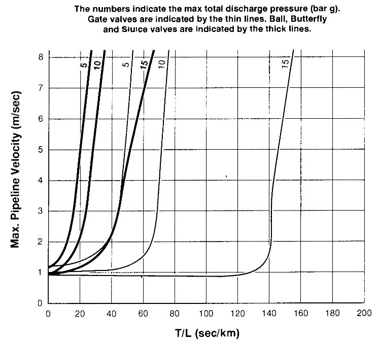
Where T = total valve closing time in seconds; L = total length of pipeline in km
This graph is only pertinent for single pipelines and single hose connections. The use of the graph should be limited to refrigerated LPG. For further detail on this aspect and on more complex systems, such as those using a number of hard-arms, a reference is available.
The graph is used in the following way. Firstly it will be noted that the horizontal axis ts labelled T/L. This is the total valve closing time in seconds divided by the pipeline length in kilometres. For the example shown below, T/L equals 30. From here a vertical line 1s drawn to cut the appropriate curve (for pressure and valve type). At this point a horizontal line is taken to read off the maximum allowable flow rate. Reference must then be made to standard documentation to convert the pipeline velocity (m/sec) Into a flow rate (m3/n).
| Example: FLOW-RATE CALCULATION (Single Line/Single Valve) | |
|---|---|
| Shore ESD valve closing time | 30 ……. (secs) |
| Shore Valve Type | ……. Ball |
| Ship ESD valve closing time | 30 ……. (secs) |
| Ship Valve Type | ……. Ball |
| Pipeline Length | 1,0 ……. (km) |
| Shore pumping pressure | 5 ……. (bar) |
| Calculated loading flow velocity | 5,5 … (m/sec) |
| Line Ø = .. 10″ .. therefore flow | 1 000 m3/h |
| Hose/Arm checked as suitable for pressure surge generation | ……. YES/ |
It is not safe nor is it practical to specify a universal minimum valve closure times for ESD valves. This is because terminals vary in design and size and accordingly the optimum closure time will depend on the actual system characteristics. It should be kept in mind however that ship’s valves are specified in the IGC Code as having a maximum closing time of 30 seconds and that this is the total time from first actuation to complete valve closure.
Discharging
Where a ship is discharging and the shore ESD valve ‘s shut against the pumping pressure, surge pressures will also develop. In this case, as the pipelines between pump and manifold are short, surge pressures should be contained by the system. However, there are two cases of ship discharge on record (See Analysis of Incidents“Appendix 1: Known Significant Accidents and Near-Miss Data (c. 1982—1994)”) which show that this is not always the case. To guard against events of this nature it is standard, during discharge, to arrange for the ship’s valve to close first.
It should be noted that when the ship’s ESD valve is activated the IGC Code requires the cargo pump to trip. This further eases the risk of high surge pressures during cargo discharge.
Pipeline Design and Maintenance
This section deals with pipelines on jetties or at off-shore moorings where submarine pipelines are used. There are two accident reports of significance in this area. One concerns the development of hydraulic hammer in a pipeline (See Analysis of Incidents“Appendix 1: Known Significant Accidents and Near-Miss Data (c. 1982—1994)”) and the other is a maintenance issue (See Analysis of Incidents“Appendix 1: Known Significant Accidents and Near-Miss Data (c. 1982—1994)”).
In the first case it was found that in certain specific circumstances, such as a sudden stoppage in the flow of LNG along the jetty pipelines, a long drain line connected to the main discharge line could empty itself of liquid. Subsequently it would refill and the refilling could happen at an accelerated pace due to hydraulic hammer. This is a pipeline design matter and suggests that the number of branches from the main line should be minimised; and certainly each should be of very limited length.
A further finding from this case (which involved a spillage) was that to limit the formation of vapour clouds, bunded areas should be fitted under vulnerable pipelines. In fact, at this terminal, this had been done and spillage to the sea was limited. If sea-spillage is allowed the heat exchange would be much greater than if the spill is contained on the jetty and larger vapour clouds would form. The need for this design precaution was well demonstrated when the spill (of about 80 m3 of liquid) was contained on the dock.
The second report deals with a maintenance issue. In this case a ship was discharging at an off-shore berth via a flexible hose and submarine pipeline. During discharge, gas was found bubbling to the sea surface forming a vapour cloud. The maintenance of submarine pipelines is a difficult task – particularly if of small diameter and of variable cross-section. Also, the working life of a submarine pipeline is notoriously difficult to predict. Problems in this respect usually surround the quality of the steel used. Poor quality steel in a salt water environment can quickly corrode due to localised electrolytic action and deep pits can form. This matter can be investigated by exterior pipe survey using divers and internal survey (if possible) by using intelligent pigs.
Also, on the question of submarine pipelines there should be a means of automatically or remotely closing the manifold valve on the sea-bed to prevent the line content escaping to the sea surface due to faulty hoses or ship break-out.
As mentioned earlier in this report it ts highly desirable for all pipelines carrying liquefied gases to be the subject of hydraulic analysis at the design stage.
A further near-miss of interest concerned the engineering of relief valves (See Analysis of Incidents“Appendix 1: Known Significant Accidents and Near-Miss Data (c. 1982—1994)”) as fitted to a hard-arm. This incident is described in Analysis of Incidents“Appendix 1: Known Significant Accidents and Near-Miss Data (c. 1982—1994)”. Here it will be noted that pumping vibrations could alter the set-pressure of the relief valve to such an extent that spillage was possible at normal cargo handling pressure.