Associated emergency shutdown (ESD) systems in the terminal are critical safety mechanisms designed to protect processes, equipment and personnel by safely stopping operations in the event of an emergency. These systems are interconnected and coordinated to ensure the shutdown process is carried out efficiently and safely at all relevant stages of the operation.
- Pneumatic ESD Link System
- Pneumatic ESD Links
- Electric Ship/Shore Link Systems
- Pyle National Electric System
- Pyle-National Electric Link Connector
- ITT-Cannon Telephone Link System
- Miyaki Electric System
- SIGTTO Electric Link System
- Fibre-Optic Ship/Shore Link System
- Radio Ship/Shore Link System
- Choice of Ship/Shore Link System
This article outlines the systems in use at liquefied gas terminals for data transfer between ship and shore, commonly known as the ship/shore link (SSL).
Pneumatic ESD Link System
The earliest ship/shore links used in LNG projects were simple pneumatic umbilical links, an air hose coupled directly into the ship’s air security system.
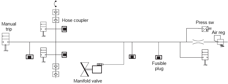
Such systems are inherently slow in operation, suffer from problems caused by dirt or moisture and it is difficult, if not impossible, to achieve accurate and repeatable timing. The designer must be aware that the diameter of the pipework and dump valve can significantly influence the closing time.
These drawbacks have led to the development of electronic ESD systems with fibreoptic or various intrinsically-safe High Voltage Systems and Safe Electrical Equipmentelectric systems providing the ship/shore link.
However, despite its disadvantages, having a pneumatic link is better than having no ESD link at all.
Details of the pneumatic link are provided below.
Pneumatic ESD Links
In the majority of terminals, pneumatic links are only now provided as a backup in the event of failure of the main optical fibre or electrical link. A typical system is shown below.
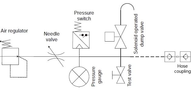
Operating pressures vary between two and seven bar, the air being supplied from shore at some installations and from the ship at others. The normal set point should be about 80 % of the supply pressure to ensure rapid tripping, commonly used is 2,7 barg supply pressure and 2,4 barg tripping pressure.
At least two types of connector are in use but the most common is the standard 1/2″ MIL-C-51234 quick connector, available from the Snap-tite «H» series, or its Nitta-Moore equivalent.
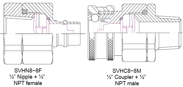
Both manufacturers using the same ordering code. A nipple is fitted to the ship’s fixed piping with the coupler fitted to the hose. The normal arrangement is for couplers at both ends of the hose so that it can be completely disconnected from the terminal’s nipple when not in use.
The first part of the number is important to ensure compatibility, the second part of the number describing the end fitting can be varied to suit the actual installation.
| Body Material | Valve or Plain | Series | Type | Size | End Fitting |
| S = stainless steel 316 | V = valve | «H» | N = nipple | 8 = 1/2″ | 8F = 1/2″ NPT female |
| C = coupler | 8M = 1/2″ NPT male |
The connectors illustrated are self-sealing to prevent dirt and seawater entering the system, but will still allow air to be dumped in the event of hose rupture. This is normally adequate although in some installations, a plain nipple is used so that air will also release in the event of manual disconnection.
Arun, Bontang and Yung An are all known to specify Snap-tite connectors, while Japanese terminals normally quote Nitta-Moore. However, either manufacturer’s product should be suitable.
One project has nipple and coupler in opposite configuration and three terminals in Japan, originally receiving LNG from Bintulu, are known to use a different connector made by Stäubli of Pfäffikon, Switzerland.
Electric Ship/Shore Link Systems
What system provided ship/shore communication?
The first intrinsically-safe electric ship/shore link was installed at the LNG stern loading berth at Lumut, Brunei, in 1972. This unique system provided both ESD-1 and ESD-2 as well as telephone signals.
It was later replaced by a fibre-optic link when the original berth was replaced by a conventional loading berth.
Pyle National Electric System
The second electric system to be used was introduced by the El Paso Corporation in 1976 for the Bethouia, Algeria to Cove Point LNG project. The cable, comprising 16 shielded pairs, was connected at each end using Pyle-National «AF» series explosionproof control connectors. This system was subsequently adopted by other terminals receiving LNG from Algeria.
These systems are primarily in use in the Atlantic Basin, Europe and Mediterranean ports but may also be found in addition to alternative systems in ports in West Africa, the Middle East and India. Up until 2009 about 70 % of all LNG carriers and 50 % of LNG terminals had systems based on the Pyle-National cable connection.
The original configuration provided for ESD-1 signals in each direction and three telephone connections, as well as continuity loops and various other signals that were peculiar to individual berths. Regrettably, there are now numerous idiosyncratic pin configurations in use at many terminals.
Details of the system, including the preferred pin configuration, are shown in the point «Pyle-National Electric Link Connector» below.
Although variations in pin configurations generally could be accommodated with dedicated ships in liner trades, Ship/shore interface for safe loading and unloading of LNG/LPGship/shore links based on the Pyle-National connector have now been adopted at over forty-five LNG terminals. It has also been adapted to suit systems on many more LNG carriers, many of which are engaged in cross-trading so, despite the efforts of one particular supplier to standardise, compatibility is becoming increasingly difficult with the burgeoning LNG trade. Without any overall control there is also the danger of insufficient regard to limiting energy in telephone connections, for example.
Pyle-National Electric Link Connector
The original cable used for the Pyle-National control connector comprised sixteen screened pairs connected as follows.
| Pyle-National Ref AF-B1716-621SL-AG (receptacle) | |||
|---|---|---|---|
| № | Pins | «Standard» | Comment |
| 1 | 01/02 | Sound powered telephone | Few terminals currently use this |
| 2 | 03/04 | Ex «ia» telephone | Dual LPG/LNG jetties |
| 3 | 05/06 | Interphone or Hotline | Uses either Iwatsu DC shift call or 48 V AC signalling |
| 4 | 07/08 | Public telephone №1 | Standard 600 ohm off hook/6 000 ohm on hook 48 V AC/80 V AC ring type |
| 5 | 09/10 | Public telephone №2 | Standard 600 ohm off hook/6 000 ohm on hook 48 V AC/80 V AC ring type |
| 6 | 11/12 | Not connected | 4 ~ 20 mA signal (vapour pressure transmitter). Used by 2 older US terminals |
| 7 | 13/14 | ESD-1 shore (export) → ship | Volt-free contact – closed when healthy |
| 8 | 15/16 | ESD-1 ship → shore | Volt-free contact – closed when healthy |
| 9 | 17/18 | Continuity loop linked on ship | Confirms to shore link connected |
| 10 | 19/20 | Spare | Some terminals use for continuity check |
| 11 | 21/22 | Not normally used | Receiving tank level high signal from shore. Not normally used |
| 12 | 23/24 | Not normally used | ESD shore – ship |
| 13 | 25/26 | Not normally used | Loading arms 1st stage |
| 14 | 27/28 | Not normally used | Loading arms 2nd stage |
| 15 | 29/30 | +24 V 35 mA ship/shore test circuit | Safe power for shore circuit test |
| 16 | 31/32 | MLM data connection | ground |
| Rx shore-ship | |||
| 33/34 | MLM data connection | Tx ship-shore | |
| Ground | |||
| 35/36 | +24 V 35 mA ship/shore test circuit | Safe power for ship circuit test | |
| 37 | Not connected | ||
History of the System and Current Developments. Vapour return during loading in Algeria for the early dedicated ships was effected by a compressor installed ashore, controlled by the ship’s vapour header pressure by means of 4 ~ 20 mA signal passed via pair №6. On these ships, contacts for the «continuity» signals, №9 (discharging) or №10 (loading), were closed by means of a shipboard selector switch, which provided confirmation of the ship’s switch status to the shore control room. In the «discharging» position, this switch also set up the ship’s system to monitor signals №11, 12, 13 and 14 – these signals only applying to the original receiving terminals in France and later Belgium and their dedicated ships.
A second, additional, Pyle-National cable is installed at the above terminals. The receptacle is a «GD» series 4-pin, 60 A power connector, believed to be for grounding. As such its use is not recommended by SIGTTO.
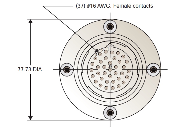
With one notable exception, all later LNG terminals that have adopted the Pyle-National ship/shore link have loosely followed this basic system, albeit with some modifications, particularly with regard to telephony. In general, the first five pairs (pins 1 to 10) have been retained as telephony channels but individual telephone instruments and their allocation to these channels has been varied to suit the particular project.
To make full use of the available pins, a number of terminals have increased the number of cores in the connecting cable to 18 pairs, generally using pins 29 to 36 for additional services such as mooring loading monitoring or environmental data.
Read also: Cargo System – Tank Construction
Fortunately, so far as ESD-1 is concerned, there is little variation and these terminals have consistently used №8 for the ship → shore ESD-1 signal. Although №7 was originally intended for the shore → ship ESD-1 signal at only LNG export terminals, practically every new terminal, import and export, has standardised on №7 for the shore → ship ESD-1 signal. Signal №12 has been retained for this purpose at the French and Belgian terminals already mentioned, while a couple of terminals and a number of ships have the flexibility to use either №7 or №12 for this purpose.
As mentioned, one LNG import terminal has adopted a completely different connection arrangement and is therefore incompatible with every other system.
SIGTTO Recommendations. To avoid over-complication and improve reliability, it is recommended that all shore initiation signals, including receiving tank high level and loading arm over-extension, are processed by the shore ESD system and passed to the ship as a single ESD-1 trip signal, not as individual signals.
For new terminals, the vapour pressure signal (№6), the «continuity» signals (№9 & 10), the receiving tank high level (№11) and loading arm over-extension (№13 & 14) are almost certainly unnecessary.
Pin connections for ship/shore ESD-1 should be standardised for all new projects as follows:
| № | Pins | Standard function | Comment |
| 7 | 13/14 | ESD-1 shore → ship | Shore presents IS-output contact – closed when healthy |
| 8 | 15/16 | ESD-1 ship → shore | Ship presents IS-output contact – closed when healthy |
As the cable and receptacles are in the hazardous area, the contact status should be detected by a suitable intrinsically-safe device, such as a switch/proximity detector interface unit to relay the signal to equipment in the safe area.
Existing LNG import terminals that use №12 (pins 23/24) to pass the ESD-1 signal to the ship should consider the practicality of duplicating this signal via №7 for compatibility with non-dedicated ships.
All ship/shore links should pass ESD-1 signals in the shore → ship as well as the ship → shore direction.
As the primary purpose of the linked system is to coordinate ship and shore ESD actions, no attempt will be made in this article to cover in detail the secondary uses, such as telephone links, or tertiary uses such as the transfer of mooring load or environmental data. SIGTTO recommendations will, therefore, be limited to the following:
At least one telephone connection should be provided to enable communications between the ship and shore control rooms. This should be connected via №3 (pins 5/6) and preferably have private line mode (also called «lift to ring», «auto-dial» or «hotdial»).
Pair №4 and №5 should be reserved for connecting other telephones.
Although the ESD signals are protected by zener barriers to limit the voltage and current to a safe level, telephone systems operating at 48 v DC and 80 v AC ring cannot be protected in this way. In some terminals, the risk of an incendive spark has been lessened by using a relay operated via the «continuity» circuit to isolate the telephone lines while the cable is being connected. However, this would not remove the risk due, say, to the cable being cut and shorting on the jetty. It is recommended that all terminals review the system in place to protect all ship/shore circuits, including telephones.
ITT-Cannon Telephone Link System
Unlike the other systems described in this section, this link does not provide ESD functionality but the description is included in the interests of completeness. The system was introduced when the export of Indonesian LNG started in 1977, and uses a MIL-STD 13 pin connector to provide telephone functions only. It was installed at the Indonesian export terminals in Bontang and Arun and LNG receiving terminals in Western Japan and Yung An, Taiwan.
As the system is not «certified safe» the shipboard connector is installed aft of the accommodation. ESD functionality was originally by pneumatic link. All the Japanese terminals have since been equipped with fibre-optic systems. See below for details.
ITT-Cannon Telephone Connector. The ship’s connection is an ITT-Cannon MR02-20-11 SF11 1 receptacle.
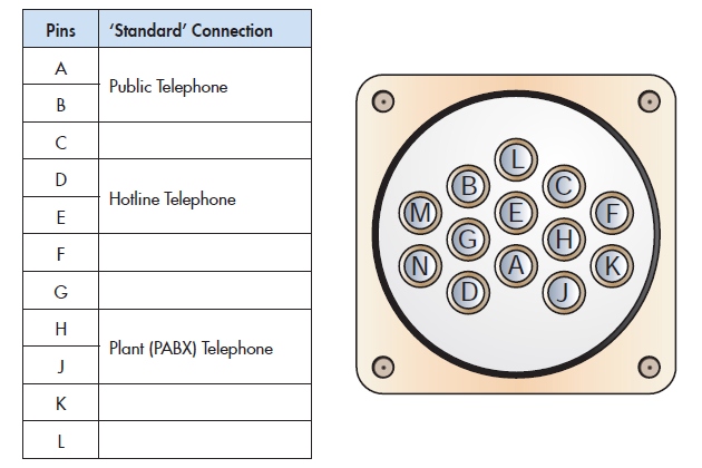
The table shows the standard configuration, although not all terminals have all three telephones.
Miyaki Electric System
This electric system was first installed at the start-up of the Malaysia LNG project in 1983. The original system, installed at the export terminal at Bintulu and the Japanese receiving terminals at Sodegaura, Higashi-Ohgishima and Futtsu, comprised of three cables each connected by a colour-coded Miyaki Denki 21-E-PT explosion-proof connector. One connector was used for ESD and the other two for telephones. The ESD link originally operated only in the ship to shore direction at the loading terminal, and in the opposite direction at the discharge terminals, but it was subsequently modified to provide signals in both directions at Bintulu and in some Japanese terminals. The fibre-optic system was later adopted as the primary ship/shore link for this project, the Miyaki link being retained only as a back-up system. In Japan, this design of ESD link is still in use for some LPG projects.
However, Miyaki Denki 21-E-PT connectors were also used when Korea began importing Indonesian LNG into Pyeong Taek in 1986. Only two cables are used in the Korean terminals and the pin configuration is different to that used for the Malaysia/Japan project. One connector provides an ESD-1 shutdown signal (shore → ship direction only), the other connector is used for telephones. See below for details.
Miyaki Denki Electric Link Connector. These connectors are manufactured by Miyaki Denki, Kameoka, Japan. In 2003, the connectors were redesigned to achieve ATEX Compliant CENELEC Eex «d» certification and the current designation is 21-EC-PT. The receptacle incorporates a switch to prevent plug insertion or removal with the receptacle «live».
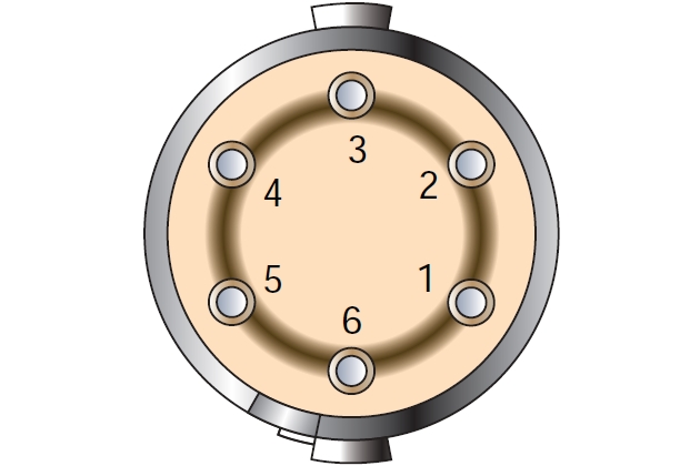
Any new projects adopting the system should follow the pin arrangement shown the table, which is compatible with the terminals in Korea and Qatar where use of the system has survived. Under this standard, only two connectors are necessary – one for ESD-1, one for telephones.
It is recommended that existing terminals using this link, should arrange for passing ESD-1 signals in both directions (not just in the shore → ship direction) so that the appropriate valves close on the shore side.
As supplied, pin 6 of receptacles are normally connected to earth (ground). This link should be removed.
| ESD-1 Connection | Pin | Telephone Connection |
| ESD-1 ship → shore | 1 | InterPhone or Hotline Telephone |
| 2 | ||
| ESD-1 shore → ship | 3 | PABX Telephone |
| 4 | ||
| 5 | Public Telephone | |
| 6 |
For information, the following table shows the connections of the three Miyaki connectors that are still in active use at some Japanese gas terminals.
| ESD-1 Connection | Pin | Telephone Connection | Interphone Connection |
| ESD-1 ship → shore | 1 | Public Telephone | L1 |
| 2 | L2 | ||
| 3 | PABX (internal) Telephone | – | |
| ESD-1 shore → ship | 4 | + | |
| 5 | |||
| 6 |
SIGTTO Electric Link System
This system was the result of a collaborative effort by SIGTTO members to produce a standardised, intrinsicallysafe delay-free ESD link using standard components. The system is available as a package from Measurement Technology Ltd (MTL), although because standard interface components are used, other manufacturers are free to produce a compatible link. The advantages of the system are that it provides an ESD-1 signal in both directions; «arming» the link requires resetting in a particular sequence. The whole system is designed and certificated to ensure its intrinsic-safety is not compromised and it incorporates features for testing and fault indication. The standard «kit» includes a pendant extension unit intended as an interim measure for use where no alternative ESD ship/shore link is available.
They are generally used in LPG and chemical gas transfer operations where many LPG carriers in the international trades are so fitted.
Although the system has been installed in a few LNG carriers to maximise spot trading advantages, none of the major international LNG projects has adopted the SIGTTO link as the primary system and, to date, the use of this system within the LNG sector has been limited to the Norwegian LNG coastal network, operating small LNG carriers. LNG projects generally require telephone signals, and sometimes other data, to be sent via the ship/shore link. While the SIGTTO link has advantages over other electric link systems in terms of assured intrinsic-safety and standardisation, the system is limited to ESD Functions and Associated Safety SystemsESD functions and is not able to pass other signals, a factor which will have effectively ruled it out as a candidate for selection by new LNG projects.
However, as only two of the five pins in the «international connector» are required for the ESD function, a pair of spare cores could be made available for other functions while still allowing compatibility with existing installations. Now that intrinsically-safe multiplexers are readily available it may be feasible to use this technology to pass a variety of data signals via the unused spare. The fibre-optic system uses a four-channel multiplexer for telephones and for exchange of mooring tension data, but as IS-multiplexers with up to 64 channels are already in use in the gas industry, the potential exists to expand the use of the SIGTTO link for telephony and data transfer. If there is sufficient support within the industry for enhancing the SIGTTO Link in this way, it should be developed as a collaborative effort to ensure that equipment and selection of data channels is standardised.
Details of the standard SIGTTO link are provided below.
SIGTTO Electric Link System. The standard shore configuration comprises:
- a terminal assembly for installing in the in the terminal’s control room, connected to;
- a jetty assembly, connected to;
- a ship/shore cable fitted with a free plug.
The standard ship configuration comprises:
- a ship assembly for installing in the in the ship’s control room, connected to;
- international fixed socket assemblies for installing in the ship’s manifold area, port and starboard.
The ship/shore cable should be twisted pair with blue coloured sheath without armour or screen (to avoid the hazard of a potentially incendive spark should the insulating sheath be cut by an earthed object on the jetty).
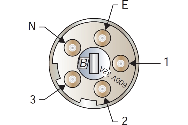
The pin designations are:
| 1 | + | Intrinsically safe circuit, nominal 24 v DC, 20 mA |
| 2 | – | Intrinsically safe circuit, nominal 24 v DC, 20 mA |
| 3 | + | Spare |
| N | – | Spare |
| E | Not connected |
Alternatively, two pairs may be connected in parallel using pins 3 & N.
In the jetty assembly two relay loops are connected back-to-back, isolating the ship and terminal ESD systems from each other as shown.
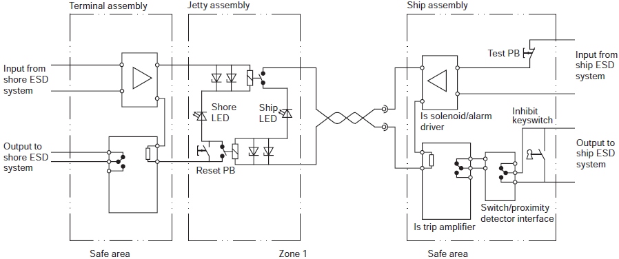
When the ship ESD system is healthy, an IS solenoid driver in the ship assembly is energised, making power available on the «ship» side of the jetty assembly via the ship/shore cable. If the terminal ESD system is also healthy, the «shore» side loop is similarly powered up and the system. Pressing the reset button in the jetty assembly will then energise the upper relay, closing its contact and energising the lower relay. The ship/shore link is then «armed». Breaking either ship or shore loops, either by breaking contacts or by physical disconnection, will cause both relays to drop out, ensuring a simultaneous linked trip.
The above diagram has been simplified for clarity. In the actual system, the terminal assembly has a separate reset pushbutton and indicators to show whether a trip was initiated by the shore or by the ship. There is also additional circuitry to allow connection of pendant units and to facilitate testing.
Fibre-Optic Ship/Shore Link System
The first optical fibre link system was developed by Sumitomo in association with Furukawa, and came into commercial use at Japanese LNG terminals in time for the start-up of the Australian North West Shelf project in 1989. A compatible system was later developed by SeaTechnik, initially to supply markets outside Japan.
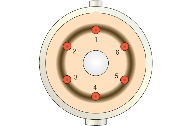
The system uses a 6-core fibre-optic cable:
- two used for an ESD-1 signal in each direction;
- two cores used with a multiplexer to provide four data channels;
- two cores spare.
One of the data channels is normally reserved for mooring load monitoring and the other three for telephones.
Compatible fibre-optic systems are used in:
- Japan,
- Korea,
- Malaysia,
- Indonesia,
- Australia,
- India,
- Middle East,
- Africa,
- UK,
- and the US.
Until 2009, about 90 % of all LNG carriers and 65 % of all Equipment and cargo system of LNG onshore terminalsLNG terminals had links based on this system. Details are provided below.
Fibre-optic Link Connector. The standard configuration of the optical fibre link is as shown in the tables.
| Core | Direction | Signal | |
| 1 | → | 4-channel multiplex data | ship to shore |
| 2 | ← | shore to ship | |
| 3 | → | ESD-1 volt free contact | ship to shore |
| 4 | ← | shore to ship | |
| 5 | → | Spare/digital SSL | ship to shore |
| 6 | ← | Spare/digital SSL | shore to ship |
| CH1 | MLM modem signal 1 200 baud |
| CH2 | Hotline telephone – Iwatsu TS3 format only supported |
| CH3 | Terminal public telephone audio signal |
| CH4 | Terminal PABX (internal) telephone audio signal |
The diagram shows the allocation of fibres for the connector.
A test plug is usually provided that has internal loops to return the ship-to-shore signals back to the relevant receiver. It is used in conjunction with the test button to prove the circuits, including the cables to each shipside or jetty connector. The test plug must not be left permanently connected.
Radio Ship/Shore Link System
The original ship/shore link at Withnell Bay LNG Terminal comprised two radio links, one for ESD and one for telecommunications. The system provided the same functionality as the fibre-optic system already installed on the dedicated North West Shelf ships. Both radio systems proved unreliable and, eventually, were un-maintainable. The system was abandoned and replaced by a SeaTechnik fibre-optic link system in 2003.
Radio ship/shore ESD links are generally considered unsuitable for the following reasons:
- Radio regulatory regimes differ considerably around the world and the continuing commercial demand for bandwidth require existing allocations to change from time to time, often at short notice.
- The unlicensed low-power UHF bandwidths in the 430 MHz region have very limited bandwidth for other than ESD signals and the rapid growth of simple commercial and domestic applications leads to failures due to local interference. This is less of a problem in remote desert export terminal areas than for the import terminals which are often located in industrialised and populous areas.
- The presently unregulated UHF bandwidths in the 2,4 GHz region have much wider bandwidth capability but the demands on bandwidth for both simple and complex applications, such as WiFi radio LAN networks, are growing exponentially.
- The duplex (bi-directional) ESD has to be fail-safe but with a response time of 500 ms or less. The consequences of a spurious trip are commercially and operationally severe particularly for LNG transfers.
Choice of Ship/Shore Link System
Generally, the LNG industry uses fibre-optic and/or electric link systems. At one time the split was roughly geographical, with the Pyle-National electric being the usual choice in the Atlantic basin and fibre-optic systems being the most popular in the Pacific. However, with the expansion of the industry and ships engaged in cross-trading, this rule is no longer valid as some LNG terminals in the Atlantic region have installed fibre-optic systems, while Pyle-National electric systems have been installed at a few terminals in the eastern hemisphere. The decision to fit both fibre-optic and electric systems is generally a commercial matter to enhance the flexibility of the terminal when dealing with vessels on spot trades.
It will be interesting: Hazards of LNG and Relevant Gases
While the fibre-optic system has a standard pin-configuration this is not true for electric links, particularly the Pyle-National connector. Ideally, all terminals using the Pyle-National should agree a standardised pin-configuration but, given the difficulty of arranging this with ships already in service, this is probably unrealistic. However, for new terminals, care should be taken to ensure that no further variations are introduced by adopting the pin-out.
The LNG industry generally uses the pneumatic link as a back up to the primary ship/shore link.
In the LPG & chemical gas industry the most popular system is the SIGTTO link, which is the de-facto standard for many of the larger LPG carriers. This sometimes causes problems at export terminals with dual purpose jetties capable of accommodating both LNG and LPG carriers, as these terminals often only have an LNG type of link system. It is recommended that consideration be given to providing a standard SIGTTO link at these berths for use when LPG is loaded.
