Discover essential insights into emergency shut-down and release systems in our comprehensive guide. This article covers critical components such as ESD valves, pendant controls, and break-away couplings for small ship operations.
In this section discussion covers methods of spill limitation at the ship/shore connection and accidents associated with them Accordingly, the following nomenclature is relevant.
- ESD – Emergency Shut-Down system and valves (fittings on ship and shore);
- BAC – Break-Away Coupling (often fitted for hoses at the shore manifold);
- ERS – Emergency Release System (an emergency control system for hard-arms). The ERS includes an ESD link between ship and shore for exchanging shut-down information);
- ERC – Emergency Release Coupling (fitted for the dry-break of hard-arms).
The foregoing systems provide ESD in case of emergencies (such as spills and fires) and the ERC (or BAC) provide dry-break facilities for cases of ship break-out.
Debate surrounding these systems recognises that the most vulnerable point in a ship/shore piping system is the cargo hose or hard-arm. Either type of cargo transfer connection may be put at risk from a variety of causes but ship break-out, fire, spillage and over-pressurisation are central.
These devices take two forms. Firstly, ship manifolds are always outfitted with an ESD system and ESD valves. At terminals this should also be the case – but in some smaller depots such safety may not yet be available – it is recommended. ESD valves are provided to ensure a controlled stop (quick and safe) in emergency situations such as serious leakage (see listing in Emergency Shut-Down and Emergency Release“Larger Terminals”). It should be possible for this action to be initiated manually (from a remote position) and automatically. Secondly, a form of dry-break coupling is often fitted as a spill precaution against ship break-out when the primary defence of good moorings has failed (see Accident Prevention The Use of Hoses & Hard-Arms at Marine Terminals Handling Liquefied Gas“Safe Berths, Mooring & Operating Procedures”).
For LNG and most LPG refrigerated trades, the Loading Arms (Hard-Arms) – Specifications, Operation, and Maintenanceuse of hard-arms’s standard Arms should be guarded with Emergency Release Systems (ERSs). This is a development continually encouraged by SIGTTO. Incorporated in the ERS is a quick acting Emergency Release Coupling (ERC) which, in the event of accident, limits spillage to very small quantities – so restricting vapour cloud formation. This study found that a number of serious accidents plus some minor spillages and near-misses occurred with ERS systems and ERC couplings. The problems concern design, operation and maintenance.
As discussed in Accident Prevention The Use of Hoses & Hard-Arms at Marine Terminals Handling Liquefied Gas“Safe Berths, Mooring & Operating Procedures” it is clear that wind, current and even ice-floes can cause a ship to break-out from its berth. Incidents of this nature happen on a world-wide basis. Furthermore, gas carrier break-outs can be caused by the interactive effects of other ships manoeuvring at close range. These are the main reasons why an ERC should be fitted to hard-arms and a BAC should often be fitted at shore manifolds when hoses are in use.
The various emergency methods developed for stopping cargo flow (say, in the case of leakage or fire) and allowing safe dry-break of the cargo connection (say, in the case of ship break-out) are described below.
Small Terminals
The following notes are general in nature but are aimed as a guide to safe operations at small terminals. Some of the comment, and particularly that on ESD valves will be generally applicable to all terminals and ships.
Emergency Shut-down Valves
The IGC Code details the requirements for gas carrier manifolds and here it will be found that all shipboard manifolds must be fitted with a valve of appropriate ESD design. The valve must be capable of remote operation and there are various stations on board from where remote actuation can be manually initiated. In addition, valve operation should be triggered by automatic means which depends upon sensors detecting emergency conditions.
It is recommended that shore manifolds be outfitted in a similar way to that described above and that shore ESD valve manual trips to be positioned appropriately on the jetty.
From the foregoing description it will be noted that there are separate emergency shut-down systems on board ship and ashore operated by the separate crews. In an emergency each system is operated independently by each crew or by separate sensors. The valves themselves are usually operated by pneumatic or hydraulic means and have adjustable closing times. In an emergency such as a fire, the ESD valves on ship and shore can be closed from safe locations. In this way pumps should be stopped and valves are closed at a controlled pace without causing further problems.
Even for the smaller terminals, as described in this section, the guiding rules for a sale emergency shut-down should still be observed – see Emergency Shut-Down and Emergency Release“Larger Terminals”.
The basic controls described above are normally found only in small terminals where hose is used for cargo transfer and where the risk associated with surge pressures are minima. In larger terminals these systems should be enhanced by interlinking ship and shore systems – see Emergency Shut-Down and Emergency Release“Larger Terminals” and Emergency Shut-Down and Emergency Release“Refrigerated Terminals”.
Pendant Controls
An improvement on the above basic system ts the fitting of pendant controls (having long wandering leads) to allow cross-control. By this means the shore ESD can be controlled from the ship or vice versa. Pendant-controls may be supplied from the jetty to the ship (usual for loading); in which case the ship has a stop control over shore pumps and valves.
Also, in the case of ship discharge, a pendant may be supplied by the ship to jetty personnel: so giving the shore crew emergency control over the ship’s valves and pumps. This allows for a better control during emergency Stops in as much as the pumping party can shut-down both ship and shore in the correct sequence.
Break-away Coupling – Small Ship Operations
In themselves, the systems described in Emergency Shut-Down and Emergency Release“Emergency Shut-Down Valves” and Emergency Shut-Down and Emergency Release“Pendant Controls” above, are insufficient ta protect small terminals (and small ships) from sudden break-out. The consequences of a ship breaking-out can be severe and, in the oil trade, there are cases on record of the shore manifold being fractured on break-out with the emptying of ail pipeline contents. Even for small ships, these cases have involved massive fires. Such situations probably also happen in the gas trades. Without some form of auto-shut-down, the initial response to a break-out will depend very much on the whereabouts of each crew-member when the emergency strikes. A method of guarding against shore manifold damage is by means of a BAC. A photograph of this type of equipment is shown here (Fig. 1).
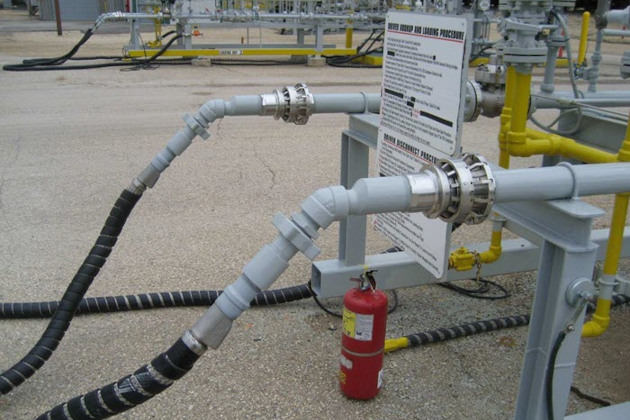
Other types of BAC are in use. These include ERC systems similar to that described in Emergency Shut-Down and Emergency Release“Emergency Release Coupling”. In this case the BAC is operated by breakage of a pneumatic pipe or small wire rope which is securely connect between ship and shore. If the ship moves outside of the radius suited to the length of these lines then they fracture and the valves on the ERC are activated. This system is used on the river Rhine and has an advantage over the older system (as shown in the photograph) in that the hose is not over-strained as part of the release operation.
Although the need for a BAC is not apparent from the accident statistics reproduced in Analysis of Incidents“Appendix 1: Known Significant Accidents and Near-Miss Data (c. 1982—1994)”, it is SIGTTO’s view that some accidents of this type occur during small ship operations which remain unrecorded. At terminals using hoses, the need for fitting a BAC should be assessed by the plant management based on an overview of the risks at the berth such as mooring adequacy, angled currents and passing traffic.
Of course the BAC operates quickly and accordingly, may cause a pressure surge. However, in the smaller terminals having tanks near to the jetty and slower pumping rates (in the order of 100 tonnes/hour), a surge is unlikely to be excessive. This is especially so if pipe standards to Class ASTM 300 lb are fitted. But in any case, at such times, the need for quick closure may take precedence over a desire to limit pipeline damage due to surge pressures.
BACs can be manufactured to operate on the principle of shear pins fracturing as a result of an angled pull on the hose. This necessitates the shore manifold to be very firmly held in place in a strong mounting. It should also be kept in mind that the BAC will be specified against a specific hose type (and intrinsic strength). Therefore to operate satisfactorily the correct hose always must be used. To fit anything smaller may result in the nose failing before the shear pins fracture.
For ship/shore operations involving the use of cargo hoses, a break-away coupling is recommended.
Larger Terminals
The problems associated with translating small snip practices into the larger operations are described below. In essence, the main issue is the safe control of ESD in order to ensure a quick shut-down.
These extra problems concern flow rate and surge pressure and for this reason study of Pipelines in Marine Terminals: Key Considerations for Handling Liquefied Gas“Understanding Liquefied Gas Pipelines in Marine Terminals” is also essential.
Linked ESD Systems
Guiding rules to limit pressure surge are:
- To stop the pump;
- First close the ESD valve nearest to the pump;
- Finally close other ESD valves.
This is a procedure recognising the greater vulnerability of the ship/shore connection due to surge pressures. However, it should be noted that the procedure only addresses ESD and not the ERS or ERC: such systems are automated from the shore alone and, accordingly, wiring within the ship/shore link is unnecessary for automatic release purposes.
As will be noted, the guiding rules are standard but the operational sequence will depend on whether the ship is loading or discharging. Accordingly, it will also be recognised, that to follow the protocol in a satisfactory manner, much co-ordination is required between the ship and jetty. It is accepted that in an emergency situation such control is difficult and for this reason a linked ship/shore Emergency Shutdown System (ESDS) on Liquefied Gas CarriersESD system (which will always follow the correct protocol) is strongly recommended. This must be engineered to ensure an appropriate procedure (no matter which party initiates an ESD). This system has the advantage of being quite easily retro-fitted to existing plant and ships. It is ideally suited to the many berths not so fitted in the LPG trade.
The following information outlines the manual and automatic means by which an ESD should be activated: furthermore it outlines the signals which should be transmitted. This data ts reproduced in abbreviated format from a SIGTTO Panel Paper which covered questions mainly relating to the LNG trade.
An ESD trip should be initiated by the following EMERGENCIES. It is possible that not all these links will be designed into a system handling LPG:
| SHIP | TERMINAL |
|---|---|
| Manual Trip | |
| Operation of manual trip | Operation of manual trip |
| Automatic Trip | |
| Shut-down signal from ashore | Shut-down signal from ship |
| Overfilling of any cargo tank | Overfilling of receiving tank |
| Power loss to valve controls | Power loss to arm manoeuvring |
| Loss of control air pressure | Power loss to ERS |
| ESD valve moving from full-open | ESD logic failure |
| ESD logic failure | Fire in terminal area |
| Fire in cargo area | Loss of electric power |
| Loss of electric power | Ship movement – pre-ERS |
| Activation of the ERC | |
| High level in Surge Drum | |
ESD should initiate the following IMMEDIATE ACTIONS:
| ON SHIP | ON TERMINAL (LOADING) |
|---|---|
| Send shut-down signal to the shore | Send shut-down signal to the ship |
| Trip loading pump | |
| Trip ship’s cargo and spray pumps | Open spill-back valves |
| Start to close shore ESD valve | |
| Trip booster pump (LPG) | ON TERMINAL (RECEIVING) |
| Trip vapour return compressor | Send shut-down signal to the ship |
| Start to close ship’s ESD valve | Start to close shore ESD valve |
The foregoing information begins to become important for the larger ships covered tn this section and the procedures described continue to be of relevance throughout section below which follows.
Refrigerated Terminals
For LNG and most LPG refrigerated trades, the use of hard-arms is a world-wide standard. The arms should be fitted with Emergency Release Systems (ERSs) and should normally include ERCs. This is a development continually encouraged by SIGTTO. The development of the modern ERS system is relatively new and fitting/retro-fitting has become standard at many terminals in many countries. Progress has become common since about 1989.
The ERS has two functions:
- It controls the ESD protocol (sometimes called the ESD/1 control) and;
- It activates the ERC (sometimes known as the ESD/2 control).
Here the reader ts referred back to Emergency Shut-Down and Emergency Release“Larger Terminals”. An essential part of the ERS system is an ESD Link for exchanging shut-down information between ship and shore.
Incorporated in the ERS ts the quick acting Emergency Release Coupling (ERC) which, in the event of accident, limits spillage to very small quantities (less than 60 litres). Hard-arms fitted with such safety equipment are complicated devices. As mentioned earlier, this study found that a number of serious accidents plus some minor spillages and near-misses occurred with these devices. The problems concern design, operation and maintenance.
Emergency Release Systems (ERS)
As will be seen from Analysis of Incidents“Appendix 1: Known Significant Accidents and Near-Miss Data (c. 1982—1994)”, the majority of accident reports with ERS systems are attributed to malfunction or incorrect assembly of hard-arm hydraulic systems, however, some have been attributed to electrical faults. It is also of note that most incidents involved first generation (circa 1974) equipment. In newer equipment, sequencing systems have been introduced and interlocks are now specified which will not allow ERCs to release without the valves on either side being closed.
Read also: Comprehensive Overview of LNG and LPG Cargo Hoses in STS Operations
In addition to the above there are some important maintenance aspects regarding ERS systems. Firstly, the manufactured tolerances of hydraulic oil systems on the arm are such that they require good system cleanliness. Accordingly, the removal of debris, by filtration or centrifuging, is essential Secondly, hard-arm manufacturers impose strict specifications on the quality of the hydraulic oil to be used. The use of alternative oils must be avoided.
The ESD Link
ESD Links (see also Emergency Shut-Down and Emergency Release“Larger Terminals”) are very well established in the LNG trade but much less so in LPG. In the early LNG projects ship and shore were coupled with pneumatic systems. These could be slow in operation and suffered from problems with dirt and moisture. These drawbacks led to the development of electric or electronic and optical links. Accordingly there are now four main types in operation:
- Pneumatic types;
- The intrinsically safe (or increased safety) type;
- The fibre optic type, or;
- Those operated by radio telemetry.
With regard to the use of radio telemetry some authorities are satisfied that it can operate satisfactorily but others are not. Questions on the suitability of such equipment are based on the possibility of radio interference.
When LNG ships are used in cross-trading the multiplicity of systems introduces difficulties. However, the problem does not stop the four systems described above. For the pneumatic variety there are three variants involving the use of different plugs. For the intrinsically safe variety there are five variants. But for both the optical fibres and radio types, so far no variants have been developed Accordingly there are ten different possibilities in the LNG trade for ship/shore linkage.
Prior to receiving a new ship at an Linked ESD Systems at Both LNG and LPG TerminalsLNG terminal it is therefore vital that prior communication covers the question of the correct system being fitted on the ship.
Emergency Release Couplings
An ERC is a dry-break coupling fitted in the ship-side portion of the hard-arm (Fig. 2).
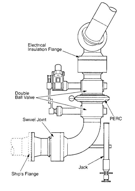
The ERC arrangement is fitted within the lower section of the articulated arm and consists of a hydraulically controlled coupling which, in normal operation, is held clamped together. This coupling is flanked (above and below) by hydraulically operated valves In the event of a near break-out, the two valves close first within 5 seconds. This action ts closely followed by the release of the clamped coupling which takes place within 2 seconds. However, at the design stage, this fast action must be reviewed against potential high pressure surges resulting from rapid closure.
It is essential, in the case of a break-out involving a fast-moving ship, that the ERC operates before a ship has reached the limit of the operating envelope. Sometimes timed release systems have not achieved this objective (See Analysis of Incidents“Appendix 1: Known Significant Accidents and Near-Miss Data (c. 1982—1994)”).
After release, the lower ball valve remains attached to the ship’s manifold and the arm, with upper valve attached, rises clear of the ship. The method by which the outer arm rises clear of the ship can be specified and this could assist in limiting accidents (See Analysis of Incidents“Appendix 1: Known Significant Accidents and Near-Miss Data (c. 1982—1994)”).
A number of accidents reports continue to attest to inexplicable ERC valve closures during cargo pumping (fortunately it now seems that the interconnection of valve operation and ERC release is avoiding spillage). However, when the flanking ball-valves close in this way, pipelines are put under shock load unnecessarily and obviously this should be avoided. The problems which have occurred point to design or maintenance on the control systems as being at fault.