Both LNG carriers (LNGCs) and conventional tankers often utilize high tensile steel construction for their hulls and structural components. High tensile steel offers superior strength-to-weight ratio, allowing for lighter and more efficient vessel designs while maintaining structural integrity and safety standards. In LNG carriers, where cargo containment and insulation systems add significant weight, high tensile steel construction helps optimize the overall weight distribution, enhancing stability and fuel efficiency. Similarly, in conventional tankers, high tensile steel construction enables the vessels to withstand the harsh marine environment and dynamic loads experienced during cargo operations while maximizing cargo carrying capacity. Overall, the use of high tensile steel construction in both LNG carriers and tankers underscores its importance in achieving optimal performance, durability, and safety in maritime transportation.
In LNG carriers (LNGCs), maintaining optimal hull temperature is essential for ensuring the structural integrity and safety of the vessel. The hull structure, typically constructed from high tensile steel, plays a critical role in withstanding the extreme conditions encountered during LNG transportation. High tensile steel offers superior strength and durability, enabling the hull to withstand the cryogenic temperatures of LNG cargo without compromising its structural integrity. Additionally, the use of high tensile steel in LNGC construction allows for lighter vessel designs, optimizing fuel efficiency and reducing emissions. By carefully managing hull temperature and utilizing high tensile steel cargo containment systems, LNG carriers can safely and efficiently transport liquefied natural gas across vast distances, meeting the global demand for clean energy while adhering to stringent safety standards.
Difference Between LNGC’s and Tankers
It has been often stated that there is no substantial difference between a LNGC and another type of ship, for instance a tanker, from the point of view of the hull construction. This is true from a certain point of view: steel cutting, steel welding, block construction and erection, are mainly the same as for other types of ships. However, there are certain differences between a LNGC and a tanker of similar capacity. Table 1 indicates the main characteristics of a tanker of 150 000 DWT and a membrane LNGC of 145 000 m3 built by the same shipyard. Both ships carry a comparable volume of liquid cargo; their total hold volume is therefore almost the same.
| Table 1. Comparison between a tanker and a LNGC | |||
|---|---|---|---|
| DIMENSIONS | 145 000 m3 LNGC | 151 000 DWT TANKER | VARIATION |
| Lengthscantling(L) | 266,06 m | 260,93 m | +1,95 % |
| LengthBP | 270,00 m | 264,00 | +2,22 % |
| Breadth (B) | 43,40 m | 48,00 m | -10,60 % |
| Depth (to main deck) (D) | 26,00 m | 23,60 m | +10,17 % |
| Depth (to top of trunk) (DT) | 32,80 m | No trunk fitted (23,60 m) | +38,98 % |
| Draft (d) | 11,40 m | 15,30 m | -34,21 % |
| Freeboard | 14,60 m | 8,30 m | +75,90 % |
| Block coefficient | 0,7762 | 0,833 | -8,7 % |
| Number of cargo tanks | 4 | 12 plus 2 slop tanks | |
| Length of cargo area | 174,82 m | 213,20 m | -21,95 % |
| Max. width of tank | 38,33 m | 21,55 m | +77,86 % |
| Max. length of tank | 45,475 m | 33,60 m | +35,34 % |
| Max. volume of tank | 46,775 m3 | 15,215 m3 | +307,42 % |
| Still water bending moment (hogging) | 333,500 tm | 308,000 tm | +8,28 % |
| Still water bending moment (sagging) | 156,000 tm | 228,000 tm | -46,15 % |
| L/B | 6,13 | 5,44 | +12,68 % |
| L/D (L/Dт) | 10,23 (8,11) | 11,05 | -7,28 % (-36,25 %) |
| B/D (B/Dт) | 1,67 (1,32) | 2,04 | -22,15 % (-54,54 %) |
| d/D (d/Dт) | 0,438 (0,35) | 0,65 | -14,84 (-87,51) |
| d/L | 0,043 | 0,059 | -37,21 % |
| Cargo area length / L | 0,66 | 0,82 | -24,24 % |
The differences of design of the two ships are mainly due to two facts: the first is that while the total cargo volume of the two ships is almost equal, the total weight of the cargo of the LNGC is about ½ of the total weight of the oil. The second is the necessity to reduce, as much as possible, the number of Cargo System – Tank Constructioncargo tanks in the LNGC and to give them a geometrical shape as simple and smooth as possible to properly install the insulation and to limit the production of boil-off.
Figure 1 gives a visual idea of the differences between the two ships.
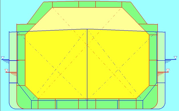
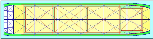
The simplified midship section of the LNGC drawn in red is superimposed to the simplified midship section of the tanker drawn in blue. Figure 2 shows the arrangement of the cargo tanks in the two ships.
From table 1 and the Figures 1 and 2, the following main characteristics of a LNGC with respect to a normal tanker are obvious.
The LNGC is a ship of unusual depth and very low draft, rather narrow with respect to an ordinary tanker. A membrane LNGC has a complete double hull extended to the deck (double hull tanker does not include the deck). However, the longitudinal centerline bulkhead, some times arranged in the tanker is missing. The volume of the tanks of the LNGC is huge compared with that of the tanker. As the two ships have comparable dimensions and block coefficient, the Still Water Bending Moment is comparable, however the Section Modulus of the LNGC is higher than that of the tanker, due to the increased height of the hull, and the existence of the double deck. However, for membrane ships, the designer of the insulation system imposes some limitation on the allowable longitudinal stress at the level of the inner deck in order not overstress the membrane.
Hull Temperatures and Materials Selections
Hull Temperature
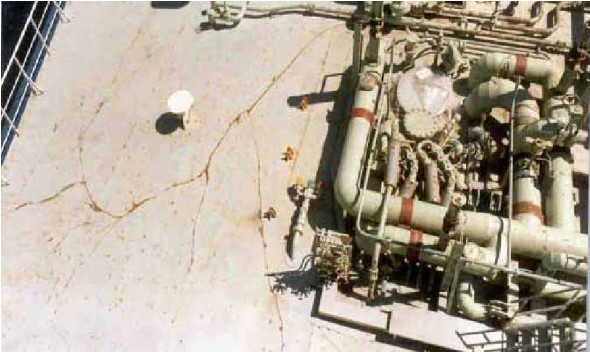
In general the materials used for the construction of the hulls of LNGC are the same used for the construction of other types of ships. However, the selection of material grade is of the utmost importance for this type of ships. In fact, steel at low temperature crystallizes and becomes subject of brittle fractures. This is why the design of a LNGC has to be very accurate to prevent the risk that the cargo, at the temperature -163 °C may leak on the hull structures and cause fractures. This highly undesirable event would lead to crack the hull in very short time and to its complete loss if no proper measures are immediately taken. Figure 3 shows how a brittle fracture due to cold propagates in the deck of a ship.
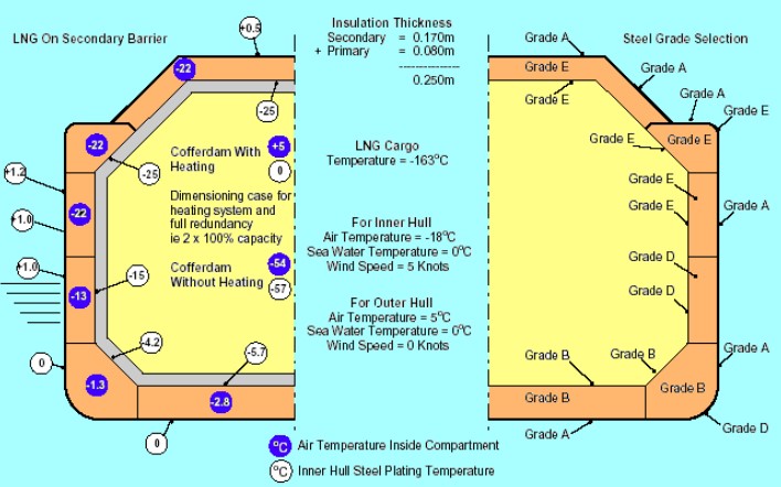
However, no matter how effective is the insulation of the tanks, a certain amount of heat is transmitted through the tank boundaries, so that the actual temperature of the steel structures surrounding the tanks will be at a temperature intermediate between that of the external environment (sea and air temperature) and that of the outer surface of the tank insulation. For this reason, one of the first steps of the design of a LNG is to calculate the temperatures of the various plates of the hull structure assuming to have lost the primary barrier, i. e., assuming that cargo at its very low temperature is in the interbarrier space (nearest to the inner hull structure) and the design external environmental temperatures contemplated by the applicable regulation. As USCG regulations are more severe than those of Origin, Applicability, Requirement of IMO Gas CodeIMO IGC Code, all gas carriers are designed using the USCG environmental temperatures, as no owner of such an expensive ship can preclude future possibility to enter US ports just because less severe environmental conditions have been used for the material selection.
The USCG environmental design conditions (CFR 46 Part 154.170) are those indicated in Table 2:
| Table 2. USCG environmental conditions | ||
|---|---|---|
| HULL STRUCTURE | AIR | SEA |
| Outer hull | +5 °C | +0 °C |
| Longitudinal structures contiguous to cargo containment system with secondary barrier in all the world except Alaskan waters. | -18 °C Air speed 5 knots | +0 °C |
| Longitudinal structures contiguous to cargo containment system with secondary barrier in Alaskan waters. | -29 °C Air speed 5 knots | -2 °C |
For the calculation of the design temperatures of the various plates forming the hull and the inner hull envelope, it is to be taken into account the gradient of temperature between the temperature of the cargo and the environmental temperatures stated in Table 2. See Figure 4.
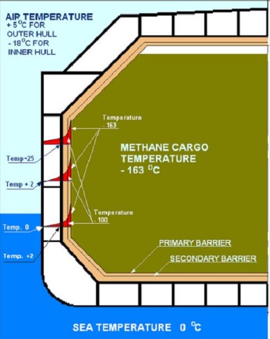
Figure 5 indicates in the left side the temperatures of the various longitudinal portions of a membrane LNGC calculated taking into account the above environmental conditions.
Material Selection
Most metals lose their ductility at very low temperatures; LNG may cause the brittle fracture of many materials. In case of LNG spillage on the ship’s structures, the high thermal stresses generated from the restricted possibilities of contraction of the plating result in the fracture of the steel. Thicker plates are more fragile than thin plates of the same material.
A brittle fracture is even more dangerous considering that once a crack starts, it has a tendency to go on, extending its length like a zipper opening, until a crack arrestor is found. The less ductile the steel (more fragile), the faster a crack propagates (see Figure 3).
Ductility, as a measure of steel resistance to fracture, is tested using an impact test, such as Charpy V-notch test. During this test, the lower the test temperature used with steel exhibiting acceptable notch toughness, the greater is the “ductility” the steel possesses. Ductile steels are less subject to brittle fractures and in case a fracture happens, they offer a certain resistance to crack propagation. For this reason steels of higher ductility are used as crack arrestors in the high stressed areas of ships, such as, sheer strakes, deck stringer plates, turns of bilge, etc. and whenever there are critical high stressed structures, or structures permanently exposed to cold conditions.
According with Training LNGC Course for ABS and Service Project Managers & Project Management OG LNGC Project in KoreaABS Rules, the following ordinary strength hull structural steel grades are considered:
1) GRADE A steel.
Is the most common grade used in ship building for its good weldability and ductility properties. Impact test is not required when the steel is produced using a fine grain practice and normalized, unless the thickness is over 50 mm. In this case the impact test is to be carried out at ambient temperature.
2) GRADE B steel:
- has improved ductility;
- Impact test are carried out at 0 °C (32 °F).
3) GRADE D steel:
- has still greater ductile properties;
- Impact test is carried out at -20 °C (4 °F).
4) GRADE E steel:
- possesses excellent ductile properties;
- Impact test is carried our at -40 °C (-10 °F).
ABS Rules also consider high tensile steels of grade AH, DH and EH, which have ductility characteristics similar to those of ordinary steels Grade A, D and E.
The selection of the hull material is also based on the USCG requirements, as indicated in Tables 3, 4.
| Table 3. USCG requirements on steel grades (outer hull) | |
|---|---|
| OUTER HULL | |
| Structure | Steel grade |
| Deck stringer plate | E |
| Sheer strake | E |
| Turn of bilge | E or D |
| Other structures at temperature of -5 °C and over | As per ABS Rules |
| Other structures at temperature below -5 °C | As structures contiguous to cargo containment system |
The right part of Figure 4 indicates the grades of the materials selected for the various locations of the ships structures based on the results of the temperature calculations, taking into account the USCG requirements.
| Table 4. USCG requirements on steel grades (inner hull) | ||
|---|---|---|
| STRUCTURES CONTIGUOUS TO CARGO CONTAINMENT SYSTEM (INNER HULL) | ||
| Minimum Temperature | Steel Thickness | Steel Grade |
| 0 °C and below, but over -10 °C | All | As per ABS Rules |
| 10 °C and below, but over -25 °C | T ≤ 12,5 mm | B |
| 12,5 mm < T ≤ 25,5 mm | D | |
| T > 22,5 mm | E | |
| -25 °C and below | T ≤ 12,5 mm | D |
| T > 12,5 mm | E | |
In the case of LNGC, it is very important that the surveyor diligently verifies that the correct grade of steel is used in the proper locations, commencing from the construction of the first blocks, as this is one of the major issue of the design of an LNGC.
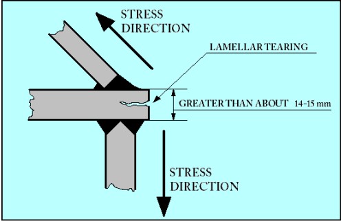
In addition to the normal material grades A, B, D and E, it is possible that in certain particular locations grade “Z” material is used. This material has improved “through thickness” characteristics. In fact, even ductile plates subjected to high forces perpendicular to their surface can crack. This phenomenon, called “lamellar tearing” is clear as shown in Figure 6.
It is therefore very important that a surveyor is well acquainted with the hull design and the locations of steel grades of higher ductility at lower temperatures and those of improved “through thickness” properties. Additionally, these areas will most likely be included in construction monitoring plan (SHCM).
Particular attention is to be paid when surveying the inner hull structures of the membrane type LNGC. While carrying out these inspections the surveyor must bear in mind that these structures are going to be covered by insulation, and that one side will be not accessible for inspection during the entire ship life.
The exact location of a crack in an insulated boundary is not easy to find. Even limited cracks, that might be not harmful for the life of a regular ship, are critical for a membrane LNGC.Even a small leak of LNG is extremely dangerous as it can affect the whole strength of the ship.
Finally, repairs of the inner hull are very expensive, as they require a long series of expensive and time consuming operations, such as discharging, inerting, warming-up, dismantling part of the membranes and of the insulation in way of the damage, and then again the reinstallation of the insulation and membranes, their testing, the cool down, etc. Even the smallest repairs, for instance just half-an-hour of workmanship, will require this very long and expensive procedure. Moreover, these repairs cannot be delayed. A LNGC tank with a leak is to be immediately taken out of service until a repair has been completed. If a leak is detected during navigation, the safety procedures of the existing LNGC require the immediate flooding of the adjacent compartments to the leaking tank so as to the temperature, as first step, and the quick elimination of the cargo of the tank through jettison or other means, as second step. This means that even a minor damage to another type of vessel may causes at least the loss of ¼ of the LNGC’s cargo.
Use of High Tensile Steels
High tensile steels (HT) offer several advantages over mild steels in vessel design and construction. These advantages, however, do not readily translate into the complex design of an LNGC. Based on this, some owners do not accept designs with significant amount of high tensile steel for the following reason.
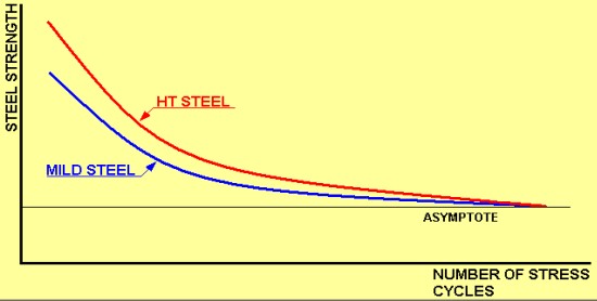
All steels, whether mild or high tensile, loose a portion of their original strength due to both pulsating and alternating stresses induced by the different loading conditions and vessel movement in a seaway. It has been demonstrated that both mild steel and high tensile steel are affected similarly by this strength reduction and, after a certain time, the residual strength of both the steels approach the same asymptotic line.
The position of the asymptote line depends on whether the stress is pulsating or alternate; the magnitude of the variation of stresses, type of cycles, etc. (in other words, on the history of stress variations during the ship life). The position of the asymptote line is the same for mild steel and high tensile steel (see Figure 7) subjected to the same stress range variations.
Based on this, in an area subject to fatigue stress, after a number of years, there is no difference, as far as the material strength is concerned between mild steel and HT steel. However, since HT steel was originally adopted to reduce the weight, being this equivalent to say to reduce thickness, taking the advantage of its higher strength. Once the advantage of the higher strength is lost, there remains the thinner thickness that might be not sufficient to withstand the imposed loads.
This phenomenon was largely underestimated in the late sixties and seventies, when HT steel was used largely to reduce the weight of ships, which dimensions were increasing and increasing. Eventually, this underestimation led to a great number of cracks, casualties and shorter life of the ships.