Ensuring high voltage safety in LNG environments is critical due to the heightened risk of electrical hazards associated with the transportation and processing of liquefied natural gas.
- Feature of High Voltage Systems
- Coordination of Breakers Between Generator and Loads for Short Circuit
- Main Bus Bars
- Large Motors Applications and Volume of Cables in Cable Ways
- Additional Featurs
- Space
- Additional Advantages and Disadvantages of HV Systems Versus LV Systems
- Safety Features in High Voltage Systems
- Rotating Machines
- Switchgears and Control-Gear Assembly
- Power Transformers
- HV Cable Installation
- Additional Miccellaneous Recommendations
Key protective features include advanced insulation technologies and automated safety shutdowns, which are essential for maintaining operational integrity and safeguarding personnel in these high-voltage settings.
Feature of High Voltage Systems
Coordination of Breakers Between Generator and Loads for Short Circuit
Coordination of circuit breakers between generators and users for short circuit is easier in Reasons for Choosing High Voltage in Planning Power Systems for LNG Plantsthe high voltage systems. This is an advantage of the high voltage systems versus the low voltage systems.
Main Bus Bars
As power demand increases, main bus bars should be split, which is more easily accomplished in high volatage systems. In particular, the two sections are physically separated and located in different compartments, this is one advantage of high voltage systems versus low voltage systems.
Large Motors Applications and Volume of Cables in Cable Ways
For large motor applications, (e. g. bow thrusters, ballast pumps, cargo pumps), high voltage systems give the following advantages:
- Reduction of rated current.
- Reduction of the required volume of cables.
- Reduction in size of motors.
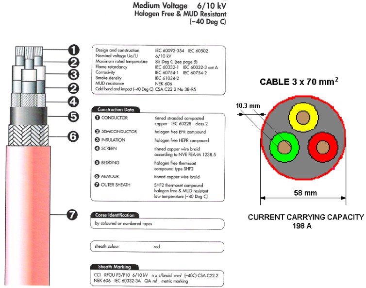
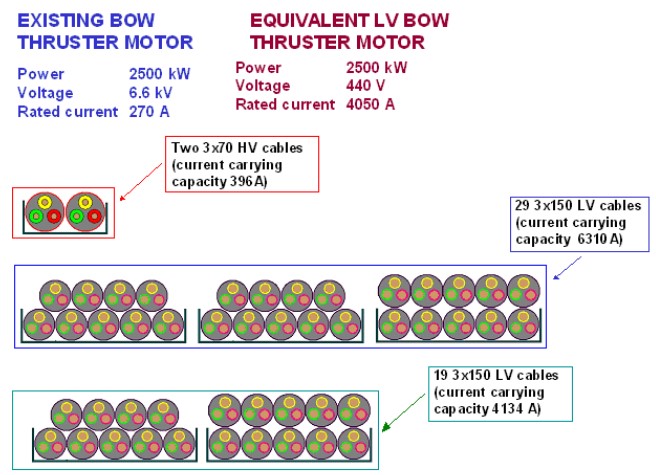
Volume of cables is significantly reduced in high voltage systems. As an example of cable size reduction possibilities, a comparison is made considering the bow thruster of a 138 000 m3 LNGC. The following are the characteristics of the existing bow thruster:
- Power – 2 500 kW.
- Voltage – 6,6 kV.
- Rated current – 270 A.
- Cables – 2 × 3 × 70 mm2 (current carrying capacity of each cable being 198 A, combined current caring capacity of the two cables in parallel is 396 A).
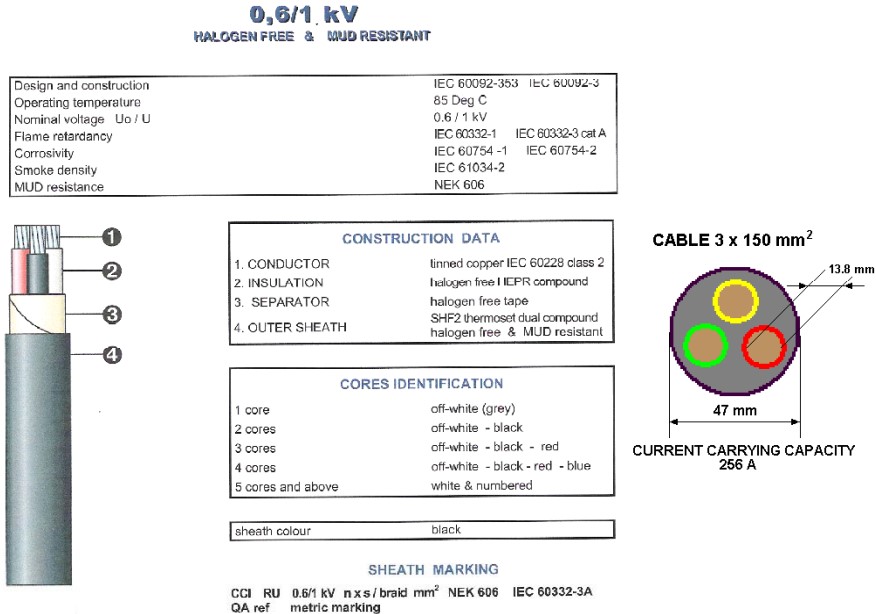
If it were feasible to use a low voltage bow thruster motor, the characteristics would be as follows:
- Power – 2 500 kW.
- Voltage 440 V.
- Rated current 4 050 A.
Assuming the use 3 × 150 mm2 LV cables having a current carrying capacity of 256 A each, 19 cables in parallel are necessary to feed the bow thruster motor (19 × 256 × 0,85 = 4 134 A (0,85 is the reduction factor to be applied when more than six cables are bunched). It is however to be noted that 19 cables are just enough to feed the bow thruster electric motor, while the proposed cables have a total carrying capacity in excess of the strictly necessary one. In order to have an equivalent current carrying capacity of the two HV cables (396 A at 6,6 kV corresponding to 5 940 A at 440 V), there would be the necessity of 29 LV cables.
The total section of copper necessary is 420 mm2 using HV cables and 8 550 mm2 using LV cables (however the actual copper section of LV cables equivalent to that of the two high voltage cable should be 13 050 mm2).
The gross section occupied by two high voltage cables should be around 67 cm2, while the gross surface occupied by 19 LV cables would be around 420 cm2 (640 cm2 if 29 cables are considered).
Considering that the specific weight of copper is 8,93 kg/dm3, assuming a length of cables of about 300 m, the total weight of copper with the HV cables would be about 1 125 kg, the total weight of copper using LV cables would be around 22 900 kg (about 35 000 kg if 29 cables are considered).
Figures 1, 2 and 3 give a visual idea of the above differences.
Additional Featurs
Certain disadvantages of high voltage systems exist with respect of low voltage systems, which are the necessity of the following additional equipment:
- high-voltage switchboard;
- step-down transformers (two sets) for AC 440 V ship service system (of course, no set-up transformer is required for the bow thruster).
Space
As a consequence of what indicated above, High Voltage Systems and Safe Electrical Equipmentthe high voltage systems have also the disadvantage of requiring more space for:
- Dedicated Space (Disadvantage) with warning plate to accommodate.
- HV Switchboard and Step-down Transformers (two sets) for AC 440 V Ship Service Systems.
Additional Advantages and Disadvantages of HV Systems Versus LV Systems
1) ADVANTAGES:
- Less Maintenance is required for HV Switchgear & Controlgear.
- No Periodical Replacement of circuit breakers is envisaged, hopefully for whole life of vessels, Circuit breakers in LV system need to be replaced for approx. 10 years interval (manufacturer’s general recommendation).
- Safety is increased due to higher grade of counter-measurements for protection against electrical shock hazard rather than LV switchgear and controgears.
2) DISADVANTAGES:
- HV switchgears (Metal Clad Type) and generators are more expensive.
- At least 2 step-down HV transformers are needed to feed 440 V systems.
- Dedicated space to house HV switchboard, HV feeder panel, HV transformers, etc. is to be provided.
- Dedicated cable routing and cable terminations are to be provided.
- Shielding of electro-magnetic field for HV equipment, if necessary, for Crew’s Health Safety is to be provided.
- HV-trained crew is necessary.
Safety Features in High Voltage Systems
Rotating Machines
HV rotating machines should have at least the following degree of enclosure:
- machinery casing – IP 23;
- terminal box – IP 44;
- motors accessible to not qualified personnel – IP 43.
A visual and audible alarm for high temperature in each phase stator winding is to be provided in control room.
Means to detect internal short circuits of generators are to be provided:
- to trip the generator breaker;
- to de-excite the generator (Exciting circuit to be short-circuited).
A visual and audible alarm should be activated in control room in such event. Generator stator windings are to have all phase ends brought out for the installation of the differential protection Double tube, water-cooled air circulation coolers are to be fitted with a visual and audible alarm for water leakage in control room.
Effective means (space heaters) are to be provided to prevent the accumulation of moisture and condensation within the machines when they are idle.
Table 1 summarizes the differences of the safety measures of HV and LV generators.
| Table 1. Comparison between HV and LV generators | ||
|---|---|---|
| ITEM | 440 V GENERATOR | 6,6 kV GENERATOR |
| IP PROTECTION FOR MACHINERY SPACE | IP 22 | IP 23 (Terminal box IP 44) |
| OVERCURRENT PROTECTION | Required | Required |
| UNDER-VOLTAGE PROTECTION | Required | Required |
| REVERSE-POWER PROTECTION | Required | Required |
| STATOR WINDING TEMPERATURE DETECTOR | Not required | Required |
| INTERNAL SHORT CIRCUIT DETECTION | Not required | Required |
| DIFFERENTIAL CURRENT PROTECTION | Not required | Required |
Switchgears and Control-Gear Assembly
Switchgears and control-gear assemblies should have at least IP 32 protection, IP 4X, if installed in spaces accessible to not qualified personnel.
Mechanical locking facilities are to be provided for withdrawable breakers, and switches in both service and disconnected positions.
Live contacts of the bus bars are to be covered by the fixed contacts of withdrawable breakers and switches in the withdrawn position.
Adequate number earthing and short circuiting facilities are to be provided for maintenance purposes.
Table 2 summarizes the differences of the safety measures of HV and LV switchboards.
| Table 2. Comparison between HV and LV switchboards | ||
|---|---|---|
| ITEM | LOW VOLTAGE SWITCHBOARD | HIGH VOLTAGE SWITCHBOARD |
| IP DEGREE FOR CONTROL ROOM | IP 22 | IP 32 |
| CIRCUIT BREAKERS OR DISCONNECTING SWITCH | Plug-in type is allowed | Withdrawable |
| MECHANICAL LOCKING FACILITY | Not required | Required |
| SHUTTER FOR CIRCUIT BREAKER | Not required | Required |
| EARTHING AND SHORT CIRCUITING FACILITY | Not required | Required |
| EARTH FAULT DETECTION | Not required | Required |
Additional recommendations not included in the Rules are the followings:
1) PROTECTION FROM ELECTRICAL SHOCK HAZARD
- Automatic disconnection of power supply feeder breaker (upper stream side) upon opening of a panel in HV switchboard, should be provided.
- Fixed insulation mat should be installed at both front and rear sides of each HV control-gear and each HV transformer.
2) FIRE SAFETY
Partition board between each generator panel and each feeder panel should be installed for separation of each panel.
Power Transformers
Power transformers should have at least IP 23 protection, IP 4X, if installed in spaces accessible to not qualified personnel.
Primary side circuit breaker or secondary side breaker (if fitted) should have coordinated tripping with breaker at feeder circuit in LV switchboard.
Automatic load shedding arrangement (preferential tripping) arrangement is to be provided where HV transformer supplies to LV switchboard.
Provision for protection (e. g. surge absorber at HV side) of transformer from voltage transients due to HF current interruption and current suppression is to obtained by:
- swiching;
- circuit breaker operation;
- or thyrister-switching.
Means are to be provided for detection (e. g. differential current relay) of phase-to-phase internal fault and activate alarm at control station or disconnect the transformer from HV system.
Means are to be provided for detection of earth fault for Y-neutral earthed transformer and activate alarm at control station or disconnect the transformer from HV system.
Over voltage protection is to be provided where LV system is supplied by HV system through transformer.
Table 3 summarizes the differences of the safety measures of HV and LV switchboards.
| Table 3. Comparison between HV and LV transformer | ||
|---|---|---|
| ITEM | 440/220 V TRANSFORMER | 6600/440 V TRANSFORMER |
| OVERCURRENT PROTECTION | Required | Required |
| COORDINATE TRIPPING | Not required | Required |
| LOAD SHEDDING ARRANGEMENT | Not required | Required |
| PROTECTION FROM ELECTRICAL DISTURBANCE | Not required | Required |
| PHASE-PHASE INTERNAL FAULT DETECTION | Not required | Required |
| OVER-VOLTAGE PROTECTION | Not required | Required |
| SPACE HEATER | Not required | Required |
| V–V CONNECTION AT SINGLE PHASE FAILURE | Allowable | Not allowable |
| ALARM/TRIPPING FEATURE FOR OIL IMMERGED TYPE | Not required | Required |
HV Cable Installation
HV cables cannot run in accommodation spaces. HV cables are to be segregated from cables operating at different voltage ratings. That means that HV cables cannot be installed on the same cable tray for LV cables. HV cables are to be properly marked for identification.
HV cables provided with continuous metallic sheath or armor with effectively bonding to earth may be installed on cable trays or equivalent. Cables with non-metallic Sheath/Armor are to be installed in metallic ducting or pipe for their entire length.
Cable termination are to be fitted with effective cover with suitable Response of Insulation Materials to Heatinsulating material.
Substantial barriers of suitable insulating materials for separation of phases from earth and each phase is to be provided at terminal box.
Precaution for relieving electrical stresses at termination points should be provided.
Additional Miccellaneous Recommendations
A warning plate “DANGER HIGH VOLTAGE” should be posted at all HV equipment and compartments.
Requirements of HV operating license for crew onboard by Union or the Flag Administration should be investigated.

- The Society of International Gas Tanker and Terminal Operators (SIGTTO). Liquefied Gas Handling Principles on Ships and in Terminals (LGHP4) / 4th Edition: 2021.
- The international group of liquefied natural gas importers (GIIGNL). LNG custody transfer handbook / 6th Edition: 2020-2021.
- American Gas Association, Gas Supply Review, 5 (February 1977).
- ©Witherby Publishing Group Ltd. LNG Shipping Knowledge / 3rd Edition: 2008-2020.
- CBS Publishers & Distributors Pvt Ltd. Design of LPG and LNG Jetties with Navigation and Risk Analysis / 4th Edition.
- NATURAL GAS PROCESSING & ITS ENERGY TRANSITION ROLE: LNG, CNG, LPG & NGL Paperback – Large Print, November 14, 2023.
- American Gas Association, Gas Supply Review, 5 (February 1977).
- The Society of International Gas Tanker and Terminal Operators (SIGTTO). Ship/Shore Interface / 1st Edition, 2018.
- Department of Transportation, US Coast Guard, Liquefied Natural Gas, Views and Practices Policy and Safety, p. IV-3.
- Department of Transportation, US Coast Guard, Liquefied Natural Gas, Views and Practices Policy and Safety, p. IV-4.
- Federal Power commission, Trunkline LNG Company et al., Opinion No. 796-A, Docket No s. CP74-138-140 (Washington, D. C.: Federal Power Commission, June 30, 1977).
- Federal Power Commission, Final Environmental Impact Statement Calcasieu LNG Project Trunkline LNG Company Docket No. CP74-138 et al., (Washington, D. C.: Federal Power Commission, September 1976).
- Federal Power Commission, «FPC Judge Approves Importation of Indonesia LNG».
- OCIMF, ICS, SIGTTO & CDI. Ship to Ship Transfer Guide for Petroleum, Chemicals and Liquefied Gases / 1st Edition, 2013.
- Federal Power Commission, «Table of LNG imports and exports for 1976», News Release, June 3, 1977, and Federal Energy Administration, Monthly Energy Review, March 1977.
- Office of Technology Assessment LNG panel meeting, Washington, D. C., June 23, 1977.
- Socio-Economic Systems, Inc., Environmental Impact Report for the Proposed Oxnard LNG Facilities, Safety, Appendix B (Los Angeles, Ca.: Socio-Economic Systems, 1976).
- «LNG Scorecard», Pipeline and Gas Journal 203 (June 1976): 20.
- Dean Hale, «Cold Winter Spurs LNG Activity»: 30.