LNG Plant Power System: Reasons for Choosing High Voltage solutions include the ability to reduce energy losses and increase the overall efficiency of the power distribution system. High voltage systems also enable the use of smaller conductors, which can result in significant cost savings and reduced material requirements.
The use of high voltage in LNG plant power systems also provides greater flexibility and scalability, allowing for easier integration of new equipment and expansion of the facility as needed. Additionally, high voltage systems can improve the reliability and availability of the power supply, which is critical for ensuring the safe and continuous operation of LNG processing and production facilities.
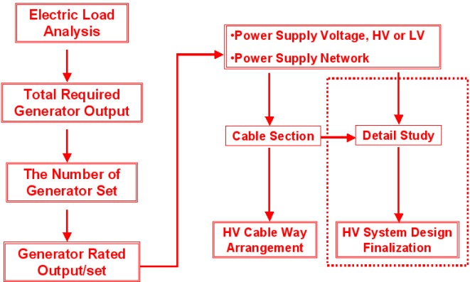
Planning Flow of Power Supply System
A High Voltage Electrical system is defined as a system having nominal voltage (phase to phase) exceeding 1 kV, but not to exceed 15 kV.
«Note: Onshore electrical classifications would consider this as “Medium Voltage”.»
The selection of Ship Electrical Systema high voltage system for ship service depends from several factors and is in particular dictated by the required generator outputs.
In general:
- Low voltage system is suitable when the nominal output of each generator is below 8 000 kW;
- High voltage system is suitable when the nominal output of each generator is over 10 000 kW;
- Both systems are suitable when the nominal output of each generator is between 8 000 and 1 000 kW.
The following flow chart (See Figure 1) represents the flow of consideration to be done for the selection of the most appropriate system for a certain application.

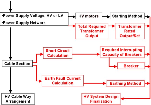
Once the system High Voltage has been selected, a detailed study of the plant is carried out in accordance with the following flow chart (See Figure 2).

Reasons for Selecting High Voltage System
In general, a high voltage system is to be chosen when the power demand is such as to exceed the lower voltage limitations. These limitations are as follows:
- Interrupting capacity limits of breakers for short circuit current.
- Production limits of rotating machines.
- Capacity limits of control devices.
- Earthing method of generator neutral points.
- Volume of installed cables.
Interrupting Capacity of Circuit Breakers
The following Table 1 indicates the limitations of the circuit breakers.
| Table 1. Maximum Capacity of Low Voltage Circuit Breakers | |||
|---|---|---|---|
| RATED CURRENT | INTERRUPTING CAPACITY (BREAKING/MAKING) | POWER SUPPLY CONDITIONS | |
| ACB | 6,3 kA (ABS type approved) | 85/206 kA 133/330 kA | Total generator capacity (3-4 sets) 13 200-17 000 kVA or Single generator capacity 4 400 kVa |
| MMCB | 2 kA (ABS type approved) | 85/195 kA 75/188 kA | |
| 4 kA | 85 kA (breaking capacity) | ||
Table 2 shows the characteristics of some standard high voltage switchboard approved in Japan.
| Table 2. Standard HV Switchboards | |||
|---|---|---|---|
| MAKER | MAIN BUS BAR CAPACITY (MAX) | RATED WITHSTANDING CAPACITY | |
| GENERATOR PANEL | JRCS | 3 000 A | 25 kA |
| TAIYO ELEC | 1 900 A | 25 kA | |
| TERASAKI ELEC | 2 000 A | 25 kA | |
| UZUSHIO | 1 250 A | 20 kA | |
| MAKER | RATING OF CIRCUIT PROTECTION DEVICE | MAX. CAPACITY OF POWER SUPPLY | |
| FEEDER PANEL AND STARTER PANEL | JRCS | 600 A or 1 200 A | 6 000 kW or 12 000 kW |
| TAIYO ELEC | 630 A | 5 000 kW | |
| TERASAKI ELEC | 200 or 400 A | 1 500 kW or 3 000 kW | |
| UZUSHIO | 600 A | 6 000 kW | |
Production Limits of Rotating Machines
In general, the power production limits of rotating machines vary between 2 500 and 4 000 kVA for generators and between 1 000 and 1 200 kW Boat Outboard Motorsfor motors.
High voltage machines are to be used in case production limits for rated output of LV generator or LV motor are exceeded.
High Voltage machines have the additional advantage of:
- being less expensive than low voltage machines;
- being more space efficient than low voltage machines.
Magnetic Contactor Capacity Limits
The magnetic contactor capacity limit is around 1 600 A.
Earthing Methods for Generator Neutral
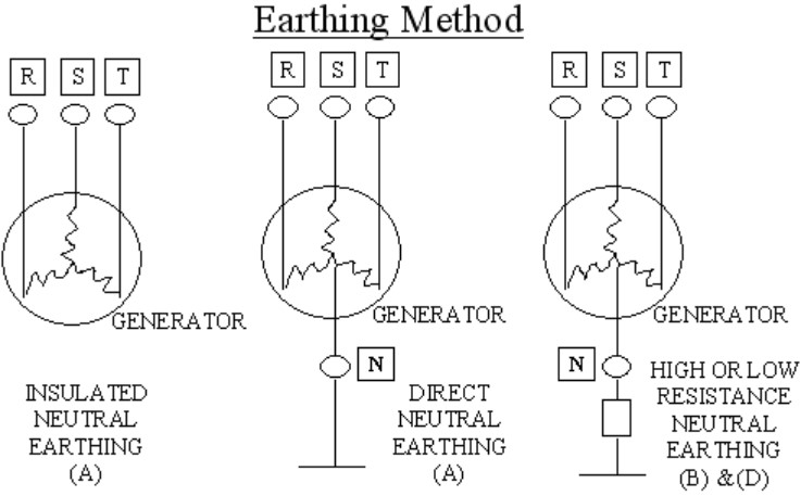
In general low voltage systems have insulated neutral. For high voltage systems there are four methods to earth generator neutral:
- insulated neutral earthing (neutral is NOT earthed), this being the most used system in Europe and Japan;
- high resistance neutral earthing, this system also being commonly used in Europe and Japan;
- direct neutral earthing;
- low resistance neutral earthing, this being the most used system in USA.
The following sketch (See Figure 3) shows the above methods.

According with IACS UR E11 (2001) and with IEC 60071, the definition of high or low resistance neutral earthing is based on the value of the earthing factor as follows:
- High Resistance Neutral Earthing: Earthing Factor is higher than 0,8.
- Low Resistance Neutral Earthing: Earthing Factor is lower than 0,8.
Earthing factor is defined as the ratio between the phase to earth voltage of the healthy phase and the phase to phase voltage. This factor may vary between 1/√3 and 1.
The decision on the neutral method application is to taken taking into account the advantages and the disadvantages of the various methods.
1) INSULATED NEUTRAL EARTHING SYSTEMS
In case of single line (one phase) earth fault, earth fault current is:
- very small;
- derived from electric capacitance between the fault generator and hull.
This assures continuity of the power supply and can be considered an advantage of this method.
Due to increase of voltage to earth of the remaining healthy phase, it needs a sufficient dielectric endurance capability. This is a disadvantage of this system.
Due to the very small earth fault current, earth fault detection is difficult. This is a disadvantage of this system.
2) HIGH RESISTANCE NEUTRAL EARTHING SYSTEM
Transient excessive over-voltage upon occurrence of single line earth fault is reduced, this not being achieved by the insulated neutral earthing method. This assures the continuity of the power supply and can be considered an advantage of this method.
Dielectric endurance capability can be reduced rather than insulated neutral earthing method. This is another advantage of this system.
3) DIRECT NEUTRAL EARTHING METHOD
Due to capability of disconnecting the earth fault circuit by large earth fault current upon occurrence of single line earth fault, continuity of power supply is not obtainable. This is a disadvantage of this system.
Due to possibility to avoid increase of the voltage to earth of the remaining healthy phase, dielectrical endurance capability is reduced. This is an advantage of this system.
Due to the large earth fault current, detection of each fault current is easy. This is another advantage of this system.
Generators running in parallel with unbalanced load current create excessive current from generator neutral to earth. Harmonic distortion will occur in generated voltage wave, i. e. the 3rd harmonic distortion. Due to this harmonic distortion in generated voltage wave, overheating of generator windings may happen. Accordingly, generator windings need to have a capability for withstanding this overheating. This is another disadvantage of this system.
4) LOW RESISTANCE NEUTRAL EARTHING SYSTEM
The fault circuit disconnects by detection of earth fault current and protection for the fault generator against overheating by selection of resistance for neutral earthing improves. This makes easy fault detection and is an advantage of this system.
Table 4 summarizes the advantages and the disadvantages of the various earthing methods.
| Table 4. Comparison of Earthing Systems | ||||
|---|---|---|---|---|
| INSULATING NEUTRAL EARTHING | HIGH RESISTANCE NEUTRAL EARTHING | DIRECT NEUTRAL EARTHING | LOW RESISTANCE NEUTRAL EARTHING | |
| CONTINUITY OF POWER SUPPLY | O | O | Δ | X |
| DIELECTRIC ENDURANCE CAPABILITY | X | O | O | O |
| EARTH FAULT DETECTION | X | Δ | O | O |
| GENERATOR PARALLEL RUNNING | O | O | X | O |
| O Advantage X Disadvantage Δ Case by case | ||||
Volume of Cables
Selection of a high voltage over a low voltage system directly affects:
- price of electric equipment and cables;
- work load of cable installations;
- space for cable installations (cable ways);
- selection of cable tray and conduit systems available.

