The cargo storage system in liquefied natural gas (LNG) carriers, commonly referred to as LNG tanks, encompasses various designs and technologies aimed at safely containing and transporting LNG in its cryogenic liquid form. These tanks are typically constructed using specialized materials such as high-grade steel or advanced alloys to withstand extreme temperatures and pressures. LNG tanks can be classified into different types, including membrane tanks, spherical tanks, and prismatic tanks, each offering unique advantages in terms of capacity, structural integrity, and thermal insulation. Membrane tanks, for instance, consist of a primary membrane surrounded by insulation layers and a secondary barrier, providing flexibility and excellent thermal performance. Spherical tanks, on the other hand, offer robust structural integrity and are suitable for larger LNG carriers, while prismatic tanks are often used in smaller vessels or as part of hybrid cargo containment systems. Overall, the design and selection of LNG tanks play a crucial role in ensuring the safe and efficient transportation of LNG aboard LNG carriers, meeting stringent regulatory requirements and industry standards.
- Existing LNG Carriers Cargo Containment System Concepts
- Ships with Internal Insulation Tanks
- Ships with type “A” Independent Cargo Tanks
- Type “C” Independent Tanks
- Today’s Cargo Containment System
- Membrane Tanks Concept
- Independent Spherical Tank Concept
- Comparison of Cargo Containment System
- Membrane Tank Vessels
- Spherical Tank Vessels
- Independent Prismatic Tank Vessels
In comparison, spherical and prismatic tanks are alternative cargo containment systems used in LNG carriers. Spherical tanks are typically constructed of high – grade steel and offer robust structural integrity, making them suitable for larger LNG carriers. Prismatic tanks, on the other hand, are rectangular – shaped and can be constructed using either membrane or metallic materials. They are often employed in smaller LNG carriers or as part of a hybrid cargo containment system. When comparing cargo containment systems, factors such as cost, weight, capacity, and safety considerations must be carefully evaluated to determine the most suitable option for a given LNGC project. Each system has its own advantages and limitations, and the selection depends on the specific requirements and constraints of the project, as well as regulatory compliance and industry standards. Overall, the cargo containment system plays a crucial role in ensuring the safe and efficient transportation of LNG aboard LNG carriers.
Existing LNG Carriers Cargo Containment System Concepts
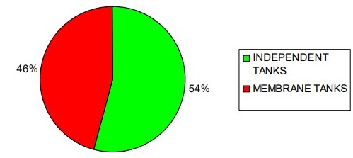
While several different types of containment systems, complying with the requirements of the IGC Code, have been proposed, most of the LNG vessels built up to now can be divided into two categories: membrane tanks, and independent free type B standing tanks. In fact, other systems, used for the first tentative LNG ships were abandoned. Figure 1 shows that a little more than one half of the existing LNGC fleet carries cargo in independent cargo tanks, while a little less than one half of the fleet carries LNG on membrane tanks. The figures in this diagram are likely to change substantially in the next years, as the majority of the new orders and new options are for membrane type ships.
Ships with Internal Insulation Tanks
A first tentative to transport Overview of the Carriage of Liquefied Gases by SeaLNG by sea was done with the barge “METHANE” built in 1952 with balsa wood lined tanks. It was an example of the theoretical ideal liquefied gas containment made completely of insulating material. Another example of this approach was the “PIONEER LOUISE” an LPG carrier utilizing internally insulated tanks, i. e., the cargo was in contact with the insulation made of sprayed polyurethane. Insulating materials have low thermal conductivity in comparison with metals. Heat flow in an insulating material is several times less than steel, aluminum, etc., while the thermal conductivity of gases is about ten thousand times lower than metals.
The LPG carrier “PIONEER LOUISE” had double hull in order to make the insulation supporting surface completely flush so the polyurethane foam could be sprayed directly to the interior surface free of any structural members. Polyurethane foam is a rigid closed – cell structure that is a mass of bubbles. A foam barrier containment system assumes that some quantity of liquid would penetrate the insulation surface, however, the penetrations are minimized by evaporation of the liquid, which forms a vapor barrier and impedes further liquid penetration.
Unfortunately, the concept of using insulation to line ordinary steel load bearing tanks was a failure. The surface penetration of balsa wood by the LNG and the resulting evaporation from the surface cells when, the liquid level was changing, damaged the cells containing the liquid. The synthetic materials enjoyed no better fate. The sprayed polyurethane, used even as a secondary barrier, fractured during the first cooling down. As a result of these failures, the idea of containment systems using insulating materials in contact with the cargo was abandoned, even though this system is allowed in principle by the IGC Code.
Ships with type “A” Independent Cargo Tanks
Three systems of cargo containment systems with type “A” independent cargo tanks were developed in the late sixties-early seventies:
a) CONCH
This system, used for the first LNGC that crossed experimentally the Atlantic Ocean on 1959 the “METHANE PIONEER“. After the success of this voyage other two ships of this type were built:
- the “METHANE PRINCESS“;
- the “METHANE PROGRESS“.
These two ships of 27 400 m3 capacity were built on 1964 and scrapped on 1997 and 1986 after 33 and 22 years of trouble – free service. The CONCH system consisted of prismatic aluminum tanks with secondary barrier of plywood/balsa.
b) GAS DE FRANCE
The cargo containment service consisted of stainless steel cylinders with insulation and secondary barrier combined. The ship “CINDERELLA” of 25 500 m3 capacity built on 1965 with this system is still in service.
c) ESSO DESIGN
The cargo containment system consisted of prismatic aluminum primary and secondary tanks. Over the three 41 000 m3 capacity ships built in Italy between 1968 and 1969 two are still in service. A fourth ship of this design built in Spain is also still in service.
As it can be noted by the fact that all these ships, built on the late sixties, are still in service or have been scrapped only a few years ago, all these designs were quite successful. However, the type “A” tank concept has been abandoned. The reason is the fact that the type “A” independent tanks require a complete secondary barrier, which means a complete expensive double tank, while only a partial secondary barrier is allowed for the type “B” independent tanks. Moreover, the modern numeric analysis techniques made more and more possible the performance of reliable fatigue and crack propagation analysis that allow the elimination of the complete secondary barrier, making the ships a little smaller and less expensive.
Type “C” Independent Tanks
Even though this kind of tanks is, in principle, suitable for LNG carriers and acceptable in accordance with the IGC Code and the Rules, no LNGC ships have been ever built with this system. The reason is that tanks “C” are pressure vessels for the transportation of pressurized liquid gases. In order to keep their scantling within reasonable limits they must have volumes limited to few thousands of cubic meters. These volumes are so far away from the LNG volumes to be transported by even the smallest LNG ships to make this system not suitable for LNG.
Today’s Cargo Containment System
As already mentioned the systems used for the today’s LNGC ships are two: membrane tanks and type “B” independent freestanding cargo tanks. Each of these two categories may be further divided into two categories as follows:
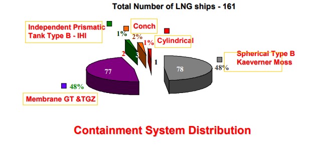
- Membrane tanks adopting “Gaz Transport” technology and membrane tanks adopting “Technigaz” technology. It is interesting to note that these two companies have merged some years ago and now they have developed a combined system named CS1. Presently only three ships, which construction just started in France, have adopted this new concept. All membrane type ships have been built according with one of the two above concepts. Of the existing fleet of membrane type ships about 68 % adopted the GT technology and about 32 % percent TZ technology. Presently other engineering companies are studying new membrane concepts with the intent to breaking GTT’s monopoly in this field.
- Spherical tanks and prismatic tanks. The ships built with type “B” prismatic tanks are only two. This makes their percentage with respect of all the independent tank ships a little more than 2 %. It seems difficult that this project will be successful in the near future, due to its high cost, specially considering that most of the shipyards the build LNGC ships have already acquired experience and equipment suitable for the other more popular systems.
Figure 2 indicates the actual share of cargo containment system in the present fleet.
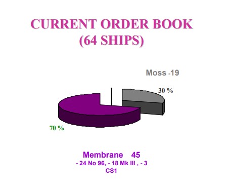
As already stated for Figure 1, there is presently a tendency of increase of the membrane type ships and in particular of those adopting the TZ concept design MARK III. This tendency is clearly evident in Figure 3.
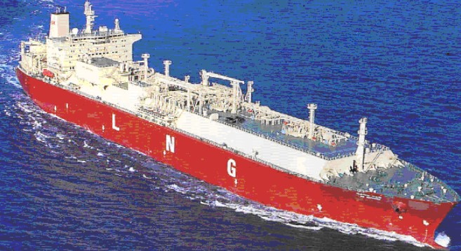
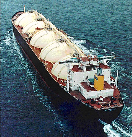
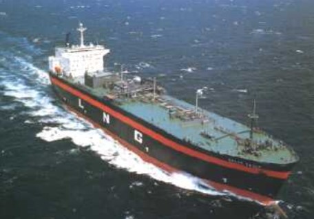
Figures 4, 5 and 6 show photographs of a membrane ship, a Moss-Rosenberg ship and SBM (type “B” independent tank) ship.
Membrane Tanks Concept
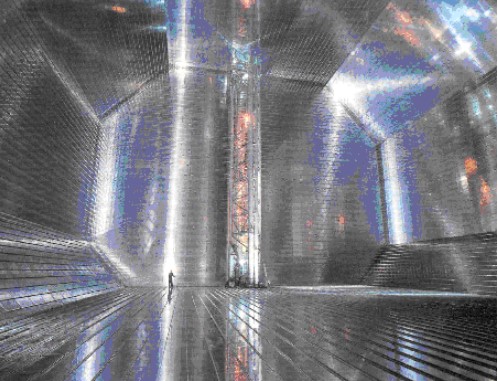
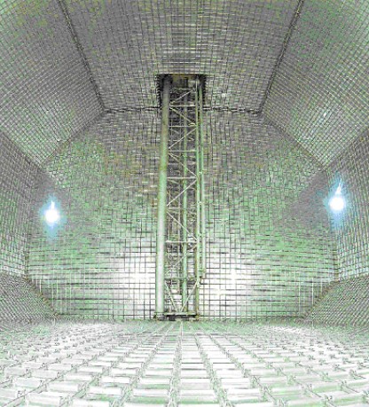
Basically this system is made of a thin membrane of stainless steel or high nickel alloy, called “INVAR” (from the word invariable), which is in contact with the cargo and forms the primary barrier. A complete secondary barrier is required and this barrier may be constituted by the same material as the primary barrier or by other non-metallic suitable material. In general the membrane Cargo System – Tank Constructiontanks vessels built up to now adopt either the Gaz Transport or the Technigaz concept. Figures 7 and 8 show the interior of a tank of a GT ship and of a TZ ship.
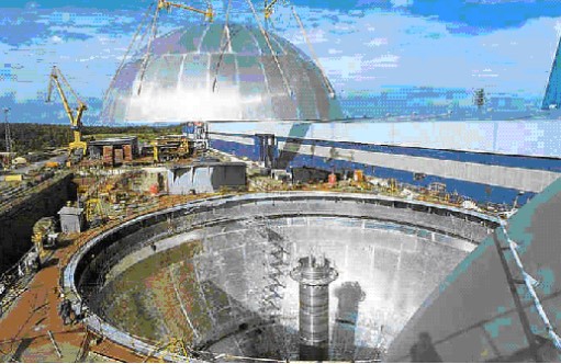
Independent Spherical Tank Concept
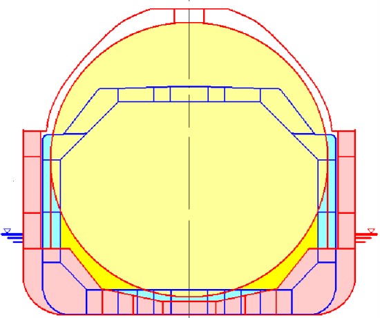
Cargo containment system of gas vesselThe cargo containment system is made of an unstiffened spherical tank supported at the equator by a vertical cylindrical skirt. The bottom of the cylindrical skirt is welded integrally into the ship hull structure. The skirt is attached to the equator of the sphere by welding a specially shaped section. Figure 9 shows a typical section of a spherical tank.
Comparison of Cargo Containment System
Considering the two membrane systems (Gaz Transport and Technigaz) equivalent for the scope of the following comparison (a comparison between the two systems will be discussed under Module 8), we shall consider the advantages of each of the following systems:
- Membrane type.
- Spherical independent tank type.
- Prismatic independent tank type.
It might be interesting to note that some of these advantages might be considered as a disadvantage from another point of view, such as for instance the existence of a complete secondary barrier.
Membrane Tank Vessels
The main advantages of the membrane tank vessels are:
a) SMALLER SHIP PRINCIPAL DIMENSIONS
The ships with membrane containment system make a more efficient use of the cargo hold volume than those with containment system based on independent cargo tanks, where a certain space is to be left between the inner hull and the tanks. Of course a smaller ship is in general less expensive to build. Figure 10 shows a comparison between the midship sections of a membrane type LNGC of 138 000 m3 capacity and a 135 000 m3 Moss-Rosenberg type LNGC. The figure gives a clear idea of the difference of dimensions.
b) SMALLER DISPLACEMENT
As a consequence of the reduced dimensions.
c) LOWER POWER REQUIREMENTS
As a consequence of the reduced dimensions.
d) LOWER FUEL CONSUMPTION
As a consequence of the reduced dimensions.
e) LOWER GROSS TONNAGE
As a consequence of the reduced dimensions.
f) LOWER WINDAGE AREA
As a consequence of the reduced dimensions.
g) BETTER VISIBILITY FROM WEELHOUSE
The deck structure is quite “clean” without obstacles to the visibility, like the spheres.
h) NO SHIPYARD INVESTMENTS REQUIRED
The construction of the independent tanks requires investments from the shipyards that have to provide specialized production lines for the tanks.
i) LESS SOPHISTICATED CALCULATIONS REQUIRED
There is no necessity of sophisticated analyses of the cargo tanks.
j) PRESENCE OF A COMPLETE SECONDARY BARRIER
It can be considered an advantage from the overall safety point of view and a disadvantage from the construction cost point of view.
k) BETTER SUITABILITY FOR INCREASING DIMENSIONS AND CARGO CARRYING CAPACITY
Cargo carrying capacity may be increased just increasing the dimensions of the tank keeping the same geometry and ship structural design.
Spherical Tank Vessels
The main advantages of the spherical tank vessels are:
a) LESS QUANTITY OF INSULATION MATERIAL
The surface area of the spherical tank is much less than that of the membrane or prismatic independent tank having the same capacity. Therefore the quantity and the weight of the insulation material is less.
b) INCREASED SAFETY UNDER COLLISION AND GROUNDING
The spherical tank is exposed only at one point at each side (the equator) and one point at bottom at the minimum inboard distance prescribed by the IGC. Hence the majority of the tank is at a bigger distance from the side shell than in the other configurations. This increases safety in case of collision or grounding.
c) FASTER CONSTRUCTION
The tanks may be built in parallel with the ship, while the installation of the membrane cannot start until the construction of the holds has been completed.
d) IMPROVED QUALITY CONTROL
The tanks are built in workshop with controlled ambient condition where it is possible to apply an effective quality control system.
e) LESS FREE SURFACE EFFECTS
Due to the shape of the tank the free surfaces of liquid are less than in the prismatic tanks.
f) BETTER SLACK LOADING
In general these tanks can be loaded at any level without sloshing damages can occur.
g) BETTER FILLING RATIO
Due to the shape of the tank it is possible to load the cargo at an increased filling ratio.
h) BETTER OFF-LOADING POSSIBILITIES IN CASE OF FAILURE OF PUMPING
SYSTEM
Due to the fact that the tanks are actually pressure vessels, it is possible to discharge the cargo by gas pressure in case of loss of the pumping system.
i) POSSIBILITY TO USE A PARTIAL SECONDARY BARRIER
It can be considered a disadvantage from the construction cost point of view and an advantage from the overall safety point of view.
Independent Prismatic Tank Vessels
The main advantages of the independent prismatic tank vessels are:
a) SMALLER SHIP PRINCIPAL DIMENSIONS
The prismatic self-supporting tank containment system makes a more efficient use of the cargo hold volume than the spherical tank system, however the dimensions are greater than the membrane vessels.
b) SMALLER DISPLACEMENT
This is an advantage only compared with the sphere tank vessel, is a disadvantage compared with the membrane vessel.
c) LOWER POWER REQUIREMENTS
This is an advantage only compared with the sphere tank vessel, is a disadvantage compared with the membrane vessel.
d) LOWER FUEL CONSUMPTION
This is an advantage only compared with the sphere tank vessel, is a disadvantage compared with the membrane vessel.
e) LOWER GROSS TONNAGE
This is an advantage only compared with the sphere tank vessel, is a disadvantage compared with the membrane vessel.
f) LOWER WINDAGE AREA
Same as per membrane vessels.
g) BETTER VISIBILITY FROM WEELHOUSE
Same as per membrane vessels.
h) INCREASED SAFETY UNDER COLLISION AND GROUNDING
The prismatic independent tanks are at a greater distance than the membrane tanks from the shell side. However they are much closer than in the spherical tank vessels.
i) FASTER CONSTRUCTION
Same as per spherical tank vessels.
j) IMPROVED QUALITY CONTROL
Same as per spherical tank vessels.
k) LESS FREE SURFACE EFFECTS
Due to the presence of bulkheads inside the tanks the problem of free surface effects and sloshing are not as important as in membrane vessels.
l) BETTER SLACK LOADING
The presence of the longitudinal bulkhead and the transverse swash bulkhead facilitates the slack loading.
m) POSSIBILITY TO USE A PARTIAL SECONDARY BARRIER
Same as per spherical tank vessels.