Traditionally LNG carriers were operated by specialists with long experience with this type of vessel. As the LNG market expands there have been calls from some parts of the industry to reduce costs and shipping is one area that could be targeted. CAP program is created to check, if Liquefied Gas Carrier are follow a special requirements.
- Summary
- Nomenclature
- Introduction
- Background to the LNG Cap
- The Rating System
- The Hull
- VeriSTAR Hull
- 3D FEM Analysis
- Fatigue Analysis
- Timing
- Cargo Containment
- Moss
- Membrane
- Cargo Handling
- Safety Systems
- Propulsion
- Boilers
- Main Turbine
- Main Gearbox
- Main Condenser
- Feed System
- Auxiliary Equipment
- Electrical & Instrumentation
- Generation
- Distribution
- Instrumentation
- Ship Inspection
- Reporting
- Conclusions
Summary
There have also been moves by operators with no previous experience of LNG carriers, to buy up older ships and to charter them out. In this context, and in accordance with industry demands, Bureau Veritas has developed a comprehensive LNG Condition Assessment Program for older LNG carriers.
Nomenclature
- BV – Bureau Veritas;
- CAP – Condition Assessment Program;
- LNG – Liquefied Natural Gas.
Introduction
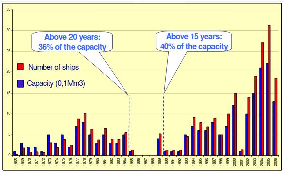
The LNG shipping industry compared with other sectors is quite small; in fact it has been called at times an exclusive club. There are at the time of writing about 165 LNG ships in service and about 76 vessels on the order book.
There is however a huge requirement for LNG carriers and therefore older ships are still in great demand as a large part of the LNG delivery chain. For instance about 36 % of the LNG delivery capacity is over 20 years old and 40 % is over 15 years old.
As pressure increases upon owners and managers to cut costs, as the supply of spare parts becomes difficult due to equipment being obsolete, combined with a distinct shortage of qualified personnel particularly steam engineers then there is the potential for serious failures of the LNG supply chain.
Background to the LNG Cap
Very specific requirements were laid down by those requiring the development of an in depth LNG Condition Assessment Program. These had to cover:
- the hull and hull integrity,
- the cargo containment systems,
- the cargo handling machinery,
- the main propulsion plant including the electrical installation, power generation and distribution.
It was necessary to develop the in depth instructions and criteria to be applied in order to be able to rate each part of each system and ultimately to issue a global rating for each area.
The Rating System
The purpose of a CAP is to provide a rating of each system examined against a set of standard criteria. In order to do this it was necessary to develop these standard criteria. There already existed a basic set of criteria in the BV Guidance Note 465, Harmonised Condition Assessment Program. These criteria (as listed below) were used as a basis to form those specialist criteria required for particular areas.
A Rating 1
Items and systems examined and function tested. Only superficial reductions as from as new or current rule requirements. Found with no deficiencies affecting safe operation and/or performance. Documentation and maintenance practices considered good. No maintenance or repairs required.
B Rating 2
Items and systems examined and function tested. Found with minor deficiencies not affecting the safe operation and/or normal performance, thicknesses significantly above class limits. Documentation and maintenance practices considered adequate. No immediate maintenance or repairs considered necessary.
C Rating 3
Items and systems examined and function tested. Found with deficiencies not affecting the safe operation and/or normal performance, thicknesses while generally above class renewal limits found with substantial corrosion. Documentation and maintenance practices considered to be of a minimum standard. Some maintenance and repairs may be considered necessary.
D Rating 4
Items and systems examined and function tested. Found with deficiencies significantly affecting the safe operation and/or normal performance, thickness’ at or below class renewal limits. Documentation and maintenance practices considered to be inadequate. Maintenance and repairs required to re-instate serviceability.
The Hull
The hull of an LNG carrier is not subject to the same stress and fatigue of say a tanker of similar size. This is due in part to the fact that the draught on an LNG carrier does not vary to the same extent between ballast and loaded as it does on a tanker.
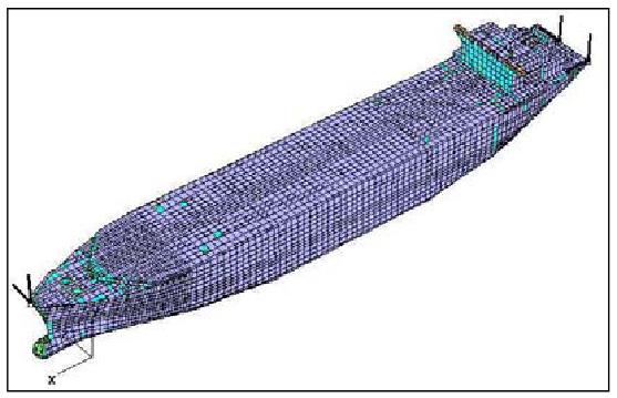
There are, however, a number of areas that require close examination in order to be assured of the structural integrity of these ships. To do this a finite element study is carried out to provide information on areas of higher stress and also the fatigue life. This gives information to the surveyor guiding him to areas of potential problems during the survey on board, and providing to the owner the anticipated remaining fatigue life of the hull.
VeriSTAR Hull
In Bureau Veritas the finite element analysis is carried out using the VeriSTAR Hull program, which provides a method for rapidly modelling the hull structure and in the first stage provides information on yielding and buckling compared directly to the rule requirements.
The VeriSTAR hull model is developed from a BV Mars section from which details of scantlings, longitudinals and stiffners are provided.
3D FEM Analysis
This is the first step in the LNG CAP process which allows us to focus the inspection on board in the most critical areas. An “as built” model is prepared as the starting point reference. This model is then updated with the latest thickness gaugings taken on board together with any modifications that have taken place during the vessels past life.
The model is built using coarse mesh and fine mesh where necessary and extends over the whole length of the vessel. The coarse mesh is used at the fore and aft ends and the cargo area is made with a finer mesh using two elements longitudinally between ajacent primary webs. The first model identifies potential areas where it will be necessary to further refine the mesh size.
All structural members are modelled according to their original shape using the following types of elements:
- Quadrilateral orthotropic Orthotropic shell elements are used because they take in-plane and out-of-plane deformations. These are elements commonly used in ship design. Moreover the orthotropic shell includes the secondary stiffners so that the buckling phenmomena can be checked everywhere on the hull automatically. This is not the case with standard elements. If necessary however other types of elements can be used for the modelling.x shell elements defined by four nodes each with six degrees of freedom including the secondary stiffners;
- Triangular plate elements defined by three nodes, six degrees of freedom per node;
- Beam elements defined by two nodes, six degrees of freedom.
A Loading Conditions
Several representative loading cases are studied, including bow down and stern down conditions.
An independent detailed analysis of the ships structural response to applied static and dynamic loads is undertaken. This first phase will allow determination of the critical areas of the structure to focus the detailed spectral fatigue analysis on the most critical items. The analysis is performed using Bureau Veritas requirements for LNG carriers in world wide trading.
Fatigue Analysis
By refining the FEM VeriSTAR hull model the fatigue life of those structural details with the shortest fatigue life (those that might fail within the ships proposed working life span) can be studied. The fatigue analysis is conducted in two parts:
- The standard deterministic BV fatigue rule calculation is performed in order to scan the most important details.
- A complementary spectral fatigue assessment is performed to obtain more accurate fatigue results in some specific hot spots. This phase is based upon a full hydrodynamic model coupled to the structural FEM model.
Two types of details are studied:
- Fatigue assessment of all longitudinal secondary member end connections within the cargo area.
- Fatigue assessment by “zoom in” fine mesh modelling for hot spot areas of the primary structure.
A Meshing Arrangements
For the fatigue analysis, the size of the mesh is generally of the same magnitude as the thickness of the plate As illustrated in Pic. 3 for the connection of the transverse bulkhead cofferdam to the inner bottom.
B Deterministic Spectral Fatigue Analysis
A full detailed deterministic and Fatigue Assessment of Typical Details of Very Large Gas Carriers (LPG)spectral fatigue analysis is carried out to verify that satisfactory long term structural performance can be achieved over the anticipated operational life of the vessel. For this purpose the following calculations are performed:
- Accumulated fatigue damage, based upon the past trading history.
- Expected fatigue life, based upon future trading information if available.
The wave data used will be those encountered on the specific trading routes. Any periods of inactivity such as lay up is taken into account as will any corrosion control measures used.
The results of the full spectral analysis are compared to the standard deterministic fatigue rule calculations.
The fatigue analysis is performed for some details already known to be suspect areas subject to fatigue, but generally fatigue damage and expected design life are computed for the following families of structural details:
- Connection details between longitudinals and primary members.
- Selected structural details of connections between primary members and transverse bulkheads, stringers and side brackets.
- Connection of horizontal wing ballast tank stringers to transverse cofferdam bulkheads.
- Connection of transverse bulkhead cofferdams to inner bottom.
- Connection of inner trunk deck of transverse bulkhead cofferdam.
- Bilge area sloping hopper plate knuckles upper and lower.
- Connection of trunk deck to upper deck.
- Area of trunk deck intersection with deck house.
- Connection of tank covers to main deck including brackets.
- Transition points where parallel body cargo tank boundaries are knuckled in way of forward and after hull form.
- End of partial girder with connections to ordinary stiffners.

Timing
The timing of the CAP process will be discussed in detail later. However, the most important factor to consider is the timing of the Hull structural analysis which will enable accurate information to be available before the time of hull inspection and in good time for the owner to prepare for any repairs or modifications.
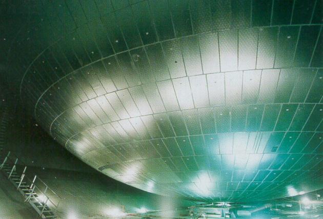
Cargo Containment
In reality the type of cargo containment can be split into two types:
- Moss;
- Membrane.
And both can be split into the various different types:
For Moss:
- 9 % Ni. steel;
- Aluminium bi-metallic skirt joint;
- Aluminium tri-metallic skirt joint.
For Membrane:
- Gaz Transport:
- NO-82.
- NO-85.
- NO-88.
- NO-96.
- Technigaz:
- MK I.
- MK II.
There are of course other containment systems that could be encountered such as the original 9 % Ni steel Gaz Transport system, IHI SPB free standing tanks but these would be covered as special cases as and when requested.
The condition assessment of the Cargo Containment Systems of LPG and LNGcargo containment system is based upon a thorough inspection of the covers, insulation, void spaces, cofferdams and the tank itself, be it membrane or moss, in addition the pump mast/pump tower is thoroughly inspected. Additionally any special requirements such as the membrane global test or examination and de-lamination testing of the bi-metallic skirt joints for the moss system, are also carried out/monitored and the results used as part of the rating system.
Different rating criteria were developed for the different containment systems and rather than reproduce them here a copy of the BV LNG Annex to Guidance note 486 is available upon request.
There are of course some well known areas that require examination and these will be discussed for each of the containment types.
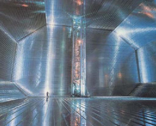
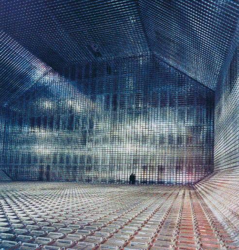
Moss
The Moss containment system is a very robust and heavy system that has evolved over the years. The first commercial types had 9 % Ni. Steel tanks, however only two ships were built like this before aluminium alloy became the standard material. Along with the introduction of aluminium came the requirement to join the upper part of the skirt as part of the equatorial ring, with the steel skirt. This was achieved first with a bimetallic joint see Pic. 4.
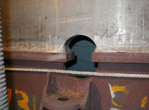
Unfortunately there has been a problem in some cases with de-lamination of this joint. In most cases where this has occurred the joint is under very strict scrutiny in order to monitor any progress or worsening of the delamination.
Although Moss tanks have an enviable reputation for trouble free service there have been occasions where cracks have been found. For CAP it is therefore necessary to ensure that there is no cracking of the moss containment and a program of ultrasonic scanning and other non-destructive testing of selected weld joints is carried out.
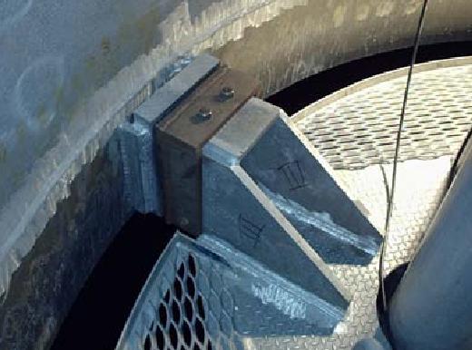
The location method of the pump tower has changed over the years as the change was made from steel to aluminium. In earlier designs the tower was free to move and had sliding shoes to take up the thermal expansion (see Pic. 5) in the latest designs the tower is fixed and any movement is handled by diaphragm plates or similar.
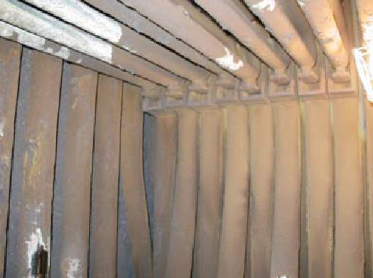
The insulation of a moss tank can be of two different kinds. Wound or panel. Of note with the wound system are the springs and stainless steel straps the hold up the lower part of the insulation covering the sphere. The insulation is examined to ensure that it is secure, undamaged, functional and free of ice.
On moss vessels there are large cargo holds or void spaces which give easy access to the internal hull structure. A thorough examination of these spaces will indicate any difficulties with the structure particularly cracking at the base of the longitudinal knuckles and ballast tanks (Pic. 6).
Membrane
The concept of the membrane containment systems is different to that of Moss. This has been discussed at length many times before and will not be entered into here. However the differences mean that the inspection and testing of membrane systems is very different to that of Moss.
A Global Test
The principal requirement of CAP is to ensure the tightness of the membranes. The definitive method for this is prescribed by the system designers and is the global test. This global test is the same test that is carried out on the containment system after construction and before putting into service to ensure membrane tightness.
For the Gaz Transport systems it involves drawing a partial vacuum in the space to be tested, stabilising the pressure over an 8 hour period and then measuring the decay in vacuum over the next 24 hours. There is a slightly different procedure depending upon which membrane, primary or secondary is being tested.
The global test for the Technigas systems is very similar in concept but the acceptance criteria are slightly different especially for the earlier Mk I systems.
For the rating of the membrane tightness there can only be acceptable or unacceptable, rating 1 or 4. The judgement of the global test is entirely dependent upon the standards proposed by the system design engineers and approved at the concept phase by the Classification Societies. Updated from time to time by the latest information from the design engineers in their circulars.
B Barrier Space Monitoring
In addition to the global test which is usually carried out at a major dry docking such as Intermediate or Class Renewal Survey. The primary insulation space is under constant monitoring for the presence of gas.
The normally accepted maximum limit for gas in the primary barrier is 30 % by volume, and in the secondary barrier 30 % of the lower explosive limit.
Ratings for the barrier space monitoring have been chosen to reflect actual operating practice. And are then combined with the global test rating to give the containment overall rating.
- Rating 1, No gas detected in the primary barrier space or readings as new or better than new.
- Rating 2, Gas present but less than 30 % by volume with normal operation of the nitrogen system and readings steady.
- Rating 3, Gas present but kept successfully below 30 % by volume by nitrogen sweeping of the barrier space.
- Rating 4, Gas above 30 % by volume even with nitrogen sweeping.
For the secondary barrier there are only three ratings:
- Rating 1, No gas detected.
- Rating 3, Gas present but below 30 % LEL.
- Rating 4, Gas above 30 % LEL.
The overall rating can be no higher that the rating for the Global test and any rating 4 will automatically be the rating of the containment system.
Cargo Handling
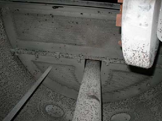
After the cargo containment perhaps the most important parts of an LNG carrier are the systems that handle the cargo. These include the various spaces in which the equipment is located such as compressor rooms and motor rooms. Then the equipment itself: cargo compressors (Pic. 9), vaporisers, cargo and fuel gas heaters, steam and condensate piping systems, cargo and spray pumps (Pic. 10), cargo piping and accessories such as expansion joints sliding feet and clamps.
There are also the cargo valves and control systems and the various relief valves for tanks, voids/barrier spaces and cargo lines. In addition some very important sub- systems are included here such as the nitrogen system, production, storage and distribution and the Inert gas system along with the systems for cooling and drying the inert gas. There are also some specialist systems dependent upon the type of vessel such as the cofferdam heating system.
In all cases each piece of equipment or system is subject to a full and thorough inspection with dismantling if considered necessary. Then a full functional test is carried out to ensure the item or system operates as designed and that all the necessary safety systems and alarms are fully functional.
There is one item which will be observed in operation and functionally tested but will not be otherwise interfered with, that is the custody transfer system. Comment will be passed upon the general condition and it will be rated however as it is a very specialised system any further investigation will only be carried out if the owners specialist or manufacturers representative is present.
Safety Systems
Safety systems form part of virtually every piece of equipment on an LNG carrier and are associated with almost every operation on board. For all items of machinery, the function of the trips alarms and shut downs will be tested as part of the inspection of those particular pieces of equipment or system. There are however large systems which are treated as specific safety items. They can be separated into the normal systems that would be fitted on board any ship, and those specific to LNG carriers.
The normal safety and evacuation gear such as:
- lifeboats,
- falls,
- davits,
- lifebuoys,
- lifejackets,
- immersion suits,
- breathing apparatus,
- fire detection,
- fire fighting equipment;
- CO2 flooding,
- emergency generator,
- emergency fire pump etc.
These are all examined and functionally tested as possible. They are rated in accordance with the general rating criteria, these items are not particular to LNG CAP and are covered and reported on in accordance with the BV Harmonised Condition Assessment Program.
The specific items for LNG Carriers include the List of the Emergency Situations which can happen on the Liquefied Gas Carriergas detection system, the dry powder fire fighting system, the deluge system, fusible plugs and the cargo emergency shut down system.
The gas detection system is of particular importance and it must be proven that it is working properly and sampling from the actual sample point.
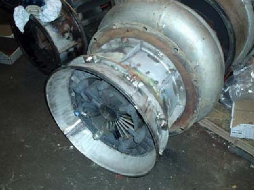
The dry powder system also needs to be fully examined. There can be two types of system often on the same ship. The independent skid mounted unit (Pic. 11) which has a relatively small amount of powder 500 to 1 000 kg, or the large central unit with several tonnes of powder supplying a number of hand held guns (Pic. 12).
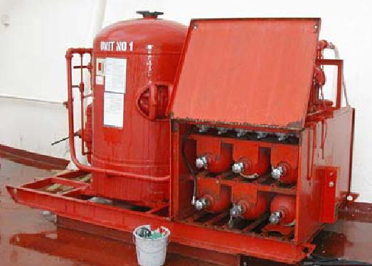
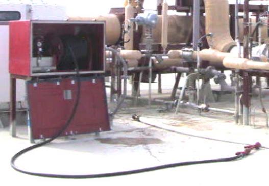
Of prime importance is to ensure that the powder condition is acceptable and free to run, not caked and solid. Additionally the nitrogen cylinders and their flexible hoses will need examination especially if they are located on the open deck (in some cases the flag state has very specific requirements governing gas cylinders). Random testing of the dry powder system is expected. The general rating criteria are applied.
Regarding the deluge system, usually these are straight forward but on older vessels may have been retrofitted. Some systems may be manually operated others may be remote control. It will be necessary to functionally test each part of the system to see that it works as per the requirements of the Gas Code. The main problem with such systems is clogging with broken shell. The general rating criteria are applied.
The cargo emergence shut down can be witnessed at the beginning of loading or discharge.
Propulsion
These days LNG carriers are quite unique in that they are the only vessel still being ordered with steam turbine propulsion. Of course there are very good reasons why this is the case but at last diesel machinery is finally being proposed for this last bastion of the steam age (Pic. 13).
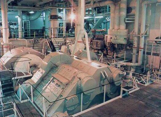
The basic elements of a steam plant are very reliable requiring little in the way of maintenance and this perhaps can be a problem. For inexperienced staff the difference between very little maintenance and none is not a big step but it can lead to severe problems.
The LNG CAP goes into great detail regarding the main and auxiliary machinery.
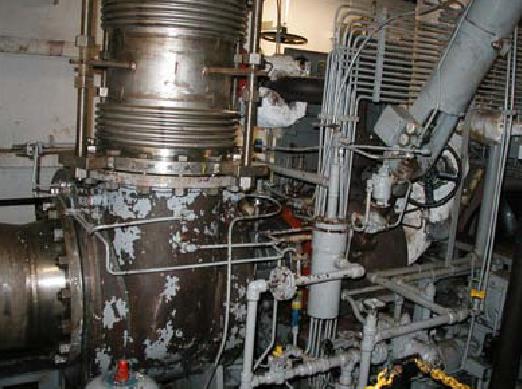
Boilers
The boilers are perhaps where most difficulties occur with older LNG carriers. Due in part to the dual fuel system where on older combustion control systems it is easy to overload the boilers, but also to the lack of experience available amongst some of todays sea staff. From our experience, the greatest problems occur with superheaters (Pic. 14) followed closely by contamination (Pic. 15). The equipment such as burners (Pic. 16), valves and relief valves are usually very reliable and robust.
An important part of boiler operation are the records of water testing and treatment, these records are examined and reviewed to reveal the operational history of the plant.
The boilers are considered so important that every part is subject to different rating criteria such as drums, tubes & down comers, headers, furnace, superheater, economiser, air heater, soot blowers, safety valves, gauge glasses, level control, stop valves, fuel system gas & oil, and finally automatic control.
For each boiler the individual ratings are combined into an overall rating for that boiler.
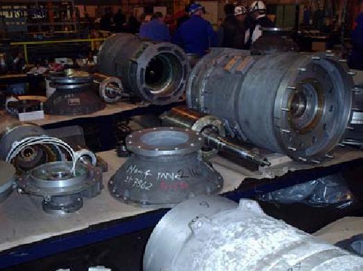
Main Turbine
The main turbines are usually very reliable and may continue quite satisfactorily for many years. The only areas that must be watched are the bearings for wear, the same for flexible couplings. Carry over contamination on the blading (Pic. 17) and erosion on the last stages of the LP turbine (Pic. 18).

Specific criteria are applied to the main turbine depending on the degree of examination, the tolerances found and what rectification work was carried out.

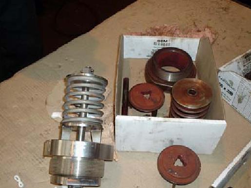
Main Gearbox
Similarly to the main turbines the gearboxes usually operate without problems throughout the life of the vessel. There have been a few notable exceptions recently but these can be put down to initial manufacturing faults rather than long term reliability problems.
For the CAP it is not necessary to fully open the gearbox however the inspection doors need to be removed for inspection. Photographs are taken of representative teeth of the accessible wheels for records especially where the teeth have been tested for contact using a marker dye. Special attention is paid to the tooth ends for any evidence of cracking (Pic. 19). Flaking, pitting and spalling can occur, and if this is found a more detailed inspection will be required, particularly where the pitting is progressive.

In addition, a lub oil analysis is to be conducted and compared with the results from the last two or more previous results. The lub oil pump should be started to verify the condition of the nozzles, where possible. The Gearbox has its own rating criteria.
In addition the main propulsion shafting, bearings and stern tube must be examined and will be rated according to their own rating criteria.
Main Condenser
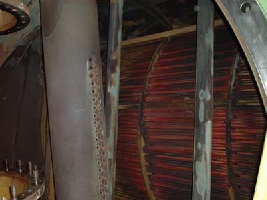
The main condenser is often the source of salt contamination particularly in older vessels. There are a number of possible causes ranging from vibration of the tubes in the support plates, erosion of the tube mouths, steam erosion from the steam dump pipe (Pic. 20) and always the possibility of corrosion.
The condenser must be fully opened for the LNG CAP and will be individually rated.
Feed System
The feed system is generally examined and the records of feed water treatment reviewed, the deaerator has its own rating criteria but the general rating criteria are used for all other pumps, pipes, tanks, coolers and heaters.
Auxiliary Equipment
The auxiliary equipment and systems are dealt with in a similar manner to the major items. The principal is that the equipment need not be opened especially for inspection but it must be functionally tested to full load. This is very important for generators on older ships, both turbine and diesel. There are rating criteria for some of the major auxiliaries such as generators, but others such as Evaporators, Air compressors & receivers, Heat exchangers, purifiers, engine room pumps and piping systems follow the general rating criteria.
Electrical & Instrumentation
The ratings for the electrical systems are based upon inspection and testing results combined with the megger test readings.
For all electrical systems the megger reading criteria are as follows:
- Rating 1, over 100 Meg. ohms;
- Rating 2, 20-100 Meg. ohms;
- Rating 3, over class requirements but less than 20 Meg. ohms;
- Rating 4, below minimum class requirements.
Generation
LNG carriers have large generation capacity. Most capacity is used in port during cargo operations when cargo and ballast pumps are in use. Other large consumers can be gas compressors if these are electrically driven.
Each generator will be tested at full load or as near full load as possible. All electrical trips and alarms will be tested and proven operational at the correct settings. If necessary each generator will be opened for further examination of the windings, air gaps, any slip rings and brushes, air filters and air coolers. The condition of the air coolers and any leakage warning devices is to be ascertained.
Each generator will be megger tested with a high voltage megger and the results will be incorporated into the rating.
Distribution
The condition of all parts of the distribution system are closely examined:
- Switchboards;
- Cabling;
- Starter boxes;
- Transformers;
- Earthing/bonding wires and connections;
- Batteries.
Any problem with switch boards is usually due to obsolescence and difficulty in finding spare parts for breakers and controls.
Program for the switch boards:
- Switchboards to be cleaned, dust vacuum cleaned, all connections and assemblies which may slack tightened. locking devices shall be properly fitted (locking washers, varnish between threaded spindles, nuts, etc.);
- Circuit breakers shall be examined and other types of switches and fuses;
- If necessary reconditioning or replacement of contacts and arc screens will be carried out. The settings and adjustments of trips will be checked;
- If considered necessary measuring instruments shall be examined in a repair shop and calibrated if considered to be inaccurate by the ship’s engineers;
- Breakers shall be serviced;
- An infrared analysis can be used to identify bad connections or elements creating hot spots.
Additional for Emergency Switchboard:
- Testing of the automatic start of the emergency generators, if applicable.
Often the main cause for concern are the cables on the main deck (Pic. 22) providing power to cargo pumps, compressors and control rooms.
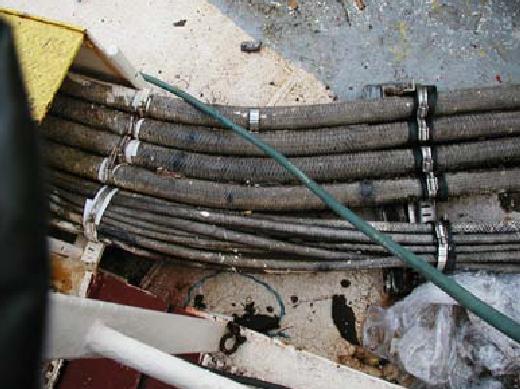
The cables are carefully examined and it is determined if any external braiding is actually the protection, or if further greater protection such as armouring exists underneath. If there are cable runs inside conduits, troughs or trunks , it will be necessary to check as far as possible that these are free from moisture, can drain properly and that the expansion arrangements are free and work. It is also necessary to check the cable ends, and the intermediate junction boxes.
The cabling is assessed under its own criteria the main
part of which must be the results of the megger testing.
Instrumentation
Control and instrumentation is a major part of any LNG carrier operation and can be found everywhere from cargo operations to propulsion, from air conditioning to sanitary disposal. For the smooth and safe operation of these vessels with the limited numbers of crew available the control and instrumentation systems must work. The following items will be examined:
- Remote control devices to allow the starting, stop, speed adjustment or other operations from one or several control positions fitted for this purpose.
- Automatic regulating devices to maintain satisfactory operating conditions for machinery.
- Automatic monitoring systems to warn those in charge, in case of failure.
- Automatic safety devices intended to take immediate action to protect without waiting for engineers’ intervention.
- Local, or remote indications to show the position of machinery parts (when this position cannot be directly monitored) to indicate the value of several parameters.
- Automatic start of stand-by pumps.
- Sequential restart of plant after power failure.
In general a random selection of the monitoring devices will be subject to detailed test and calibration. In addition alarm and shut down systems for cargo machinery, propulsion machinery and auxiliary equipment will be tested to ensure correct operation.
Ship Inspection
There is a huge amount of inspection and testing associated with the LNG Condition Assessment Program and to ensure every part is properly covered the whole process must be very carefully managed. The process take a lot of time and resources, and for many, particularly those on board, it can be particularly difficult and inconvenient. So proper planning and preparation is essential.
It is recommended that the planning phase starts before a surveyor sets foot on board the ship. The first task is to collect all the necessary information for the hull assessment. The hull assessment will be a guide to which areas of the hull structure will require close up inspection. Once the hull structural assessment is complete, and any difficulties and problems are known, then the inspection regime can be developed. The requirement is for the surveyor to see all parts of the machinery and equipment in operation.
Read also: Manning and Operational Standards for the Liquefied Gas Carriers
It is therefore normal for the surveyor to join the vessel at the loading port before dry dock. He will stay on board the vessel during the loaded passage, during the discharge. Later he will join during the preparations for dry docking including the warm up, inerting, and gas freeing. He will then attend the vessel in time to see the cool down in preparation for loading.
In this way it is possible to see all of the cargo systems in operation:
- cargo pumps,
- cargo piping,
- cargo valves,
- cargo compressors,
- cargo warm up heaters,
- vaporisers,
- fuel gas heaters,
- gas detection,
- shut down systems,
- inert gas & dry air,
- nitrogen system.
Also during the period on board the surveyor can examine the hull structure and see other machinery, equipment and systems running and see them tested as necessary.
To ensure that the inspections on board run smoothly, it is strongly recommended that a company superintendent or representative attends on board with the surveyor. Not only will this make the conducting of the inspections on board much easier, it will also provide the company with first hand information regarding the condition of specific areas and equipment.
To get the best possible benefit from the LNG CAP process it is essential that the company and those on board are fully prepared to carry out all of the examination and testing required by the part of the program that they have selected to follow.
Reporting
The reporting is in the standard format already given in guidance note NI 465. As the LNG CAP is completely voluntary the owner may select which parts he requires carried out:
- Hull structure;
- Hull fittings;
- Cargo Containment;
- Cargo installation;
- Machinery installation.
The reports will only refer to and cover the areas requested. (Pic. 23):

The first part of the report is a review of what was covered in the program along with basic details of the ship concerned. This first part also gives details of any recommendations outstanding before the CAP program was started and any recommendations as a result of the CAP program.
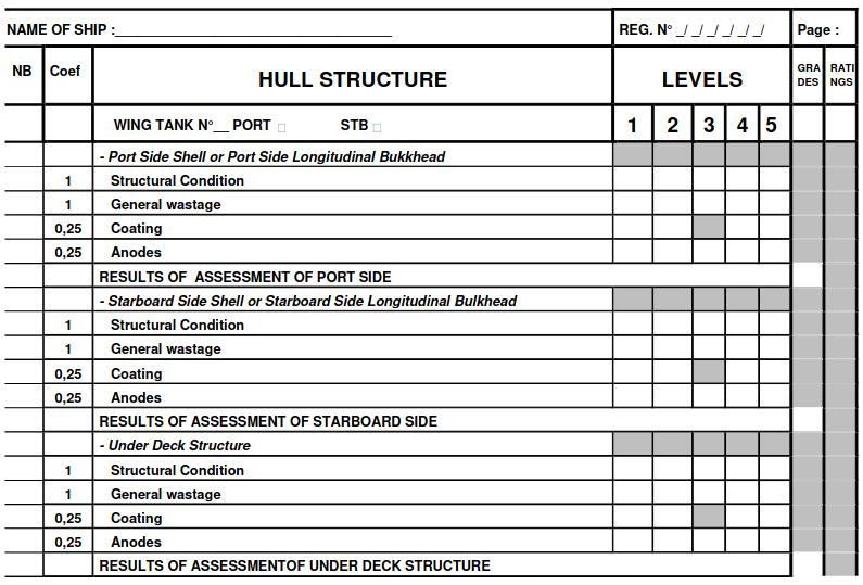
The second part of the report consists of the rating analysis sheets for every part of the vessel that is being considered. From this part it is possible to determine the individual rating for a piece of equipment or section of the structure and see also the global rating in that area see example (Pic. 24).
The final part of the report consists of the certificate (Pic. 25).

Conclusions
From what we have seen at Bureau Veritas, there is a very strong demand from the industry for a thorough condition assessment of older LNG Carriers. We believe that this demand can only become greater as more operators of such vessels, without significant experience, place their vessels in the charter market. The LNG CAP is a service to such owners enabling them to show to a sceptical industry that their vessels remain in fully operational and safe condition.
Currently, a rating of CAP 1 or CAP 2 is considered acceptable to the oil majors. There is no reason to believe that this will change.
Based upon the return of experience already received there are some quite interesting results.
In general, apart from the well documented original difficulties with the type of knuckle fitted to some of the earlier LNG carriers, the hulls of LNG carriers seem to be in good condition.
The problems that have been found tend to be associated with equipment and machinery. This is of course partly due to the obsolescence of that equipment making the availability of spare parts more difficult. It might however indicate a failure to follow proper operational procedures and poor maintenance perhaps due to the lack of experience of some staff.
Although it is not the intention of the LNG CAP program to comment upon the operation of the ships. The results of the CAP can give a good insight as to the results of those operations.