LNG Carrier Safety is a critical concern for the maritime industry, as the transportation of liquefied natural gas by sea poses unique risks and challenges. Ensuring the safe operation of LNG carriers requires a comprehensive approach that encompasses design, construction and operational considerations.
- Dome Arrangement
- Cofferdam Heating System
- General Arrangement
- Heating Coils
- System Operation
- Hull Ventilation System and Cofferdam Arrangement
- Ventilation
- Cofferdam Arrangement
- Interbarrier Space Drain System
- Main Feature
- Operation
- Insulation Space Water Drain System
- Main Features
- Insulation Space Water Discharge
- Jettison
- Fire Fighting Systems
- Fire and Wash Deck System
- Water Spray System
- Dry Power System
- CO2 System
- Fire Fighting Systems on other Projects
Effective LNG Carrier Safety relies on the careful integration of multiple key systems, including cargo containment, propulsion and safety management. By understanding the design and operational requirements of these systems, shipowners, operators and regulators can work together to minimize the risks associated with LNG transportation and promote a culture of safety at sea.
Dome Arrangement
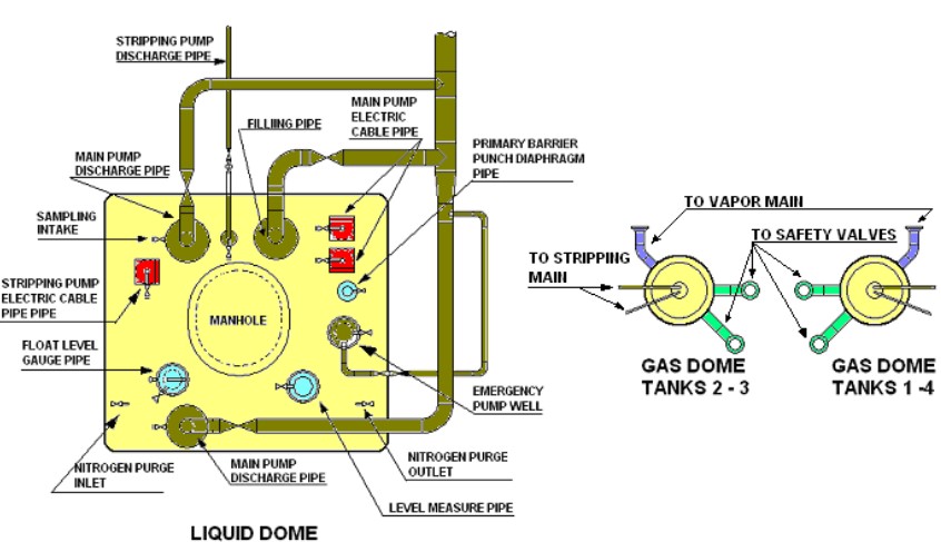
As already mentioned the tank domes accommodate most of the equipment necessary for the cargo handling. This is a short summary of the items arranged in the dome.
The vapor main lines are connected to the vapor dome of each tank. The vapor domes also house the N2 exhaust control valves for the interbarrier spaces, which also includes a set of relief valves from interbarrier spaces. Additionally there are pressure pick up and sample points. The stripping/spray, liquid line and vapor mains have branches to and from the cargo machinery room with connections to the compressors, heaters and vaporizer for various auxiliary functions. Removable bends are supplied for fitting where necessary to allow cross-connection between the various pipe work for infrequent uses such as preparing for dry dock and recommissioning after dry dock.
Figure 1 shows a typical dome arrangement.
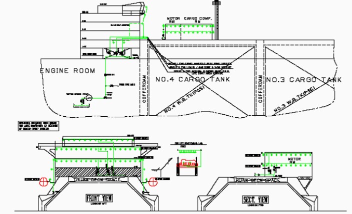
Cofferdam Heating System
General Arrangement
The purpose of this system is to ensure that the cofferdam is kept at all times at 5 °C, when Independent Cargo Tanksthe cargo tanks are in a cold condition. Each cofferdam is heated by two independent systems; one is in service, while the other is on standby.
The maximum heating condition is determined by the following extreme operating conditions:
- external air temperature -18 °C;
- sea water temperature 0 °C.
Any failure of the cofferdam heating system with cargo on board must be treated as serious and proper action is to be effected immediately. In the case of suspected leaks, regular soundings of the cofferdams will indicate into which space glycol water is leaking.
Each cofferdam is fitted with temperature sensors (generally three) on each forward and aft bulkhead, which will also give an early indication of a heating tube failure.
Any accumulation of water in the cofferdam areas can be pumped out using the pneumatic operated water drain pumps, which are located in the forward and after 5 cofferdam spaces.
Figure 2 shows a typical heating arrangement.
Heating Coils
A temperature element on the outlet side of each cofferdam heater and down stream of the three-way flow control valve measures the actual temperature of the glycol water and relays the signal to the integrated automation system. This signal is then processed and a correction value is sent to the heater glycol bypass control valve to maintain the required temperature.
System Operation
Glycol water is circulated through the system of heaters (electric or steam) by means of a circulating pump (one in use and the other on standby).
Expansion, within the system, is allowed for by an expansion tank to which topping up or filling can also be achieved. The required glycol water make-up is made by a pneumatic pump taking suction from a mixing tank. Reserve glycol from a header tank is run down and mixed with fresh water prior to being fed into the expansion tank. The glycol to water ratio is 45 %.
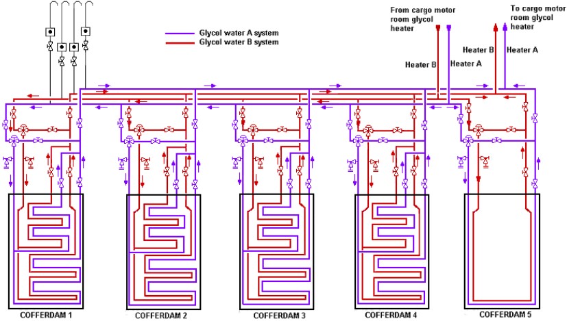
The cofferdam spaces each have two sets of heating coils. The flow of glycol water to each set of heating coils is through a three-way valve and a throttling valve. The second standby set can be put into service immediately. It is connected to the running system by a crossover at the pump suction and at the heater outlets.
The automatic temperature control to each circuit is controlled by three-way valves adjusting the temperature as required. The temperature of the electric heater is controlled by the number of resistors, which are put in service.
The automatic flow control to each cofferdam and liquid dome is achieved by means of a three-way valve on each header. The operating signals for regulation is from automation mimic. Throttling valves on each header return line are set after conducting trials and should not be adjusted unless in a critical situation. Figure 3 shows the diagram of the glycol system.

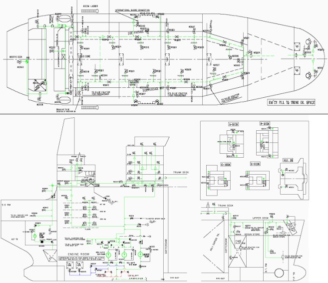
Hull Ventilation System and Cofferdam Arrangement
Ventilation
The cofferdams and pipe duct are inspected on a regular basis in order to check for cold spots, condition of the paintwork and general inspection of piping, fittings and valves. One cofferdam area per month should be inspected.
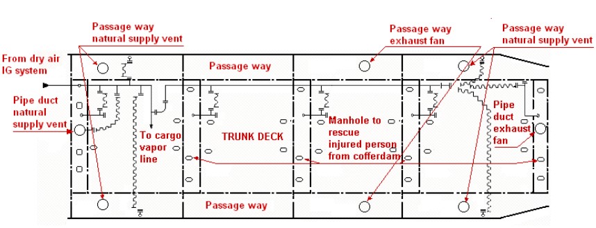
Before entering the cofferdam/pipe duct spaces, the compartments must first be ventilated. In order to ventilate these spaces, a mechanical exhaust fan, which is situated forward above the forward cofferdam, is activated. Above the after cofferdam there is a natural supply mushroom vent, which must be opened before starting the exhaust fan.
Figure 4 shows a typical ventilation arrangement in cargo space.
Cofferdam Arrangement
Each cofferdam is fitted with a manhole cover, which maybe removed and a portable gas freeing fan fitted to which is attached a flexible ducting. This is also the location that any injured person can be removed from the cofferdam space.
On the port side of each cofferdam is a fixed pipe work installation, which leads to the base of the tank, onto which a portable gas-freeing fan can also be fitted.
A stub piece on the side of the pipe is flanged and blanked, its purpose is to be able to connect up to the dry air inert/gas supply via a flexible pipe. There are two portable supply fans for the cofferdam spaces on board the ship. A typical figure of the required total air flow for a ship ranging between 135 000 and
150 000 m3 capacity is of 24 000 m3/h.
The passageway areas, port and starboard, are equipped with a mechanical exhaust fan located midships and two mushroom natural supply vents forward and aft. The passageway areas have the capability of being connected to the dry air inert gas emergency vent line via four blanked off stub pieces welded to the deck, two port and two starboard, and a suitable flexible hose.
The trunk deck areas have four manhole covers, two forward and two aft. The aft manholes are used to fit a portable supply fan for gas freeing, with the forward manholes being removed for exhausting during gas freeing.
Interbarrier Space Drain System
Main Feature
LNG in the bottom of Interbarrier Space Protection: Pressurization, Inertization and Scaffolding Techniquesthe interbarrier space is removed through a number of nitrogen inlet tubes (8 in general) at the aft end of each liquid dome. During the discharge of the affected cargo tank the portable elbow bend is swung and connected to the spray header at the blank flange connection provided on each tank (see Figure 5).
The low duty compressor is set to draw from the spray header through the forcing vaporizer and to discharge to atmosphere through the forward vent mast. The vaporizer, which is steam heated, is used to vaporize the LNG prior to entering the compressor and protects the rotors from any LNG carry over.
An increase in pressure due to vapor leakage will be less obvious than an increase due to liquid leakage. This is because the volume of vapor passing through a fracture is small compared to the volume of liquid, which subsequently vaporizes, passing through the same fracture. In both cases the volumes are likely to be small in comparison with the volume of the interbarrier space.
Operation
Followings are the main operations to be carried out to drain LNG:
- isolate the nitrogen supply to the interbarrier space of tank involved;
- ensure the spray header is shut down and drained of LNG;
- connect the portable elbow bend between the nitrogen header and the spray header;
- open valves inlet and outlet to the forcing vaporizer;
- open valves on low duty compressor to vapor header.
The gas lift LNG removal system is designed to discharge LNG from an interbarrier space, so that the level in this space will reduce at approximately the same rate as the level in a cargo tank where a single pump is running at its designe.
GT96 Membrane System Installation Protocols for LNG ContainmentMembrane ships with GT96 system, in case of emergency due to leak of cargo interbarrier space, means are provided in the domes to punch an hole in the primary barrier. This hole, allowing the cargo to enter the interbarrier spaces equalize the pressure on the both sides of the primary membrane, thus avoid further damages.
Insulation Space Water Drain System
Main Features
Ballast water leakage from the wing tanks to the insulation spaces can occur through fractures in the inner hull plating. If the leakage remains undetected and water accumulates in these spaces, ice accumulation can occur and cause deformation and possible rupture of the insulation. The resultant cold conduction paths forming in the insulation will cause cold spots to form on the inner hull.
The pressure differential caused by the head of water building up in the insulation space may be sufficient to deform or even collapse the membrane into the cargo tank.
To reduce the risk of damage from leakage, each cargo insulation space is provided with water detection units. A bilge piping system connected to two pneumatic pumps is used for the removal of any water.
Insulation Space Water Discharge
Each bilge well is connected to a drain pipe system and pumped by one of two pneumatic pumps located in duct keel.
Each bilge well is connected to a draining pipe system with a pneumatic pump situated in the forward and aft cofferdams for discharging the water to deck level and then overboard by means of a flexible hose (see Figure 6).
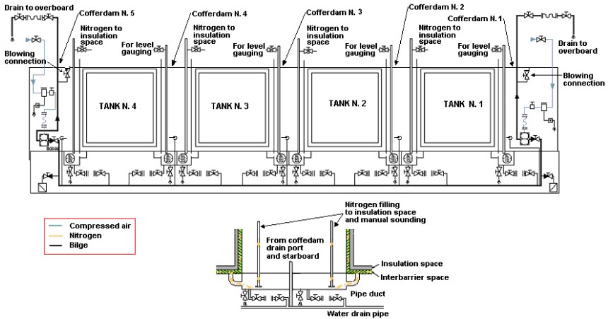
If ballast water is suspected of having leaked into an insulation space the following is to be carried out:
- pump out the ballast water from adjacent wing tanks;
- ventilate the pipe duct space, which runs beneath the cargo tanks and cofferdams and carry out normal enclosed space safety procedures;
- discharge water from a bilge well in order to be able to fit a spool piece between the bilge well drain outlet valve and the draining pipe inlet valve. This spool piece is not normally left in position;
- connect a flexible hose to the pump outlet valve, forward or aft, for drain water discharge overboard;
- open the bilge well outlet and draining pipe inlet valves on the selected tank insulation space;
- open the inlet and outlet valves on the selected pump;
- open the air supply to the pump, continue pumping until the maximum amount of water has been discharged.
After the maximum possible water has been discharged from the insulation space, appreciable moisture will remain in the insulation and over the bottom area. Increasing the flow of nitrogen through the space can assist drying out the insulation. This should be continued until the moisture level is below that
detected by the water detection system before any cargo is carried in the affected tank.
Jettison
A membrane or insulation failure in one or more cargo tanks may necessitate the jettisoning of cargo from that particular cargo tank to the sea. This is carried out using a single main cargo pump, discharging LNG through a portable nozzle fitted at ships manifold. Jettisoning of LNG will create hazardous conditions:
- The discharge rate must be limited to the capacity of one cargo pump only and, if necessary, reduced to allow acceptable dispersal within the limits of the prevailing weather conditions.
- Jettison is not a requirement and not all LNGC are equipped with a Jettison system.
Fire Fighting Systems
Fire and Wash Deck System
The fire main system (see Figure 7) is supplied from the engine room, by the two bilge, fire and the general service pumps. They are two speed centrifugal pumps.
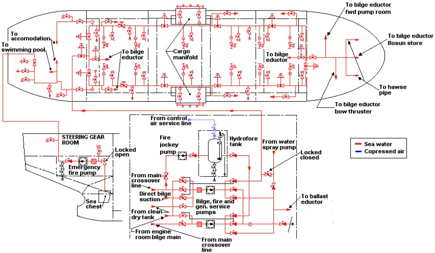
The emergency fire pump is a self-priming centrifugal pump with its own direct sea suction. It is supplied from the emergency switchboard.
In order to prevent bilge water being directed onto the fire main, interlock valves are fitted. When the fire, bilge and general service pump fire main discharge isolators are opened, a pressure signal is sent to the pump bilge suction isolators. This signal acts upon an actuator and thereby ensures that the bilge valve closes and cannot be opened until the fire main isolator is closed.
The fire main is kept pressurized by hydrophore tank and a topping up pump. The topping up pump has an automatic pressure cut in/out switch. The fire main is kept topped up and under pressure at all times.
The deck fire main has a main isolator valve, before the port and starboard main ring main isolator valves. The ring main is fitted with a further four section isolator valves on each side at regular intervals along up the deck, before the forward deck ring main crossover isolating valve. This is to allow any part
of the system to be supplied from either side of the ship.
The fire main also serves the water curtain below the port and starboard manifold areas during loading and unloading conditions. The fire main supplies the driving water:
- for the bilge ejectors in the pipe trunk-way;
- duct keel pipe duct;
- forward pump room;
- bow thrust room and bosun’s store.
Under normal operating conditions, the fire main will be under pressure during port time, supplying the manifold water curtain and with hoses run out as a fire precaution.
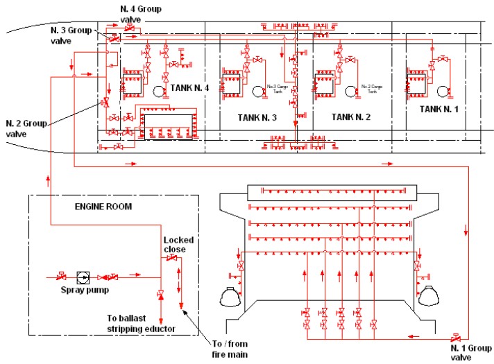
Water Spray System
The accommodation block front, compressor house, cargo tank liquid and vapor domes and manifold areas are protected by water spray from the effects of fire, gas leakage or liquid spill.
There is a spray pump, mounted on the engine room floor level, delivering to spray rails across the accommodation block front, lifeboat embarkation areas port and starboard, compressor house sides and deck domes/manifolds.
They are normally grouped into four sections as follows:
- Group 1 Accommodation and lifeboat embarkation area.
- Group 2 Cargo machinery and electric motor room.
- Group 3 Cargo liquid dome, cargo vapor dome.
- Group 4 Cargo manifold.
Each group main spray rail has a remotely operated hydraulic isolating valve operated from the fire control room. The spray pump can be started locally and from the wheelhouse via IAS mimic, CACC via IAS mimic, on the main deck close to the accommodation exits and fire control station on U deck.
Each main group is sub-divided into smaller sections, with a flow regulating and section isolating valve fitted. In an existing application the accommodation front is covered by five such sub sections, beginning at deck level C, right through to the navigation/bridge deck. The decks below C deck will have sufficient flow passing over them that they do not need to be covered by a fixed rail.
Figure 8 shows the spray system for the accommodation front.
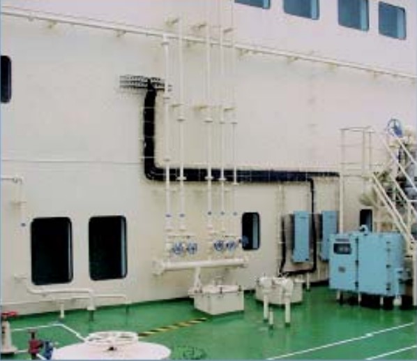
Figure 9 the complete diagram of the system.
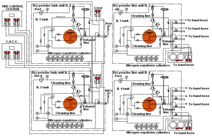
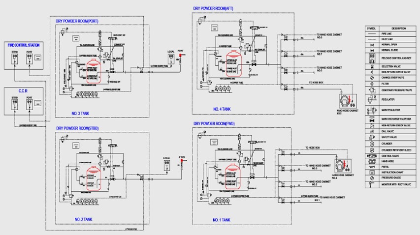
Dry Power System
The dry powder firefighting system consists of 4 separate units.
a) MAIN SYSTEM
Two dry powder units are situated on the main deck midships, one port and one starboard. Each unit contains a 1 518 kg dry powder storage tank, 8 nitrogen expellant cylinders of 68 liter each and a single dry powder monitor with an outreach of 250 m.
Operation of the system can be carried out from a cabinet in the fire control room, CACC and locally. Activation of the nitrogen pilot cylinders in the cabinets allows the high pressure gas to flow into the main valve (before the monitor) actuator, thereby causing the valve to open. The nitrogen is then led to the release mechanism for the expulsion of the nitrogen from the storage cylinders.
The high pressure nitrogen cylinders are released and the media flows into the main dry powder tank through an upper and lower injection pipe. When the tank pressure has reached a sufficient pressure, a pressure release valve operates, thereby allowing the residual nitrogen in the expellant pipes to open the main outlet from the tank. Operation of the manual valve at the monitor will now allow the dry powder to be used as required.
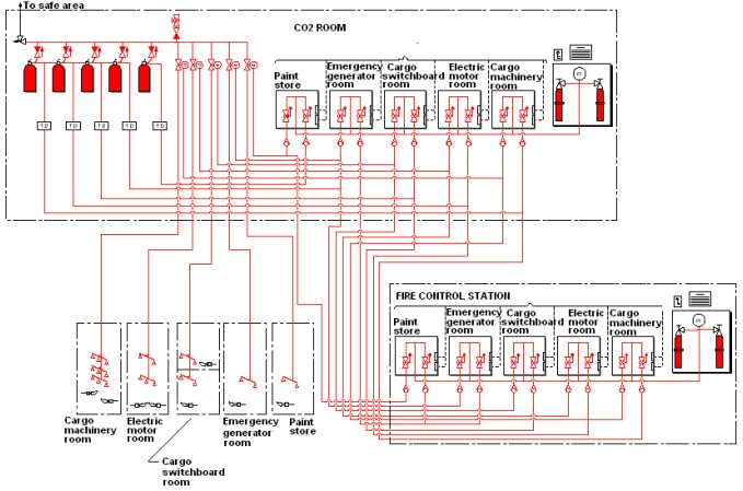
CO2 System
The deck CO2 system covers the following areas:
- cargo machinery room;
- electric motors room;
- cargo switchboard room;
- emergency generator room;
- paint store.
Flooding of the protected areas is achieved by the operation of the ball valves from their respective cabinet in the fire control station or CO2 room and the release of the pilot CO2 cylinders. Upon opening the control cabinet door, the CO2 alarm is activated and the ventilation fans for that area are stopped. The pilot gas is directed by the operation of the respective ball valve, onto the release line (having first operated the time delay switch down stream of the high pressure cylinders) and master valve for the selected area.
The emergency generator room and paint store both share the same CO2 cylinders, although they have a separate main discharge line to their space. See Figure 11.
Fire Fighting Systems on other Projects
The complete fire fighting system described above is a typical installation on an existing 138 000 m3 LNGC’s. However this system can be considered typical for all LNGC’s. The following Figures 48, 49 and 50 show the fire main, the spray line and the powder system of Top LNG Carrier Builders in Marine Industrya typical LNGC built by another shipyard.
From the comparison of the two sets of diagrams it is possible to realize how similar are the two systems.

- The Society of International Gas Tanker and Terminal Operators (SIGTTO). Liquefied Gas Handling Principles on Ships and in Terminals (LGHP4) / 4th Edition: 2021.
- The international group of liquefied natural gas importers (GIIGNL). LNG custody transfer handbook / 6th Edition: 2020-2021.
- American Gas Association, Gas Supply Review, 5 (February 1977).
- ©Witherby Publishing Group Ltd. LNG Shipping Knowledge / 3rd Edition: 2008-2020.
- CBS Publishers & Distributors Pvt Ltd. Design of LPG and LNG Jetties with Navigation and Risk Analysis / 4th Edition.
- NATURAL GAS PROCESSING & ITS ENERGY TRANSITION ROLE: LNG, CNG, LPG & NGL Paperback – Large Print, November 14, 2023.
- American Gas Association, Gas Supply Review, 5 (February 1977).
- The Society of International Gas Tanker and Terminal Operators (SIGTTO). Ship/Shore Interface / 1st Edition, 2018.
- Department of Transportation, US Coast Guard, Liquefied Natural Gas, Views and Practices Policy and Safety, p. IV-3.
- Department of Transportation, US Coast Guard, Liquefied Natural Gas, Views and Practices Policy and Safety, p. IV-4.
- Federal Power commission, Trunkline LNG Company et al., Opinion No. 796-A, Docket No s. CP74-138-140 (Washington, D. C.: Federal Power Commission, June 30, 1977).
- Federal Power Commission, Final Environmental Impact Statement Calcasieu LNG Project Trunkline LNG Company Docket No. CP74-138 et al., (Washington, D. C.: Federal Power Commission, September 1976).
- Federal Power Commission, «FPC Judge Approves Importation of Indonesia LNG».
- OCIMF, ICS, SIGTTO & CDI. Ship to Ship Transfer Guide for Petroleum, Chemicals and Liquefied Gases / 1st Edition, 2013.
- Federal Power Commission, «Table of LNG imports and exports for 1976», News Release, June 3, 1977, and Federal Energy Administration, Monthly Energy Review, March 1977.
- Office of Technology Assessment LNG panel meeting, Washington, D. C., June 23, 1977.
- Socio-Economic Systems, Inc., Environmental Impact Report for the Proposed Oxnard LNG Facilities, Safety, Appendix B (Los Angeles, Ca.: Socio-Economic Systems, 1976).
- «LNG Scorecard», Pipeline and Gas Journal 203 (June 1976): 20.
- Dean Hale, «Cold Winter Spurs LNG Activity»: 30.