Unlock the secrets to seamless LNG loading operation with our comprehensive guide. From meticulous preparation and pre-loading operations to bulk rate loading and departure procedures, optimize efficiency and safety every step of the way.
Reference: SIGTTO “LNG Shipping Suggested Competency Standards”, Sections:
1 Have an awareness of the loading procedures:
- CTMS – pre and after complete loading procedures;
- normal “ramp up” and “ramp down” procedures;
- control of LNG flow rate from shore;
- vapour pressure control;
- de-ballasting procedures.
2 Know and understand loading procedures:
- CTMS – pre and after complete loading procedures;
- normal “ramp up” and “ramp down” procedures.
- vapour pressure control:
- H/D compressor;
- “free flow” method;
- tank pressure requirements during loading and explain the reasons why they should be maintained.
- parameters that should be monitored throughout operation and the criteria that may indicate problems;
- valve conditions on completion of loading.
3 Know de-ballasting procedures:
- de-ballast procedure to be implemented to maintain required draught and trim requirements during loading;
- operation of ballast pumps and eductors.
4 Have an awareness of the procedures for cargo line draining:
- principle of line draining.
5 Know and understand the procedures for cargo line draining:
- method of operation for different procedures required for each type of vessel;
- procedure for undertaking line draining using shore’s nitrogen supply;
- procedure for undertaking line draining using ship’s nitrogen supply;
- final manifold condition required prior to disconnecting pipeline.
Loading operation
Ship/shore meeting
Before operations commence, there will be a ship/shore meeting (also referred to as a pre-transfer meeting). This will include subjects such as:
- designation of individuals responsible for the LNG transfer or involved in the operation (ship’s officers, terminal representative, surveyors and others);
- completion of the Ship/Shore Safety Checklist;
- survey and confirmation of cargo tank status, including verification that the LNGC is ready to load;
- the agreed sequences of the cargo transfer operation (these should be planned in advanced in writing).
Cargo records
During operations, cargo records should be maintained according to company and charterer requirements. Documents will be distributed between the interested parties. These include:
- timesheets and Statement of Facts (this is a record of all events concerning the progress of cargo operations and other key events);
- cargo documentation such as certificates of quantity and quality (issued by the loading terminal) and certificate of origin (from the producer/shipper);
- checklists such as the Ship/Shore Safety Checklist (completed prior to commencing operations).
Filling limits
According to Chapter 15.3 of the IGC Code, the default value for the filling limit of cargo tanks is 98 % liquid at the reference temperature. However, there are exceptions for an increased filling limit under 15.4 of the IGC Code. This states that where authorised by the flag State and the Classification Society, filling limits can be increased up to 99,5 % at the reference temperature, subject to the following:
- structural configuration of the LNG tank;
- orientation of the pressure relief valves and vapour return lines within the cargo tank;
- ship movement;
- accuracy of level gauges;
- accuracy of temperature indication;
- accuracy of pressure relief valves;
- strength of the ship structure;
- operational procedures.
Note that, in such cases, the CTMS levels alarms are correspondingly adjusted.
The rationale behind these filling limits is to ensure that the cargo tanks will not become completely full of liquid during normal operations and that the inlets to the pressure relief valves in the vapour space will remain clear under all conditions.
Due to the different tank designs, a membrane type LNGC will have a filling limit less than that of a Moss type LNGC. The individual tank loading valve must be manually closed as limiting volumes are reached. Critical to this procedure is the time that the loading valve takes to close.
The reason why Moss cargo tanks can be loaded to a slightly greater percentage than Cargo Containment Systems of LPG and LNGmembrane tanks is that the surface area of the cargo is greatly reduced as it approaches the maximum filling level and the cargo height can be measured more accurately. The spherical tank shape also ensures that there is less chance of the formation of gas pockets, which may be isolated from their pressure relief valves when the ship is heeled or trimmed.
Preparation for loading
Three or four days prior to arrival at the terminal:
- ensure that a cargo loading and de-ballasting plan is available;
- undertake cargo valve (incl. vent mast) functionality test;
- undertake ballast system valve functionality test;
- portable and personal gas detectors are to be tested and calibrated;
- confirm that all certification lead seals on cargo tank gauges are intact;
- check availability of mooring lines, pennants and winches;
- check and fit manifold short distance (spool) pieces, filters, gaskets and presentation flanges;
- pressure test the liquid and vapour manifolds with N2. Test pressures should be 5 bars at the liquid manifold and 2 bars at the vapour manifold. Use soapy water to detect for leaks.
Two days prior to arrival at the terminal:
- the ESDS must be tested and proven fully operational within 48 hours of arrival in port;
- confirm that all remotely operated valves have been checked and operate within surge avoidance parameters. These should close within 25-30 seconds;
- line up the cargo system and ensure that the intended offshore manifold is secured.
Confirm the following are tested and fully functional:
- cargo tank pressure control systems (GCU, reliquefaction plant, fuel gas where fitted);
- independent cargo tank high level alarm system;
- manifold water curtain;
- fire pump/water spray system;
- HD compressors;
- gas and fire detection equipment.
The Master confirms to the terminal the functionality of the cargo system, GCU, High Duty Compressor(s) on the Liquefied Natural Gas CarriersHD compressors and provides the ballast water exchange form (where applicable).
One day prior to arrival at the terminal:
- pre-arrival meeting (including finalisation of appropriate risk assessments);
- ensure the LNGC is prepared as per the approved ship/shore compatibility study, including manifold connections and mooring layout;
- ensure new gaskets are fitted on/available for all manifold related connections;
- mooring lines laid out and appropriate pennants fitted.
Day of arrival at the terminal:
- adjustment of cargo tank pressure as per terminal requirements;
- ballast adjustment for appropriate arrival draught and trim;
- ensure that all deck scuppers are closed;
- ensure that all deck savealls are dry and clean;
- ensure that stainless steel buckets filled with fresh water are available at cargo tank domes;
- provide an adequate supply of fresh clean rags for use as a temporary method to stem a minor leak;
- prepare the SOPEP equipment;
- prepare deck fire-fighting equipment;
- prepare the international ship/shore fire connection.
On arrival – considerations for all LNGCs:
- the main engine(s) must be isolated (but not immobilised) prior to receiving the gangway;
- in the CCR, set the cargo tank level alarms for the “In Port”/”Harbour” condition.
Pre-loading operations
Ship/shore comms links and cables
- Connect the communication/ESD cable, usually a male/female plug arrangement (fibre optic or electrical) that provides the channels for ship/shore communication and ESD interconnection;
- if required, connect the ESD umbilical cable. This is usually a pneumatic connection;
- ship/shore communication systems should be established and proven operational. These include the mooring tension monitor, hotline and plant phone;
- while ISGOTT does not recommend the use of a ship/shore bonding cable, some terminals still insist on the connection of this cable. In such cases, the ship/shore bonding cable should be checked to ensure it is mechanically sound and clear of the manifold area.
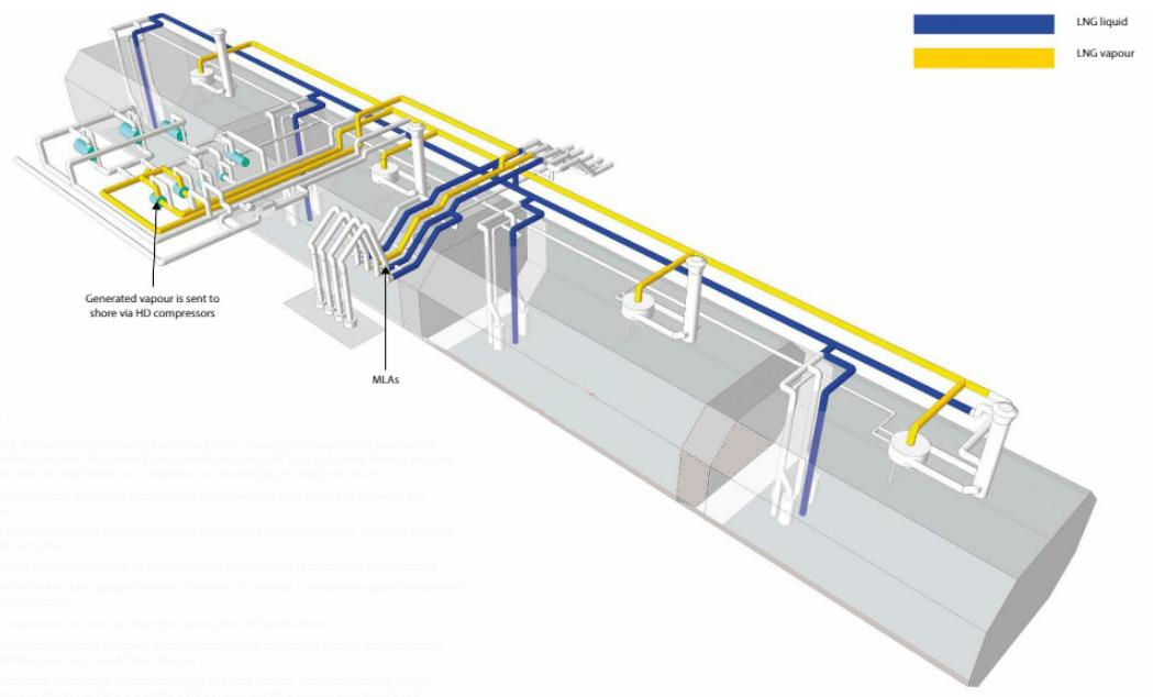
The normal arrangement at most Equipment and cargo system of LNG onshore terminalsLNG export terminals is 3 MLAs and one vapour return arm. The following considerations apply:
- The terminal will require that the ESD manifold valves are closed and blocked and that the double-shut valves are closed before the MLAs are connected;
- when the MLAs have been connected, they are purged with N2 until the O2 level is < 1 % by volume and the dew point < minus 50 °C (-50 °C).
Note: the N2 is typically supplied by the terminal. However, there are certain terminals that will request that the LNGC supplies the N2 for purging and pressure test of the MLAs.
- once the MLAs have been confirmed as having an O2 level < 1 % by volume, they are pressurised with N2 to a pressure of 5 bars in each liquid arm and 2 bars in the vapour arm.
Note: the value of 5 bars on the liquid arms corresponds to the typical maximum allowable working pressure of the manifold.
- the responsible ship’s officer and terminal representative check all associated joints for leakage.
Note: soapy water is still preferred means of leak detection.
- when the MLAs have been proven free of leaks, they are depressurised in a controlled manner;
- ensure the LNGC is upright and on an even keel;
- conduct the opening survey using the custody transfer measurement system (CTMS). Ensure this is in the presence of the Chief Officer, loading master and any cargo surveyor (if appointed);
- the manifold water curtain must be started as soon as the MLAs are connected;
- complete the Ship/Shore Safety Checklist and the ISPS checklist;
- when the LNGC and terminal are ready to carry out ESD tests, confirm whether it is the LNGC or the terminal that will initiate the shutdown.
An insulating flanged section inserted into the loading line is the most effective method of preventing stray current flow.
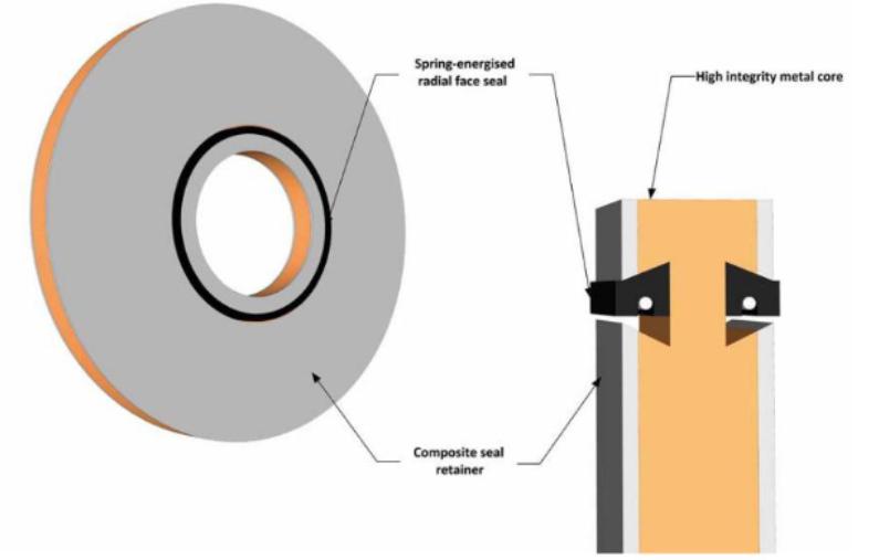
Where an insulating flanged joint is inserted in a loading line, the section of the line from the flanged joint to the ship must be electrically continuous with the ship to prevent the build up of an electrostatic charge due to loading and unloading on metallic connections (e. g., flanges).
Read also: Preparation of loading and unloading operations for LNG/LPG carriers
The section of the line on the shore side of the insulating flange must also be continuously bonded and connected to earth on shore.
ESDs
Two ESD tests may be carried out to verify that the closure ti me of the remote actuated valves will close within 30 seconds. These are:
- a warm test of ESD with pipelines and valves at ambient temperature;
- a cold test of ESD or function test conducted on manifold valves after cooldown.
Once ship and shore have confirmed Emergency Shutdown System (ESDS) on Liquefied Gas Carrierscorrect ESD operation, both can re-open the appropriate valves (manifold/ESD), reset the ESDS and return it to “healthy” status.
The next stage of events is as follows:
- the LNGC may request permission from the terminal to return vapour ashore (associated vapour return lines and valves are set accordingly);
- enable and ensure all cargo tank level alarms are operational.
The LNGC is now ready to commence cargo operations. The cooldown of the MLAs and liquid header is the next step in the procedure.
Cooldown for loading
Assuming that the LNGC has arrived in the cold condition or “ready to load”, the following is the recommended sequence of events:
- ensure the cargo system is correctly lined-up and set for line cooldown;
- request that the terminal starts cooldown;
- in conjunction with the LNGC, the terminal will gradually increase the cooldown rate, simultaneously cooling lines ashore and on the LNGC;
- on deck, the OOW and crew must monitor the cargo system and report the cooldown progress.
Any sign of liquid/vapour leakage must be reported to the CCR immediately.
As an approximation, the Cooldown of Cargo System on the Liquefied Gas Carriersprogress of cooldown is indicated by a sudden reduction in liquid header/crossover temperature and light frosting along the liquid header.
In the CCR, the officer in charge is responsible for monitoring tank pressures, vapour header pressure, liquid header/crossover pressure and temperature. At the same time, the N2 supply to the interbarrier/annular space is closely monitored to ensure the correct pressures are maintained.
Usually, the terminal is the first to report that cooldown is completed. The LNGC will then request the terminal to standby, pending cooldown completion on the LNGC. Line cooldown, as monitored in the CCR, is considered complete when the liquid header temperature attains a prescribed value (this can vary from minus 110 °C (-110 °C) to minus 130 °C (-130 °C), even down to minus 157 °C (-157 °C) in some cargo manuals). The officer in charge (OIC) should ensure that:
- when the cooldown on the LNGC is completed, the terminal is informed and requested to standby in preparation for the commencement of loading;
- the tank filling valves are set according to the approved ship specific cargo plan;
- a cold ESD or manifold valve functionality test is carried out;
- on completion of cooldown, the terminal control is requested to start loading at the agreed rate.
When loading commences, watch for heavy frosting of the cargo pipes on deck as this idicates the presence of liquid LNG within the pipeline.
A watch must be kept at the manifold and a “roving watch” on the tank deck, checking for leaks, etc during the commencement of loading.
If there are any small leaks on the cargo pipework, they must be attended to because any progress to a larger leak would result in cargo being stopped and the area having to be deluged with seawater.
Ramp-up to bulk rate
Ramp-up commences when liquid flow is confirmed at manifold:
- on deck, the OOW and crew continue to monitor the integrity of MLAs, cargo lines, associated flanges and instrument connections/impulse lines;
- when the terminal confirms that loading has commenced, the first HD compressor should be started, returning gas ashore.
The rate is only increased when the LNGC can safely handle the cargo tank pressure.
Note: Terminal liquid lines are of significant length and kept in cold condition by recirculation of LNG. The LNG in the terminal recirculation system will unavoidably be warm, generating significant boil-off. Once cold LNG from the terminal storage tank is received on board, a tank pressure drop will be observed. As a general rule, the amount of LNG in m3 to be loaded before cold cargo is received equals the length of shore liquid line in metres.
Loading continues as follows:
- providing that BOG generation and N2 supply to the interbarrier/annular space are both under control, request the terminal to increase the loading rate up to maximum over the pre-arranged timescale as per the cargo plan;
- start the second HD compressor as necessary;
- with both HD compressors running steadily in parallel, tank pressures are lowered, as agreed during the pre-loading meeting between the ship and terminal.
In the interests of cargo conditioning, commencing loading at the lowest possible pressure appropriate for the containment system is an important factor.
- once the full loading rate is achieved, individual tank filling valves must be adjusted to provide a staggered tank completion, as per the cargo plan;
- as bulk loading progresses, boil-off tends to reduce and it may prove necessary to stop one of the two HD compressors.
Where applicable, the ship will normally be able to burn BOG throughout the loading operation.
Bulk rate loading
During loading:
- in the CCR, an hourly record is maintained of tank levels, quantity on board (QOB), loading rate and Comprehensive Guide to Ship and Shore Preparation and Manifold Connection for LNG Cargo Operationsmanifold pressures. The terminal will normally require QOB, % cargo loaded, loading rate and estimated time of ramp-down and completion, as recorded by the ship every hour;
- the CCR officers must maintain a dose scrutiny on the weather delta (wind and sea state) and moorings;
- loading operations provide the opportunity to log HD compressor parameters. These are normally recorded every hour;
- frequent and thorough checks of an cargo lines and associated equipment must be performed;
- check the secondary tank gauging system, at intervals, to provide a comparison against the primary tank gauging system;
- the HD compressors ate used to return the vapour from the tanks ashore;
- once the full loading rate is achieved, loading valves can be adjusted to prevent flow preference (unequal filing may occur in all LNGC designs);
- the de-ballasting operation is carried out during bulk rate loading. This operation is as critical as loading as it affects the LNGC’s stability and can cause significant issues and delays if not completed. De-ballasting operations require careful planning to ensure completion prior to ramping down. Take care throughout to ensure that a fist does not occur;
- to make it easier to empty the ballast tanks, the ship may be trimmed by the stem within the terminals maximum draught requirements;
- the cargo tanks will be staggered to allow for a rime difference between each of the tanks finishing. This is known as “topping off”;
- boil-off tends to reduce and it may be necessary to stop one of the two HD compressor;
- the officer in charge should give one hour’s notice of the first loading rate reduction to the terminal.
Ramp-down
The OIC should:
- give one hour’s notice to the terminal of the first loading rate reduction (ramp-down). Normally, this would be when the first shore pumps are to be stopped;
- plan to complete de-ballasting approximately one hour before completion of cargo and before topping-off the first tank, ensuring the ship is upright and on an even keel.
The high-high level alarms and shutdowns are emergency devices only and should, on no account, be used as part of the normal topping-off operation.
The following considerations apply:
- the loading rate reduction (ramp-down) is carried out as per the pre-agreed plan exchanged at the pre-loading meeting;
- the terminal will inform the LNGC of their rate reduction procedure and the LNGC will plan to stagger cargo tanks accordingly;
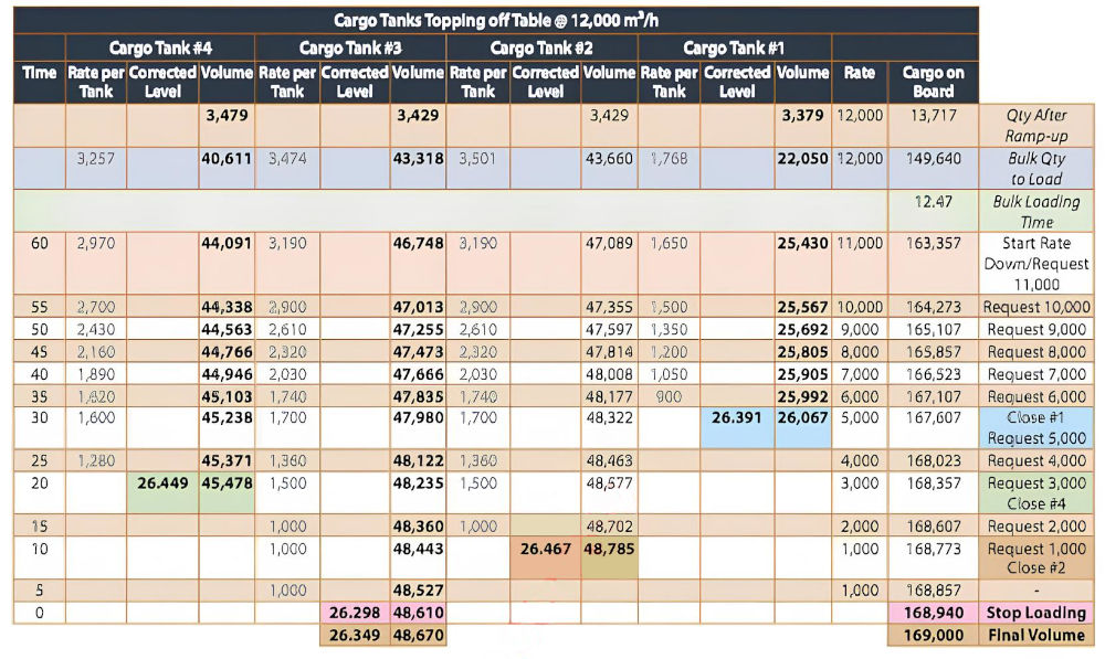
- it is prudent to prepare a topping-off table for ease of reference during operation;
- the majority of LNGCs are equipped with an IAS that provides a trend function. This is particularly useful when topping off the cargo tanks.
As each cargo tank is topped off, the OOW and/or deck rating will be standing by on the tank dome. Their role is to confirm the closure of each tank filling valve and take remedial action in the event that the valve is not operating under remote control.
- as the last cargo tank approaches the final level (less the line drain quantity), request the terminal to stop loading;
- stop the final HD compressor;
- reinstate the BOG management system (either gas burning or reliquefaction);
- once the terminal has confirmed that cargo loading has stopped, and in agreement with the terminal, inhibit the ESDS and close the manifold double-shut valves.
Post-loading operations
- Once loading is complete, line-up and conduct line drainage;
- ensure that the LNGC is upright and on an even keel;
- on completion of draining, and with the terminal’s permission, close the liquid manifold/ESD valves;
- when satisfied that the BOG management system is controlling the cargo tank pressures, inform the terminal and close the vapour to shore valve;
- the loading master will request the terminal to purge the liquid and vapour return line with N2. This procedure purges the MLAs of hydrocarbons. The actual method will vary according to the terminal and LNGC type, but whichever way purging is arranged the principle remains the same. Purging will continue in the approved manner until the CH4 content is reduced to < 1 % by volume;
- the closing statement from the CTMS is conducted in the presence of the Chief Officer, loading master and/or cargo surveyor;
- MLAs are disconnected after final depressurisation;
- the manifold strainers should be inspected for debris, distortion or discolouration.
Departure from load port
- Stow float level gauges, ensuring that the stowed reading is correct;
- the Master and Chief Officer should complete and issue all appropriate paperwork;
- secure and blank the manifold connections;
- with the terminal’s permission, disconnect the ship/shore communication cables and return them ashore;
- stop the manifold water curtain;
- when all terminal personnel have disembarked from the LNGC, ensure the gangway is safely removed;
- in the CCR, set the cargo tank level alarms for sea-going condition.
The ship may then depart. After the LNGC leaves the berth, set the cargo lines to prevent the risk of liquid (or cold vapour) entrapment. While liquid lines are fitted with relief valves at all sections where entrapment may occur, there is no such arrangement on the vapour line.
To reduce the risk of valves sticking in the closed posit ion, it is a good practice that manual cargo valves (cooldown, crossover and double-shut valves) are cracked open to remove the valve from the valve seat for the first 24 hrs after departure.

- The international group of liquefied natural gas importers (GIIGNL). LNG custody transfer handbook / 6th Edition: 2020-2021.
- ©Witherby Publishing Group Ltd. LNG Shipping Knowledge / 3rd Edition: 2008-2020.
- CBS Publishers & Distributors Pvt Ltd. Design of LPG and LNG Jetties with Navigation and Risk Analysis / 4th Edition.
- NATURAL GAS PROCESSING & ITS ENERGY TRANSITION ROLE: LNG, CNG, LPG & NGL Paperback – Large Print, November 14, 2023.
- OCIMF, ICS, SIGTTO & CDI. Ship to Ship Transfer Guide for Petroleum, Chemicals and Liquefied Gases / 1st Edition, 2013.
- The Society of International Gas Tanker and Terminal Operators (SIGTTO). Ship/Shore Interface / 1st Edition, 2018.