Explore the crucial steps of LNG ship and shore preparation, focusing on manifold connection for cargo operations. From terminal requirements to emergency breakout procedures, this guide covers essential safety measures and efficient handling procedures for LNG marine loading arms and manifold equipment.
Reference: SIGTTO “LNG Shipping Suggested Competency Standards”, Sections:
1 Have an awareness of safety procedures. Ship/Shore safety checklist:
- purpose;
- ICS checklist.
2 Know and understanding safety procedures:
- ship/shore safety checklist:
- possible additional port specific requirements.
- content and agenda for pre load and discharge meeting:
- purpose.
3 Know and understand manifold pipeline requirements prior to connection:
- hydrocarbon requirements;
- dryness requirements.
4 Have an awareness of marine loading arms:
- type and construction;
- purpose of safety devices;
- handling procedures;
- emergency breakout operation.
5 Know and understand marine loading arms:
- type and construction;
- purpose of safety devices;
- handling procedures;
- emergency breakout operation.
6 Know and understand manifold filters:
- purpose;
- methods for checks;
- fitting procedures.
For all new LNGCs, compatibility plans are produced for the terminals that the ship is expected to visit. Prior to the initial visit of an LNGC at any terminal, a “compatibility study” is always conducted between the ship operator and the jetty operator.
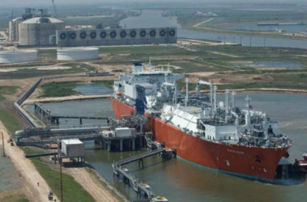
On arrival at a loading or discharge terminal, the Ship/Shore Safety Checklist should be jointly completed by a responsible ship’s officer and the terminal supervisor. Until the safety checklist has been completed, no cargo operation of any description should take place. Each item should be positively verified before it is ticked off.
Incidents still occur during cargo operations that, on investigation, show the safety checklist to have been completed poorly, so the importance of carrying out correct and repeated checks during cargo operations cannot be over-emphasised.
Terminal requirements
These will be indicated to the ship at the ship/shore safety meeting, where the following information will be confirmed/provided:
- a copy of the terminal and local regulations;
- all relevant information about the cargo to be loaded;
- locations of designated smoking areas;
- advice to the ship on approval of any “work” procedures alongside.
It must be ensured that both parties fully understand the procedures in the event of emergency on ship or shore and provide a description of the equipment that is available:
- safe access/gangway arrangements;
- ship/shore communications, in-plant radio systems, etc.;
- ship to provide the terminal with estimated maximum departure draught;
- agree a start-up rate, normal rate and top-off volume and rate if the ship is loading and notice is required by the terminal for stopping the first pump;
- provide details on the LNG cargo to be loaded/discharged, i. e. quantity, temperature, SG, etc.;
- the shore should describe the workings of the emergency shutdown systems, which must include the effective closing time of ESD valves.
Content and agenda for pre-load and discharge meeting
A pre-discharge/loading meeting is held to confirm cargo procedures and exchange relevant information with respect to the ship’s time at the port. Discussing the Ship/Shore Safety Checklist usually takes place as part of this Ship/Shore Interface in Gas tradingship/shore interface meeting. The terminal may also require a safety tour of the ship, which should be provided by a responsible ship’s officer. The Ship/Shore Safety Checklist would typically include the following:
| Ship/Shore Safety Checklist | |
|---|---|
| Main engine state of readiness | Notice required for establishing full standby conditions |
| ISPS Security Level | Gangway details |
| Intended visitors | Technical compatibility |
| Smoking regulations and policy | ESDS test satisfactory (yes/no) |
| CTMS fully functional (yes/no) | Primary and backup means of communication with the terminal |
| Identification of the terminal’s agent/representative on board | Fire main pressurised (yes/no) and the associated pressure |
| Fixed fire-fighting systems operational (yes/no), ready for immediate use | Bunker details (as appropriate) |
| Storing details (as appropriate) | Oil spill response contingency equipment, ready for immediate use |
| OIC identification and contact details | Onboard emergency telephone numbers |
| Key personnel telephone numbers | Any other operations |
| Any known defects | |
If there are any special or specific requirements from either the ship or shore, then the pre-discharge/loading meeting also provides opportunity for these to be raised. These may include, but are not restricted to, the following:
| Special requirements | |
|---|---|
| Quantity of cargo available ashore | Single arm loading/discharge |
| Availability of the return gas blower (RGB) | Maximum pressure on manifold |
| Number of shore personnel to remain on the ship through the cargo operation | CTMS requirements |
| Vapour pressure requirements | Terminal personnel (shift) changes that may affect the ship |
| Anticipated change in loading/discharge rates | Mooring requirements, i. e. tensions |
| Cooldown timing requirements | Cargo topping-off requirements |
| CTMS report acceptance, i. e. quantity ROB, average liquid temperature, etc. | Heel requirements (discharge port only) |
| Ballast requirements and expected pumping times (ballast management/exchange paperwork as appropriate) | Gas burning compliance with regard to terminal requirements |
| Personnel joining/leaving and terminal transit requirements | Shore leave and transport arrangements |
| Any issues raised regarding ISPS compliance, i. e. gangway security, body search, etc. | Confirmation that no critical maintenance will be undertaken while alongside |
| Bunker, stores, provisions arrangements | Any relevant navigational information |
| Tugs/pilots | Special regulations |
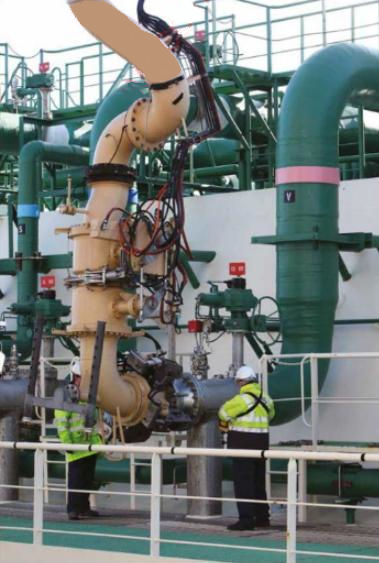
Loading arm connection and manifold purging
When Equipment and cargo system of LNG onshore terminalsconnection of the MLAs is complete, they are purged and pressurised with N2 that is supplied by the terminal.
Typically, a pressure of 5 bar is raised in each arm. The responsible ship’s officer checks all associated joints for leakage. Soapy water is still the preferred means of leak detection.
The procedure for purging will vary Terminal Operations for LNG or LPG Carrier after Arriving in Portfrom terminal to terminal but will include the following stages:
- after connecting the MLA, the manifold will be pressurised to the maximum allowable pressure at the manifold for approximately 5 minutes to check for leaks. This will be as agreed between the ship and the terminal at the pre-discharge meeting;
- purge MLAs until a reading of < 1 % O2 is achieved on the oxygen meter.
The reading on all meters should be witnessed to the satisfaction of both ship staff and shore personnel before proceeding on to the next operation. When terminal meters are used, a comparison with the ship’s should verify the accuracy of the shore instruments.
Once the integrity of the MLAs has been confirmed, they are depressurised in a controlled manner. While depressurising, the gas is checked using a portable O2 meter, where a reading of < 1 % O2 is the typical requirement.
Dryness of the gas is also an important issue and can be part of the standard checks at some terminals. Lower than minus 50 °C (-50 °C) is the usual requirement. This humidity test is important and reflects the dryness of the terminal’s installation. If there has been maintenance at the terminal moisture may have entered the shore pipelines. This could cause icing at the manifold strainer (filters) when loading is underway, i. e. at a point of flow turbulence. This, in turn, may result in an unacceptable pressure differential developing across the manifold strainer.
Read also: Ship-to-ship LNG transfer operations
On completion of cargo operations, the MLAs will be drained by pressurising lines from the shore with N2. The spray line is used to allow for efficient draining of the MLAs. Remaining liquid in the manifold is released to the cargo tanks via the spray line. This will be carried out in coordination with the terminal. The process may be repeated several times to ensure complete drainage.
After draining has been completed, the arms and manifold will be purged with N2 until a reading of < 1 % hydrocarbon is achieved.
When purging the vapour manifold, it is essential that the vapour crossover block valve is fully open. Again, meter readings will be witnessed both by ship and shore staff.
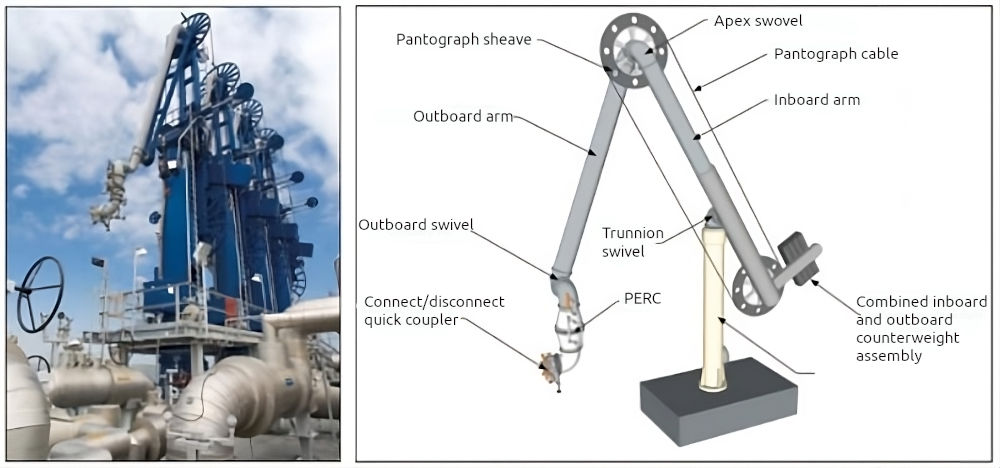
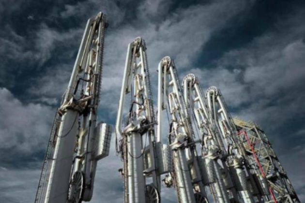
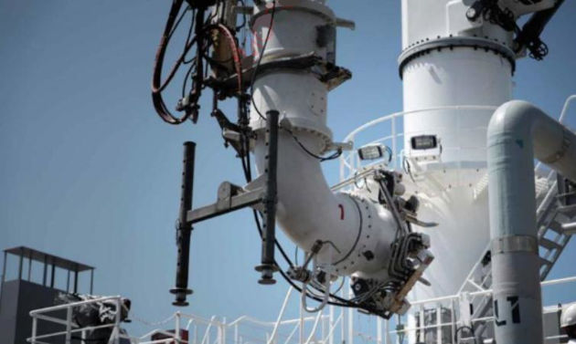
Marine loading arms
There are two main types of marine loading arm (MLA) used for LNGCs:
- rotary and;
- double counterweight arms.
Details of both arm types are given below. Both of these arms have maintenance advantages because of their simplistic drive systems. They can be laid over on their backs for maintenance accessibility.
Any disadvantages in operating are due to the requirement to manhandle, especially for the larger sizes and the cryogenic nature of the product.
Note, MLAs may also be referred to as:
- loading arms;
- chicksans;
- hard arms.
Purpose of safety devices
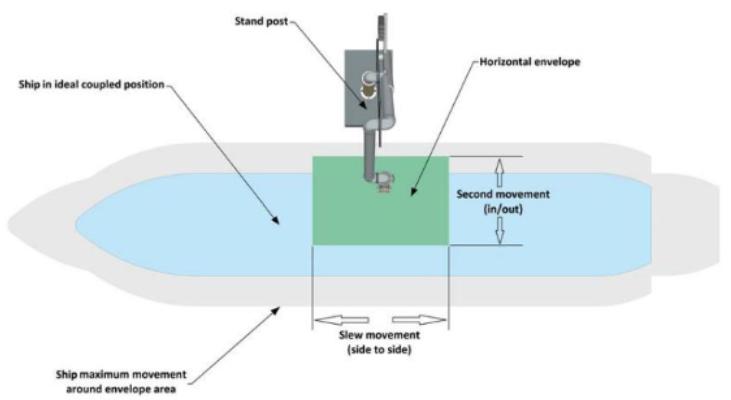
MLA operating range
The range is determined by the ship’s flange position and freeboard, the jetty, tides and allowable drift data. From this information, an operating envelope diagram is generated.
The rotary counterweight marine arm (RCMA) “S” maintains the LNG product carrying line separately from the mechanical structure, with only a single counterweight system used to balance the inboard and outboard sections of the arm.
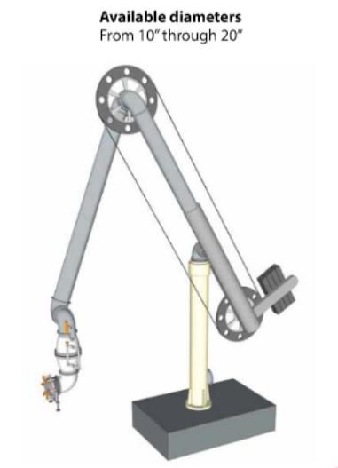
This arm is fully balanced in all positions. Two independent counterweight systems are used to balance the inboard and outboard sections of the arm.
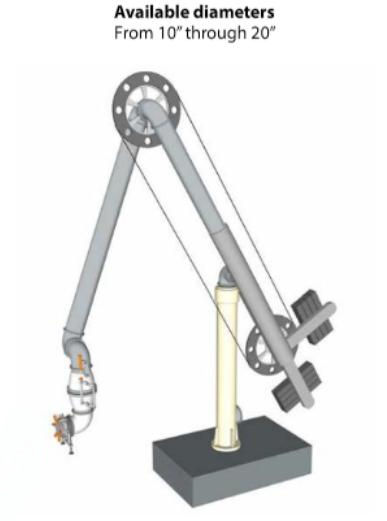
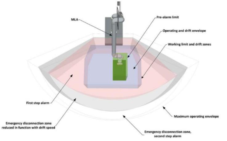
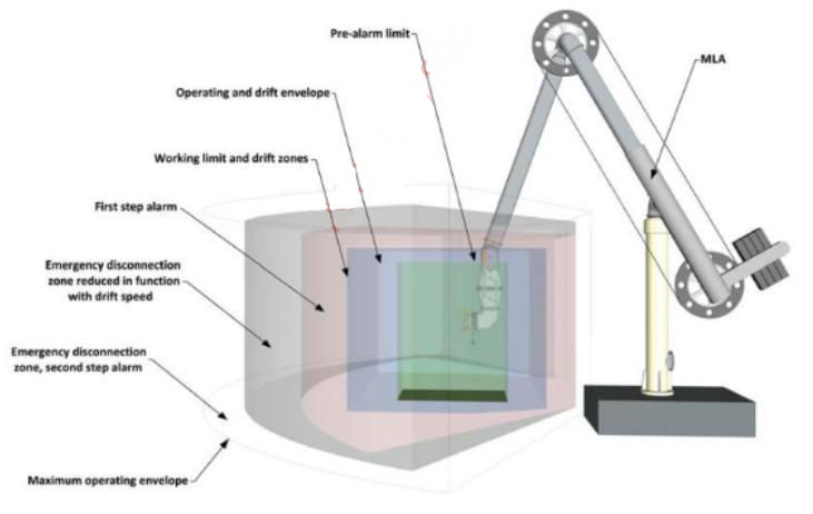
The arms are sized to reach all areas of the operating envelope. The arm operating parameters, (see Figures 7-8) set in most cases by limits of stress in the arm or ship’s manifold, are typically:
- 150° maximum apex angle;
- 15° maximum outer arm tuckback from vertical;
- 10° maximum outer arm elevation above horizontal;
- +45° maximum slew or luff angle.
The stresses referred to are produced by the fluid load and the relative movement of the ship.
The arm is normally protected from exceeding its limits by visual indicators or electric audible/visual alarms that monitor the angles during connection/disconnection and loading cycles.
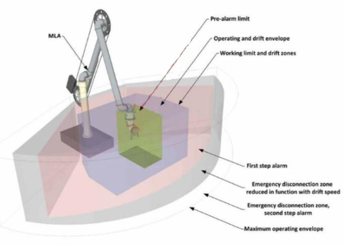
The ship’s manifold is only partly protected by these alarms. There are areas where overstress can occur that are outside the operating envelope but still inside the alarm envelope. Specific systems have been developed for protection in these areas.
Some manifold protection can be gained from the use of support jacks. These can be either front mounted, for greatest load carrying, or rear mounted for best practical positioning (clear of drip tray).
MLA handling procedures
General manoeuvring characteristics vary considerably between different types of MLA and this must be given adequate consideration during operator training and work scheduling at terminals.
The following points should be taken into account:
- only one MLA should be capable of operation at a time;
- there should be a central control panel on the jetty that has a good view of all MLAs through all positions, from stowed to the LNGC’s manifold;
- manual hydraulic controls are the most reliable as some speed throttling (or “feel”) is obtained;
- one portable/remote control should be available for use;
- electric controls are usually low current, intrinsically safe systems as it is dangerous to have higher voltage lines in the vicinity of MLAs. However, a hydraulic, manual control backup must be retained.
Best practice when operating MLAs:
- check overreach alarms prior to the arrival of the LNGC;
- operate all arms and control systems at least weekly;
- before locking arms, ensure they are completely drained;
- ensure that speed controls are as per the manufacturers recommendations;
- if jacks are fitted, use them at every loading and not only when they are necessary;
- ensure that the storm lock remains in an open position during the loading cycle;
- at the end of loading, drain the arms fully and purge with N2.
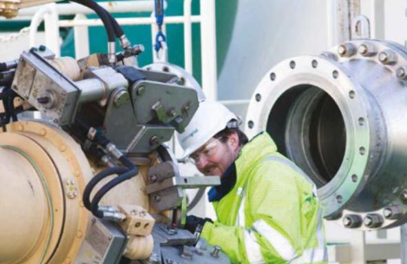
Emergency breakout operation
The emergency release system (ERS) consists of a double ball valve fitted with an emergency release coupling (ERC). This is also referred to as the dry break connection. On activation, this leaves one valve connected to the ship’s manifold and, as a result of the severing of the connection causes the “tail” of the MLA to become heavier with gravity, providing a natural lift off (normally simultaneously), that has no reliance on complex sequencing or drives.
The ERS:
- should be hydrostatically tested to 1,5 × its design pressure before coming in to service;
- consists of an ERC that is situated between two cargo valves and located in the vertical leg of the triple swivel assembly;
- will initiate a clean break of the MLA from the LNGCs manifold;
- should, in the event of the loss of hydraulic or electrical power, remain “as is” and completely closed;
- can be activated:
- automatically, when the arm reaches a specific limit;
- manually using a push button;
- manually, using hydraulic valves.
The ERC cannot operate before the cargo valves are closed. A method should be provided for the ERS to be tested without releasing the ERC.
The volume of cargo between the valves should be minimised to reduce any spillage. During cargo operations, ship’s personnel must be aware of operating criteria of MLAs.
Note: if the MLA disconnects, it will delay the operation.
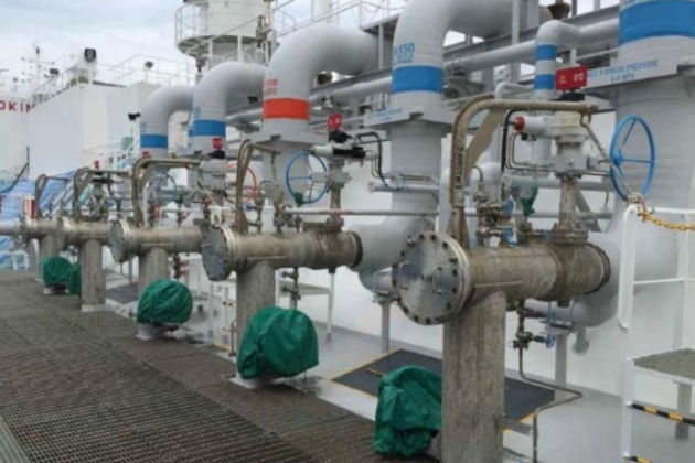
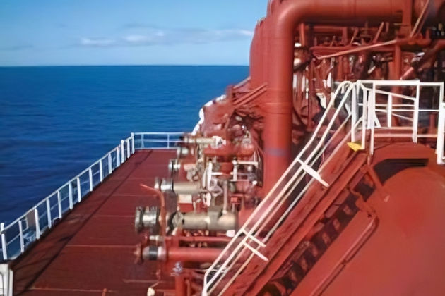
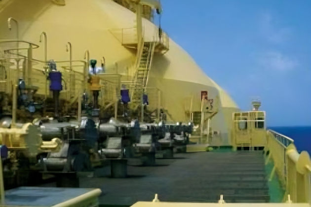
Manifold equipment
The following associated/related equipment will be in the vicinity of the manifold:
- eight manifold strainers with a mesh size of typically ASTM 60, four for loading and four for discharging. In some cases, four bi-directional strainers would replace eight individual manifold strainers. The presence of water or other contaminants in the cargo system can be eliminated by taking care during refit and maintenance operations and through strict adherence to inerting and purging procedures. However, certain ports may not allow the fitting of manifold filters. Strainers should be provided in accordance with the SIGTTO “Recommendations for Liquefied Gas Carrier Manifolds”. This SIGTTO document combines the manifold arrangements and cargo strainer guidelines for LNGCs;
- cargo reducers are not required but adapters should be provided that are suitable for connecting MLAs with hydraulically operated quick connect/disconnect couplers;
- a portable nozzle for emergency cargo jettisoning should be supplied and stored in way of the manifolds. The nozzle shall be capable of mounting on any liquid manifold, which extends 3 m over the ship’s side and provides an outlet velocity of 40 m/s when supplied by two cargo pumps operating at rated capacity;
- usually, four short distance pieces (SDPs), 16″ diameter, are available on LNGCs.
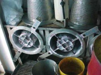
Methods for checks
Cargo tank contamination after post refit/repair can only occur by one of two means, namely:
- contamination taken on board during the loading process, i. e. across the manifold from the terminal. This is prevented by in-line loading filters fitted in the ship’s manifold, typically a size 60 mesh. Pressure differential across the manifold filters is a parameter that should be monitored on board during the loading process. Remember that it may be ice formation rather than debris that causes a partial blockage;
- contamination from the ship, usually as a result of equipment/material failure, i. e. Teflon valve seat, corrosion, etc. During discharge, 60 mesh discharge filters are fitted in the ship’s manifold so that any debris is contained and is not passed on to the LNG import terminal.
After each load or discharge (and warm-up), the appropriate filters should always be inspected and, if any debris is recovered, investigation should be taken to determine its origin.
Note: any debris discovered should be retained and any debris/discolouration of the strainer should be reported to the LNGC’s managers and investigated to determine the origin of the material.
Fitting procedures
The discharge/loading filters are always carried by the ship and fitted as part of the pre-port preparations. The filters are conical, flanged and fitted behind the manifold presentation bobbin. Unless bi-directional filters are fitted the filters only permit flow in one direction, so correct fitting for the appropriate operation is essential. Every time the filters are fitted, they should be thoroughly cleaned and carefully checked to ensure their construction remains sound.

- The international group of liquefied natural gas importers (GIIGNL). LNG custody transfer handbook / 6th Edition: 2020-2021.
- ©Witherby Publishing Group Ltd. LNG Shipping Knowledge / 3rd Edition: 2008-2020.
- CBS Publishers & Distributors Pvt Ltd. Design of LPG and LNG Jetties with Navigation and Risk Analysis / 4th Edition.
- NATURAL GAS PROCESSING & ITS ENERGY TRANSITION ROLE: LNG, CNG, LPG & NGL Paperback – Large Print, November 14, 2023.
- OCIMF, ICS, SIGTTO & CDI. Ship to Ship Transfer Guide for Petroleum, Chemicals and Liquefied Gases / 1st Edition, 2013.
- The Society of International Gas Tanker and Terminal Operators (SIGTTO). Ship/Shore Interface / 1st Edition, 2018.