The LNG systems represent a marvel of modern engineering, designed to liquefy, store and regasify natural gas at cryogenic temperatures. LNG systems characteristics include specialized materials capable of withstanding extreme cold, sophisticated insulation techniques and precise temperature control mechanisms that maintain gas in its liquid state. The core components of LNG systems work in harmony to achieve maximum energy density while minimizing the storage footprint compared to conventional gas storage methods.
- Emergency Shut-Down System
- Emergency Shutdown System Principle
- Main Feature
- Remote Sounding System and Very High Level Alarm System
- Remote Sounding System
- Independent Very High Level Alarm System
- Boil-off Control System
- General Description
- Boil-off Control System
- Vent Mast Control
- Boil-off Gas Heaters
- Forcing Vaporizer
- Low Duty Compressor Control
- Boil-off in Engine Room
Operational controls within the LNG systems ensure safe and efficient performance throughout all processing stages. The LNG systems incorporate multiple layers of automation, including pressure regulation, leak detection and emergency shutdown capabilities that respond to deviations from normal parameters. Modern LNG systems design feature integrated control architecture with redundant safety protocols and real-time monitoring that provide operators with comprehensive oversight of all critical functions and parameters.
Emergency Shut-Down System
Emergency Shutdown System Principle
In the event of fire or other emergency condition, the entire Cargo System – Tank Constructioncargo system, gas compressors and master boil-off gas isolating valve to the engine room may be shut down by a single control.
Shut down of the cargo system is actuated either manually or automatically by fire or certain off limit conditions.
Main Feature
The manual emergency controls are located in the following locations:
- CACC.
- Wheelhouse.
- Fire control station.
- Each tank liquid dome (4 units, one at each dome).
- Forward area.
- Cargo machinery motor room.
- Cargo machinery room.
- Port and starboard manifold platforms (one each side).
Automatic shutdown for fire is controlled by nine fusible plugs located as follows:
- Each tank liquid dome (four units, one at each dome).
- Cargo machinery motor room (one unit).
- Cargo machinery room (two units).
- Port and starboard manifold platforms (one each side).
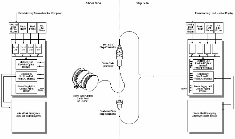
There are three ESDS interface connections made to the shore facility, i. e., electrical, visual and pneumatic. In port, the visual link and pneumatic systems will inform the shore of any ship’s ESDS actuation and will stop the loading or discharge pumps and close the shore liquid valves. The electrical link is mainly for redundancy back-up (see Figure 1).
Automatic shutdown occurs when any of the following conditions occurs:
- Vapor header pressure falls to within 0,3 kPa of atmospheric pressure.
- Vapor header pressure falls to primary insulation space header pressure.
- Each tank pressure falls to within 0,5 kPa of the insulation barrier space pressure.
- Each tank pressure falls to the insulation space pressure.
- Very high liquid level (99 %) in any tank.
- Automatic shutdown for fire.
- Shutdown signal from the terminal.
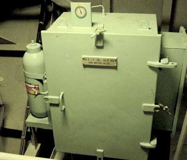
Initiation of an ESDS signal will operate solenoid valves ESDS (see Figure 2), thereby porting hydraulic oil onto the ESDS valves.
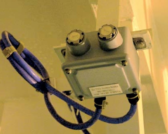
Accumulators are fitted to each ESDS section so that in the event of a power pack failure it is still possible to shut the valves. The cargo pumps including the stripping/spray pumps are shut down. The fusible plugs are fitted into the pneumatic control air line, whereby on melting, the pressure drop on the control is detected, which has a five second time delay before a signal is sent to Emergency Shutdown System (ESDS) on Liquefied Gas Carriersthe ESDS system. The fusible plug is designed to melt at between 98-104 °C (see Figure 3).
Remote Sounding System and Very High Level Alarm System
Remote Sounding System
The following is the description of a typical remote sounding system (see Figure 4).
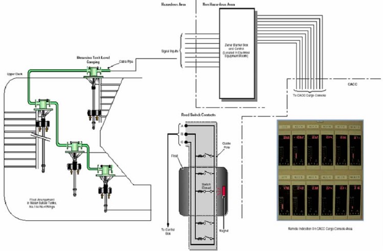
It is a float type gauging system incorporating a high-level alarm operating at 95 % of tank capacity. The alarms are indicated at the cargo control console and both digital and analogue gauging outputs are available.
The level master detector at the top of the tank outputs its signal to Zener barriers, which act as the interface between the hazardous area and the non-hazardous area. From the barriers, the signal goes to the control box in the electrical equipment room for interpretation and forwarding to the various display units.
The bottom 200 mm of the tank depth cannot be measured with this system, and manual gauging must be used to verify that the tank is empty after discharge.
Remote sounding of the ship’s ballast, FW, FO, LO, atmospheric drain and relevant bilge holding tanks, is via the Masasino system of magnetic floats rising and falling up a support column. The column has a series of reed switches and resistors arranged as a potentiometer at intervals of 2 cm. As a float magnet rises up the column, the reed switches adjacent to the float connect the center connection to the resistor chain. The level can therefore be determined by the voltage from the center connection with respect to the common connection of the element. Head mounted electronics convert the voltage from the potentiometer into a 4 to 20 mA signal, which is transmitted to a control box in the electric equipment room.
The eight ballast tanks and forward HFO storage tanks are located in a hazardous area. The signal from these tanks is led to the control box in the electric equipment room via Zener barriers.
The ballast system tank signals are transmitted to the cargo I/O cabinet, with an analogue and digital display on the CACC cargo console. The remaining tank soundings are led to the machinery I/O cabinet. Only the main turbine LO sump indication has an analogue and digital display on the CACC machinery console.
Independent Very High Level Alarm System
Two very high level alarms per tank are provided by independent point sensing elements. Fixed sensors inside Independent Cargo Tanksthe cargo tanks detect the cargo at predetermined levels and system accuracy is ± 6 mm.
The very high alarm adjusted at 98,6 % of the tank height when activated, will close the corresponding tank filling valve.
The very, very high alarm adjusted at 99 % of the tank height when activated, will initiate an Emergency Shut Down alarm (ESD).
This involves the shutting of the manifold and tank-loading valve of the tank in question. The IAS has facilities to inhibit at 98,6 % and 99 % to allow opening of the tank valve during the level alarm testing.
In addition, a blocking function is provided to allow all cargo tank level alarms to be overridden when at sea.
Boil-off Control System
General Description
The cargo tank boil-off must be removed in order to maintain equilibrium within the tanks at the designed operating pressure. The volume of boil-off is also increased on passage due to the energy dissipated by the agitation of the cargo caused by the motion of the ship.
Gas normally taken from the main gas header, is compressed using the low duty compressor(s) and is then heated in the fuel gas heater before being delivered to the boilers.
Boil-off Control System
The BOG control system is integrated into the IAS system. The system monitors the vapor header pressure in absolute and gauge mode.
The operator must first select the correct voyage mode in, which the controllers should operate on the IAS.
In this manner the sensors will collect and calculate the appropriate data for the controllers to operate.
The function of the sensors is to give the following signals:
- Available gas flow from cargo tank, for the control of the forcing vaporizer flow control.
- Excess BOG dump signal for the boiler steam dump control.
- Set point and process value for the vent mast control.
Vent Mast Control
Vent mast valve is controlled from the IAS and has three control levels as follows:
- Cargo tank protection.
- Manual vent inhibit.
- Vent control at Vent Mode.
In the cargo tank protection mode, the vent mast valve will open to full flow (100 % capacity) when a pressure on the vapor header exceeds the set value PVH1. The valve will stay in this mode until the pressure registered on the vapor header drops below PVH2, at, which point the valve will close.
In the cargo tank protection mode, the manual vent-inhibit and vent-control at vent mode is disabled and manual operation of the vent valve is not available. In the manual vent inhibit mode, the vent valve will stay closed while the engine telegraph is in astern or, if in the wheelhouse, the vent inhibit order is in operation. In this mode the manual operation of the vent mast valve is not available. The cargo tank protection mode will override the manual vent inhibit.
In the vent mode, the IAS controls the opening of the vent mast valve according to the vapor header pressure, while BOG is being routed to the engine room for burning in the boilers. In this mode the manual operation of the vent mast valve is not available.
Boil-off Gas Heaters
Via the IAS, the outlet temperature of the BOG through the boil-off heaters is monitored, with the temperature at the outlet from the heater being regulated by the activation of the heater inlet valve and heater bypass valve.
Manual operation of the control valves is not available while control is from the IAS, although the manual operation of the output of the PID controller is available.
Under boil-off heater trip conditions the IAS will automatically close the heater inlet valve and open the bypass valve. Both valves will be locked in this mode until the trip condition is recovered. The boiler controller will receive a signal from the IAS of the heater trip and order a changeover to FO burning only.
Forcing Vaporizer
The IAS monitors the BOG flow rate and outlet temperature from the forcing vaporizer and sets the control valves on the forcing vaporizer accordingly.
There are three modes at, which the forcing vaporizer is operated:
- Manual mode.
- Sequence manual mode.
- Sequence cascade mode.
In manual mode, the control parameters are set locally by the operator for BOG flow and temperature.
In sequence manual mode no manual operation of the flow control valve is allowed. Output is equalized to a setting of the preset value of flow control valve opening as previously defined. In this mode it is possible to transfer to the manual operator mode.
The sequence cascade mode does not allow any intervention by the operator apart from being able to select a mode transfer. In this mode, the demand from the boiler and the cargo tank pressure are matched automatically.
Low Duty Compressor Control
The LD compressors receive a control signal corresponding to the fuel gas control valve position and the vapor header pressure, which acts upon the inlet vain guides position and regulates the output from the low duty compressor accordingly in order to give the optimum output as demanded.
Boil-off in Engine Room
The only communication that is permitted between the cargo area and the engine room is through the boil-off line. Of course, the presence of boil-off in the engine space is a source of hazard and therefore The Origins of the IGC Codethe IGC Code contemplates specific precaution for handling the boil-off in the engine room. Two arrangements are contemplated:
1) FIRST OPTION
The boil-off pipe is to be contained in another pipe for all the length of its running inside the engine room. The concentric space between the pipes is pressurized by inert gas at a pressure greater then the pressure of the boil-off. Where this option is adopted, the pressure in the space between the pipes is continuously monitored. In the case the pressure of the inert gas equalize the pressure of the boil-off an alarm and the following automatic operations are activated:
- The master valve situated at the entrance of the boil off line in the engine room and the other automatic valves in line (at least two in series) shut.
- A further automatic valve, interlocked to the automatic valves of the line opens to vent the portion of the boil-off line that remains isolated.
- Once vented the inside of the gas fuel system between the master valve and the burner or engine is purged with inert gas.
2) SECOND OPTION
The boil-off pipe is installed in a duct. The duct is air ventilated with at least 30 air changes per hour whenever boil-off is present in the pipe. The pressure in the duct is kept below the atmospheric pressure. Continuous gas detection is provided in the duct. The master gas valve shut down if gas is detected in the trunk and/or if the required flow of air is not achieved.

- The Society of International Gas Tanker and Terminal Operators (SIGTTO). Liquefied Gas Handling Principles on Ships and in Terminals (LGHP4) / 4th Edition: 2021.
- The international group of liquefied natural gas importers (GIIGNL). LNG custody transfer handbook / 6th Edition: 2020-2021.
- American Gas Association, Gas Supply Review, 5 (February 1977).
- ©Witherby Publishing Group Ltd. LNG Shipping Knowledge / 3rd Edition: 2008-2020.
- CBS Publishers & Distributors Pvt Ltd. Design of LPG and LNG Jetties with Navigation and Risk Analysis / 4th Edition.
- NATURAL GAS PROCESSING & ITS ENERGY TRANSITION ROLE: LNG, CNG, LPG & NGL Paperback – Large Print, November 14, 2023.
- American Gas Association, Gas Supply Review, 5 (February 1977).
- The Society of International Gas Tanker and Terminal Operators (SIGTTO). Ship/Shore Interface / 1st Edition, 2018.
- Department of Transportation, US Coast Guard, Liquefied Natural Gas, Views and Practices Policy and Safety, p. IV-3.
- Department of Transportation, US Coast Guard, Liquefied Natural Gas, Views and Practices Policy and Safety, p. IV-4.
- Federal Power commission, Trunkline LNG Company et al., Opinion No. 796-A, Docket No s. CP74-138-140 (Washington, D. C.: Federal Power Commission, June 30, 1977).
- Federal Power Commission, Final Environmental Impact Statement Calcasieu LNG Project Trunkline LNG Company Docket No. CP74-138 et al., (Washington, D. C.: Federal Power Commission, September 1976).
- Federal Power Commission, «FPC Judge Approves Importation of Indonesia LNG».
- OCIMF, ICS, SIGTTO & CDI. Ship to Ship Transfer Guide for Petroleum, Chemicals and Liquefied Gases / 1st Edition, 2013.
- Federal Power Commission, «Table of LNG imports and exports for 1976», News Release, June 3, 1977, and Federal Energy Administration, Monthly Energy Review, March 1977.
- Office of Technology Assessment LNG panel meeting, Washington, D. C., June 23, 1977.
- Socio-Economic Systems, Inc., Environmental Impact Report for the Proposed Oxnard LNG Facilities, Safety, Appendix B (Los Angeles, Ca.: Socio-Economic Systems, 1976).
- «LNG Scorecard», Pipeline and Gas Journal 203 (June 1976): 20.
- Dean Hale, «Cold Winter Spurs LNG Activity»: 30.