This article covers basic information about Liquefied Petroleum Gas (LPG) Reliquefaction Plant, why reliquefaction are important, systems of reliquefaction, rules and requirements.
- Carriage of LPG by Sea
- Why is LPG reliquefaction required?
- Boiling point of LPG cargoes
- Standard configuration
- Insulation, boil–off and plant capacity
- System types and requirements
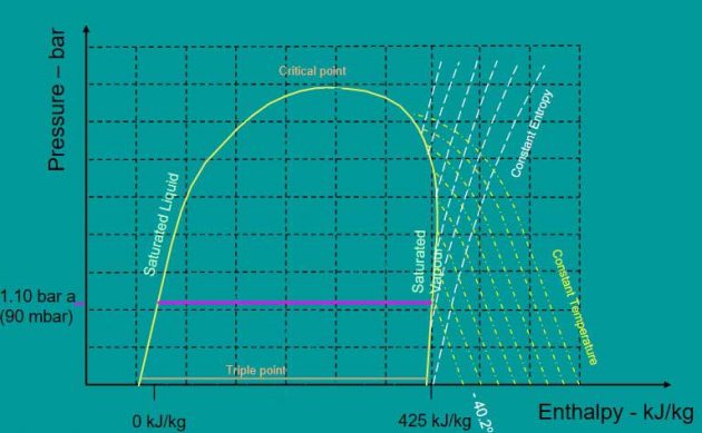
- Refrigeration reliquefaction & evaporation
- Reliquefaction plant capacity
- Reliquefaction systems
- Vertical cargo condenser
- Buckhardt (Sulzer) 2-cylinder oil-less compressor
- Lloyd’s Register design involvement, IGC Code and Rule requirements
- Conclusion
Carriage of LPG by Sea
- 1931 Agnita – build to carry petroleum in cylindrical tanks.
- 1934 Megara – Modified LR classed oil tanker carries LPG in small pressurised tanks.
- Late 1930’s to 1950’s – Gradual development, at first coastal USA, then international.
- 1959 – First semi-pressurised gas ship.
- 1961 – First fully refrigerated gas ship.
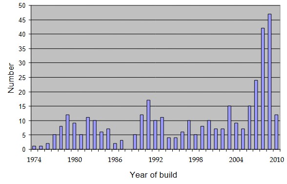
LPG Gas Ship over 10 000 gt – by year
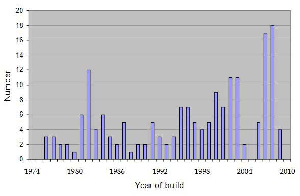
LPG Gas Ship between 5,000 and 10,000 gt
Why is LPG reliquefaction required?
Boiling point of LPG cargoes
Boiling point of various cargoes at atmospheric pressure:
- Propylene: -47,7 °C.
- Commercial propane (2,5 %): -45,2 °C.
- Propane: -42,1 °C.
- Ammonia (anhydrous): -33,3 °C.
- Vinyl chloride (VCM): -13,8 °C.
- iso-Butane: -11,7 °C.
- Butylenes: -6,3 °C.
- Butadiene: -4,4 °C.
- Butane: -0,6 °C.
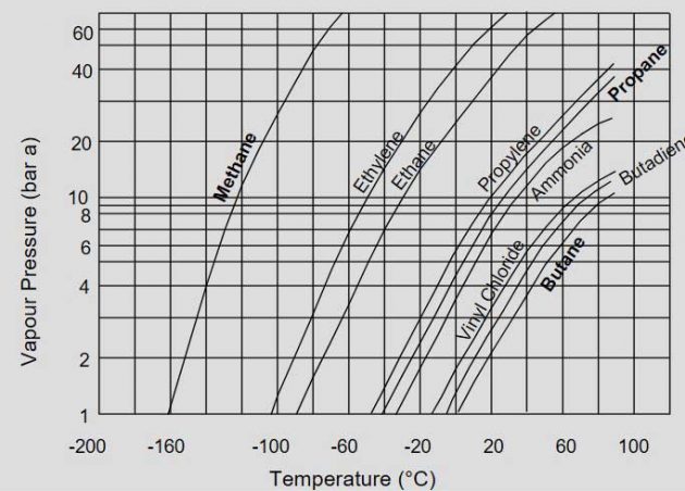
Saturation pressure temperature relationship
If left the cargo will equalise at the saturation pressure associated with the surrounding ambient temperatures.
As an example – take propane as the cargo:
| Boiling point | -42,1 °C | Pressure | 1,013 bar a |
| IGC Code sea water | 32 °C | Pressure | 11,3 bar a |
| IGC Code air | 45 °C | Pressure | 15,3 bar a |
| The International Maritime Dangerous Goods (IMDG) Code requires large (> 1,5 m dia) bare propane cylinders to be designed for: | |||
| IMDG Code | 60,5 °C | Pressure | 21,4 bar a |
Standard configuration
So what causes the pressure to increase in the cargo tanks?
During transportation:
- Heat ingress into the cargo tank through insulation.
- Mechanical energy due to liquid sloshing.
During loading:
- Heat ingress through tank walls/insulation.
- Heat from liquid headers, manifolds & loading arms.
- Heat energy from cargo tank and insulation.
Insulation, boil–off and plant capacity
LPG Carriage Conditions
Fully pressurised – 17,5 bar g (deck tanks):
- No boil-off, cargo at ambient temperature.
- Tank not fitted with insulation.
Semi-pressurised – ≅ 4,5 bar g:
- Restricted boil-off, cargo temperature controlled.
- Insulation & reliquefaction plant fitted – full or part duty.
Fully refrigerated – 0,25 bar g (at sea):
- Boil-off rate restricted by insulation.
- Cargoes at near ambient pressure.
- Reliquefaction plant capable of maintaining 2 cargoes.
Types of LPG insulation:
- Natural free flowing – boxed perlite.
- Natural blanket – Rockwool, glasswool for infill insulation.
- Man-made foam – polyurethane.

Heat transfer and boil-off rate
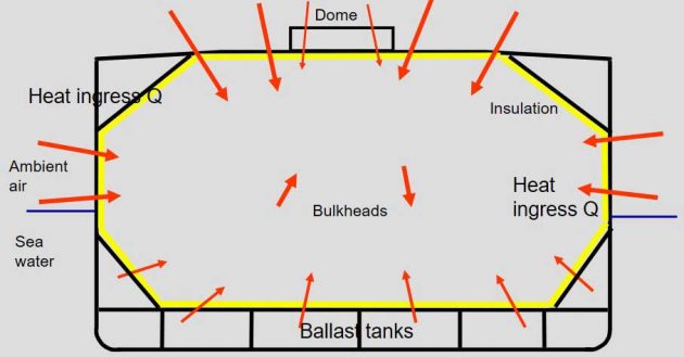
- Heat travels in one direction – hot to cold.
- Modes of heat transfer:
- Conduction – greatest effect.
- Convection – free convection most applicable.
- Radiation – extremely small, may be discounted.
- Cargo change of phase consideration – heat of vaporization (latent heat of evaporation).
- Effects of insulation thickness on boil-off rate.
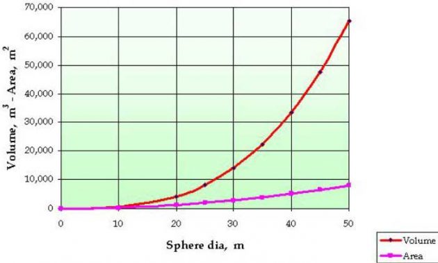
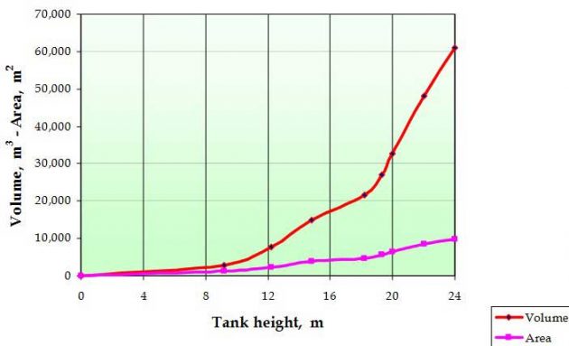
- Tank volume verses surface area relationship.
Reliquefaction plant capacity
Dependant on pressure temperature relationship:
- Fully Pressurised – Small Type C no plant.
- Semi-Pressurised – Type C but partly refrigerated.
- Fully Refrigerated – Near atmospheric (250 mbar) refrigerated and standby.
Reliquefaction plant utilising cascade system has duty split between reliquefaction and refrigeration circuits.
Current trend is to reliquefy the cargo boil-off gas in a cargo gas system – single or multi stage.
Type C tank volume limited due to scantlings.
| Cargo boil-off rate – input data | |||||
|---|---|---|---|---|---|
| Diagram of Aft LPG Cargo Tank – Layout & Areas | Area | Forward Section | Aft Section | ||
 | Deckhead | 424,65 | 347,44 | m2 | |
| Upper Hopper | 264,87 | 216,71 | m2 | ||
| Sides | 534,13 | 390,20 | m2 | ||
| Lower Hopper | 151,68 | 205,43 | m2 | ||
| Bottom | 563,99 | 393,59 | m2 | ||
| Bulkheads | 566,28 | 537,57 | m2 | ||
| Pump dome neck | 41,62 | m2 | |||
| Area – subtotal | 2 547,2 | 2 090,9 | m2 | ||
| Total area | 4 638,18 | m2 | |||
| Area less bottom | 3 431,78 | m2 | Projected | ||
| Cargo boil-off rate results | |||
|---|---|---|---|
| Results | |||
| Cargo Tank Details | |||
| Total volume of cargo tanks | 82 186 | m3 | |
| Total volume available for cargo at 98 % full | 80 543 | m3 | |
| Weight of cargo carried | 47 079 437 | kg | |
| Heat Leakage and Boil-Off Rates | |||
| Maximum heat flow – insulation layer only | 397 920 | W | |
| Boil-Off rate | 0,1673 | % | |
| Maximum heat flow – containment system | 390 085 | W | |
| Boil-Off rate | 0,1640 | % | |
System types and requirements
Refrigeration reliquefaction & evaporation
What is refrigeration?
“The process of taking heat energy from a place it is not wanted to a place where it’s dissipation does not matter” (not have an environmental effect)
What is reliquefaction?
“A process where the boil-off vapour is collected, recondensed and returned to the vessel as a liquid”.
Read also: Birth of the Reliquefaction, Design and Operation of the Reliquefaction LPG Plant
Evaporation – conversion of a liquid to vapour.
Evaporative cooling – reduction of heat energy which provides a cooling effect on remaining liquid.
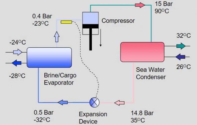
Reliquefaction plant capacity
Capacity to deal with heat input entering all of the cargo tanks during a loaded voyage:
- Have a reasonable margin in plant output over maximum load.
- Due regard to be given to additional capacity to deal with cargo loading conditions.
Suitable standby unit or an alternative means of controlling the cargo pressure/temperature.
Capability to be confirmed by testing. Special RMC (LG) notation will be assigned.
Reliquefaction systems
Classical cascade system – two stage by design:
- Refrigerant used in the initial stage.
- Cargo gas used in final stage.
Direct cycle – multi stage (up to 3):
- Number of stages dependant on cargo.
- Cargo gas used in each stage.
- Two or three cylinder compressors used.
Ethylene – separate refrigerant condenser.
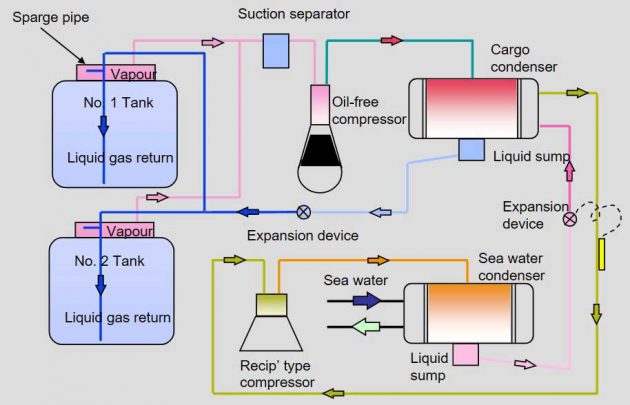
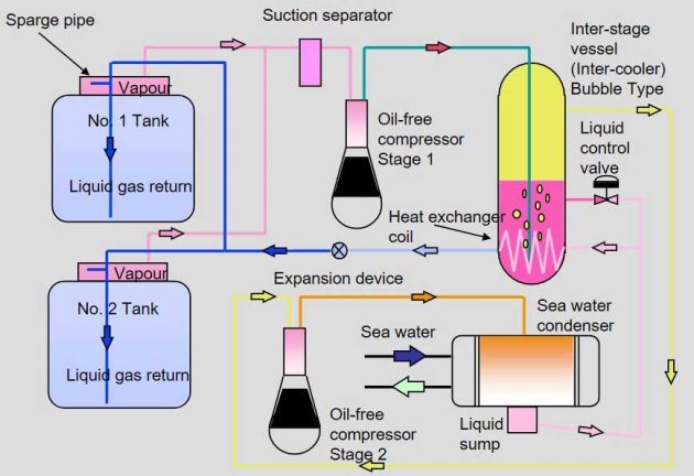
Ethylene & ethane reliquefaction systems
Cascade system for ethylene/ethane due to temperature:
- Cargo gas used in multi-stage system as normal.
- Refrigerant used in alternative condenser.
Compressor problems due to low suction temperature:
- Suction temperatures colder than -80 °C.
- Permanently heated cooling water circulated.
- Cylinder manufactured from graphite iron casting.
- Impact test requirements for materials.
Increase in flash gas at expansion device on return of condensate to the cargo tanks.
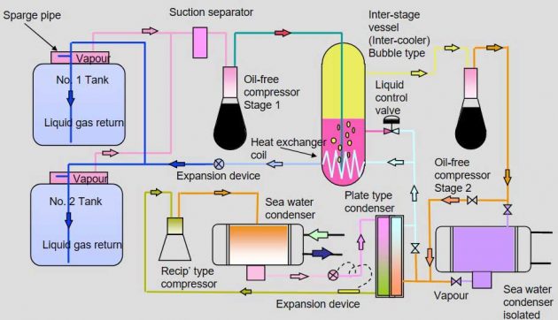
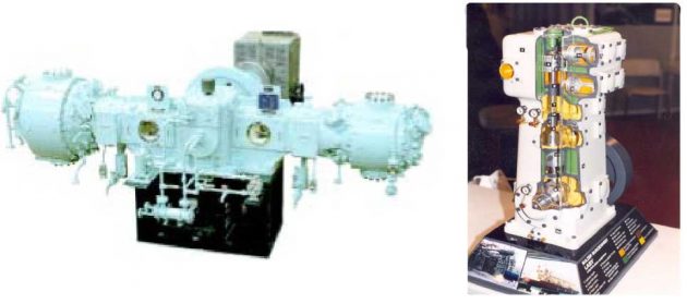
Reliquefaction compressors
- Suction Gas Engineering.
- Burckhardt (Sulzer).
- York Refrigeration (Sabroe).
- Grasso (Grenco Engineering).
| Compressor cargo requirements | |
|---|---|
| Discharge temperature set points – to stop polymerisation | |
| Butadiene | < 60 °C |
| Vinyl chloride (VCM) | < 90 °C |
| Other cargoes | 150/160 °C |
| Compressor suction pressure limits – to prevent dilution of oil | |
| Butadiene & vinyl chloride (VCM) | 0,5 bar g |
| Butane | 1,5 bar g |
| Other cargoes | 5,0 bar g |
| Butadiene to operate in single stage mode as possibility of condensate forming in the intermediate pressure system | |
Vertical cargo condenser
| Cargo compatibility | |||||||||||||||||
|---|---|---|---|---|---|---|---|---|---|---|---|---|---|---|---|---|---|
| Cargo | UN Number | Ammonia (anhydrous) | 1,3-butadiene | 1,3-Butadiene/Butane mixtures | Butane (iso and normal) | Butenes (Butylene) | Diethyl ether | Dimethylamine | Ethylamine | Isoprene | Isopropylamine | Propane | LPG (propane/butane mixtures) | Commercial propane – < 5% | Propylene | Vinyl chloride (VCM) | Vinyl ethyl ether |
| Ammonia (anhydrous) | 1005 | 0 | 0 | 0 | 0 | 0 | 0 | 0 | 0 | 0 | 0 | 0 | 0 | 0 | 0 | 0 | |
| 1,3-butadiene | 1010 | 1 | 0 | 0 | 0 | 1 | 0 | 1 | 0 | 0 | 0 | 0 | 0 | 0 | 0 | 0 | |
| 1,3-Butadiene/Butane mixtures | Mixture | 1 | 0 | 0 | 0 | 1 | 0 | 1 | 0 | 0 | 0 | 0 | 0 | 0 | 0 | 0 | |
| Butane (iso and normal) | 1011 | 0 | 0 | 0 | 0 | 0 | 0 | 0 | 0 | 0 | 0 | 0 | 0 | 0 | 0 | 0 | |
| Butenes (Butylene) | 1012 | 0 | 0 | 0 | 0 | 0 | 0 | 0 | 0 | 0 | 0 | 0 | 0 | 0 | 0 | 0 | |
| Diethyl ether | 1155 | 0 | 0 | 0 | 0 | 0 | 0 | 0 | 0 | 0 | 0 | 0 | 0 | 0 | 0 | 0 | |
| Dimethylamine | 1032 | 0 | 0 | 0 | 0 | 0 | 0 | 0 | 0 | 0 | 0 | 0 | 0 | 0 | 0 | 0 | |
| Ethylamine | 1036 | 0 | 0 | 0 | 0 | 0 | 0 | 0 | 0 | 0 | 0 | 0 | 0 | 0 | 0 | 0 | |
| Isoprene | 1218 | 0 | 0 | 0 | 0 | 0 | 0 | 0 | 0 | 0 | 0 | 0 | 0 | 0 | 0 | 0 | |
| Isopropylamine | 1221 | 0 | 0 | 0 | 0 | 0 | 0 | 0 | 0 | 0 | 0 | 0 | 0 | 0 | 0 | 0 | |
| Propane | 1978 | 0 | 0 | 0 | 0 | 0 | 0 | 0 | 0 | 0 | 0 | 0 | 0 | 0 | 0 | 0 | |
| LPG (propane/butane mixtures) | Mixtures | 0 | 0 | 0 | 0 | 0 | 0 | 0 | 0 | 0 | 0 | 0 | 0 | 0 | 0 | 0 | |
| Commercial propane – < 5 % | 1978 | 0 | 0 | 0 | 0 | 0 | 0 | 0 | 0 | 0 | 0 | 0 | 0 | 0 | 0 | 0 | |
| Propylene | 1077 | 0 | 0 | 0 | 0 | 0 | 0 | 0 | 0 | 0 | 0 | 0 | 0 | 0 | 0 | 0 | |
| Vinyl chloride (VCM) | 1086 | 0 | 0 | 0 | 0 | 0 | 0 | 0 | 0 | 0 | 0 | 0 | 0 | 0 | 0 | 0 | |
| Vinyl ethyl ether (stabilised) | 1302 | 0 | 0 | 0 | 0 | 0 | 0 | 0 | 0 | 0 | 0 | 0 | 0 | 0 | 0 | 0 | |
Buckhardt (Sulzer) 2-cylinder oil-less compressor
A further option – burning LPG
Chapter 16, paragraph 16.1.1 of the IGC Code states:
- Methane (LNG) is the only cargo whose vapour or boil-off gas may be utilized in machinery spaces of category A and in such spaces may be utilized only in boilers, inert gas generators, combustion engines and gas turbines.
The USCG Code of Federal Regulations (46 CFR 154.703):
- Methane (LNG) can be used in boilers, inert gas generators, and combustion engines in main propelling machinery space that use boil-off gas as fuel.
Burning LPG – can it be allowed?
IGC Code states that methane (LNG) is the only cargo whose vapour or boil-off gas may be utilized in machinery spaces of category A.
In accordance with SOLAS Chapter II-2, Regulation 3, paragraph 31.2, Machinery Spaces of Category A are:
- Which contain internal combustion machinery used for purposes other than main propulsion where such machinery has in the aggregate a total power output of not less than 375 kW.
For US controlled waters; guidance to be obtained from Commandant (G-MSO).
Burning LPG – current proposal
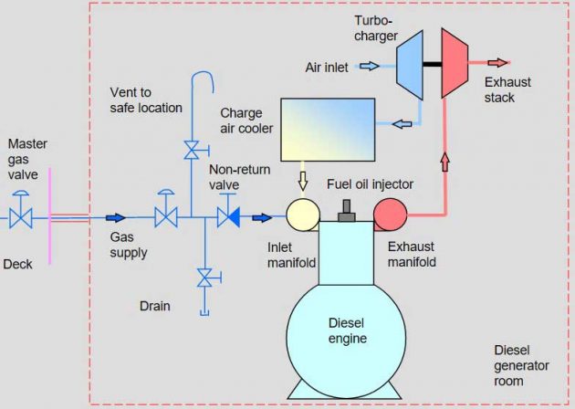
The use of LPG as a fuel in diesel generator engines has already been developed. In conjunction with MAN Diesel (Holeby), Lauritzen Kosan has installed such a system in a series of by LPG gas carriers built in Korea.
The LPG system is considered as an additional fuel:
- Used within a specific range and at the extremities of the engine’s maximum continuous rating (MCR).
- The LPG gas forms only a small proportion of the engine’s required fuel load.
- Currently only proposed to be used to allow “environmentally friendly” incineration of the remaining cargo when changing grades.
Lloyd’s Register design involvement, IGC Code and Rule requirements
Lloyd’s Register Rules and other requirements
- IGC Code – Chapter 7 LPG reliquefaction.
- Lloyd’s Register Rule requirements for reliquefaction plant – Part 6 Chapter 3.
- International Statutory Regulations applicable to all ship types, eg SOLAS, etc.
- USCG requirements for trading to USA Code of Federal Regulations, 46 CFR Section 154 refers.
- IGC Code – proposal being actioned through IACS and SIGTTO to force the IMO to update the current code.
Rules for Ships for Liquefied Gases and IGC Code
- Ship Arrangement.
- Cargo Tank Location.
- Ship Survival.
- Cargo Containment.
- Ship Structure.
- Materials & NDE.
- Fire Protection.
- Cargo Piping.
- Ventilation.
- Cargo Handling.
- Electrical.
- Instrumentation.
- Personnel/Operational.
- Cargo as Fuel (LPG?)
Survey Items – Gas Carriers
Refrigeration & Reliquefaction Plant:
- Cut-outs and safety stops.
- Control sequences – unloading gear.
- Tank temperatures & pressures.
Cargo Tanks and Void Spaces:
- Condition of insulation and vapour seals.
- Location and extent of cold spot or ice formations – done from void space.
Conclusion
Independent tanks, type A (MARVS < 0,7 bar)Type A LPG gas carriers will increase in size:
- Reliquefaction will continue.
- Volume of boil-off may require cascade systems to be used.
- Insulation thickness will remain at 120 mm.
Independent tanks, type C (MARVS < 0,7 bar)Type C gas carriers:
- Smaller “shuttle” tankers will still needed.
- Bi-lobe and cylindrical tanks used dependant on size.
Use of LPG as fuel – clarification at IGC Code update/rewrite:
- USCG may be a stumbling block.
