Learn how to optimize mooring procedures for LNG carriers with our comprehensive mooring management plan. Explore best practices for configuration, analysis, and operating limits to enhance safety and efficiency.
Our guide covers crucial aspects including mooring forces, wind and current considerations, and precautions for high-load conditions. Gain insights into quick release hook systems and remote release mechanisms for seamless emergency response.
Reference: SIGTTO “LNG Shipping Suggested Competency Standards”, Sections:
1 Have an awareness of the purpose and operating principles.
Mooring management
The terminal can use a number of principles of mooring management to reduce the possibility of ship break-away. These include:
- development of guidelines and a mooring layout for each Class of ship that is accepted at the berth. This forms the basis of the pre-berthing line layout studies that are made as part of the ship compatability study prior to acceptance by the terminal;
- ensuring that information concerning the ship’s mooring equipment is obtained prior to its arrival;
- examination of the ship’s mooring equipment to determine the modifications, if any, that must be made to standard guidelines;
- periodic inspection of line tending, or continuous measurement with tension monitoring equipment;
- the release of cargo transfer equipment (hoses/hard arms) and the arrangement for safe removal of the ship from the berth should the ship fail to take appropriate action/measures to ensure it is safely moored;
- ship/shore compatibility study prior to a first berthing at a terminal or where there are any mooring modifications.
Mooring configuration
Wire mooring lines or high modulus mooring ropes are used for LNGCs because they prevent excessive ship movement, which is the usual cause of damage to shore based loading arms. For safety reasons, it is common practice that mixed mooring lines should not be used.
Mooring lines are fitted with a length of synthetic rope on the shore end (mooring tails). The additional elongation of the mooring line system permitted by the tail reduces the risk potential associated with poor line tending, particularly in berths with large tidal variations and high loading/unloading rates. They are also valuable at berths having short breast or spring lines.
Mooring apparatus should be in compliance with the OCIMF publication “Mooring Equipment Guidelines” and with terminal requirements. The LNGC should have a mooring management plan in accordance with the above and any mooring analysis conducted.
Operating limits
Operating limits establish the environmental conditions within which the loading arms and other shore based equipment can operate.
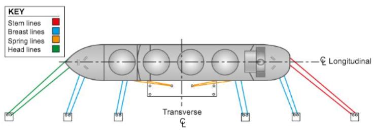
Should the wind, wave or current forces, either individually or combined, be excessive, the moorings run the risk of overload. If the LNGC’s movement is not controllable, the ship may be required to vacate the berth to avoid damage.
Mooring analysis
It is standard practice in the LNG shipping industry to conduct a full mooring analysis prior to an Ship/shore interface for safe loading and unloading of LNG/LPGLNGC’s visit to a terminal. This will take into account the physical characteristics of the ship and shore, including the location of mooring hooks, fairleads and winches, position of dolphins, fender characteristics and type of mooring lines available.
The environmental (metocean) conditions at the predicted time of arrival and for the duration of the LNGC’s stay at the berth are also considered, so the analysis is specific to each visit.
There are several commercially available software programs that can be used to conduct these analyses, which are computationally intensive, particularly when considering the dynamic forces involved.
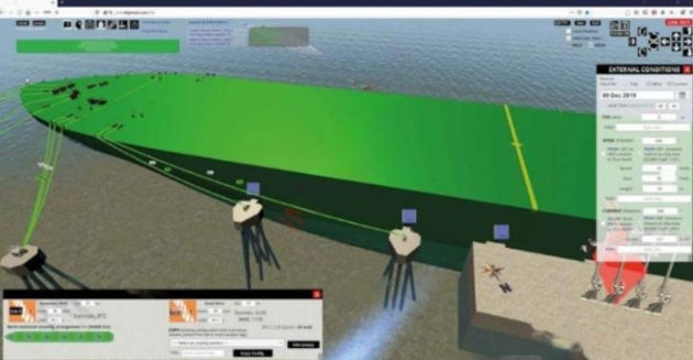
After inputting the mooring line arrangement that the LNGC proposes to use, programs will typically return a number of comprehensive reports. These detail the forces on the different mooring elements (mooring lines, winches, etc) in various situations, highlighting any mooring element submitted to forces exceeding the limits defined in “Mooring Equipment Guidelines” (OCIMF). This allows the ship and terminal to make any adjustments necessary to the planned mooring arrangement and to re-run the simulation to ensure that the new arrangements will result in safe working loads for all expected metocean conditions.
Mooring forces
A ship’s moorings must resist a large number of forces that are exerted on the ship, both environmental and operational. Failure of the moorings can result in damage to the ship, marine loading arms and the berth and lead to injury to personnel.
The problem to be solved when berthing is how to optimise the mooring arrangement to resist the applied forces. This problem can be solved by answering the following questions:
- What forces will the ship be subject to at this particular berth?
- What will be the effect of these forces on the mooring lines?
- What mooring arrangement is required to counteract these forces?
The forces acting on a moored LNGC are both environmental and operational. Environmental forces are caused by natural phenomena such as wind, waves, currents and tides. Operational forces include those caused by passing ships, changes in the trim, freeboard or draught and mooring line overtension.
Wind and current
In protected harbours the major source of environmental forces are the wind and current. Normally, in such areas ships are moored at conventional jetty facilities.
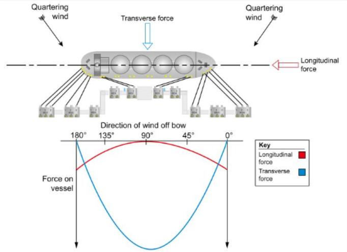
The magnitude of the wind force acting on a ship is influenced by the velocity of the wind and the area of the ship that is exposed to it. The force effect of the wind will double as the exposed ship area doubles, so the ship is least susceptible to wind forces when it heads into the wind and is low in the water, such as when fully laden.

Figure 5 demonstrates how the wind force acting on an LNGC varies with wind velocity and direction. For simplicity, wind forces on a tanker can be broken down into two components:
- a longitudinal force acting parallel to the longitudinal axis of the tanker;
- a transverse force acting perpendicular to the longitudinal axis.
The magnitude of wind force effect on the ship is related to the square of the velocity. If the wind velocity doubles, the force due to wind will be four times greater. If the velocity triples, the wind force will be nine times greater.
Water current force considerations are similar to those of wind force. The magnitude of current forces on a ship depend on the velocity of the current, the hull area exposed to the current and the underkeel clearance of the ship.
As with wind forces, current forces are directly related to the area of the ship that is exposed to them, so the maximum force of the current will be experienced when the LNGC is in a loaded condition and the current is acting directly on the beam. Conversely, the force is minimised if it is light in the water and its bow is headed into the current.
As with wind forces, current force increases with the square of the current velocity. If the current velocity doubles, the current force is four times larger. If the velocity triples, the force is nine times larger.
High current velocities are not as evident to the ship’s personnel and only a review of the current information for the terminal is reliable. It should be noted that it is possible for the subsurface currents to have a different velocity and direction to surface currents, especially at terminals that are located offshore.
Waves
A major consideration for ships at exposed mooring locations is the effect of waves. In such areas, ships are generally moored at sea-islands, single point moorings (SPMS) or multiple buoy moorings (MBMs).
Wave direction and frequency (period) are two factors that influence the effect of waves on a moored ship. Whether the ship responds by surging, swaying or yawing will depend on whether the waves are striking the moored ship head-on, beam-on or quartering, the frequency of the waves and the manner in which it is moored.
Read also: Wave and Impact Loads in Design of Large and Conventional Liquefied Gas Carriers
Ships do not usually respond to a single wave but to a system of waves. It is the cumulative effect of each wave in the wave train that causes the ship to move. This behaviour is noticeable by observing the rise and fall of the mooring line catenaries at a sea-island as the ship moves.
Sometimes, in harbours, very long period waves that are very difficult to detect visually are present. These waves are known as seiches and are potentially dangerous because of their ability to disturb moored ships. They are capable of forcing a moored ship to move slowly in a cyclic manner, causing high mooring loads. Movements with periods of one to three minutes are very typical. This movement is best observed by noting the rise and fall of the mooring line catenaries. If a moored ship is responding in this manner, the amount of ship motion may be modified.
Precautions in high mooring load conditions
Overload of mooring lines is evidenced by either direct measurement, observation of the moorings by experienced personnel or by winch slippage. The foll owing precautions and actions are likely to apply:
- harden-up on the winch brakes. Do not release brakes (or slacken from the mooring bitts) and attempt to heave in;
- discontinue cargo operations;
- disconnect cargo transfer equipment;
- call crew, lineman, mooring boats, tugs and put ship’s engines on standby;
- run extra mooring if available.
Quick release hooks (QRH) and capstans
The QRH is the foundation of any hazardous jetty mooring system and is recommended by both SIGTTO and OCIMF. They are used at all major oil and gas marine facilities worldwide.
The QRH facilitates the safe release of the ship without the need to reduce tension in the mooring lines. QRHs are designed for either manual or remote release.
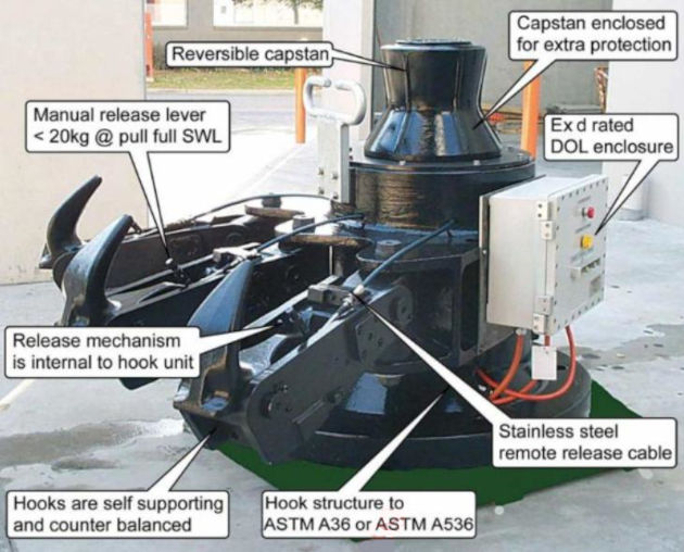
As only one mooring line should be placed on each QRH, enough hooks must be provided to allow this to be achieved. Each hook, whether a single hook or part of a multiple hook unit, should have a SWL of not less than the breaking strength of the strongest line (ship design MBL) anticipated for any ship visiting the berth. All hooks should be capable of being released separately and safely from the mooring point area, under any load condition.
The QRH facilitates safe release of the ship without the need to reduce tension in the mooring lines. QRHs are designed for either manual or remote release, from zero load up to the SWL capacity of each hook.
For LNG jetties, QRHs are usually in double, triple or quadruple configuration on a common support base. The base also incorporates a capstan that is used for hauling in each mooring rope to the hook, using a messenger line passed from the ship.
Ideally, the capstan motor should be positioned within the support base to improve protection from mechanical and environmental damage.
The units are designed to withstand static and dynamic forces exerted by the ship, often from wind or current load, while alongside. Hook configuration and capacity are determined by a mooring analysis. Hook SWL capacities for most terminals are now 150 tonnes SWL or above.
Pre-shipment testing of each hook is carried out, including proof load tests of up to 150 % of SWL and release test at SWL.
Remote release
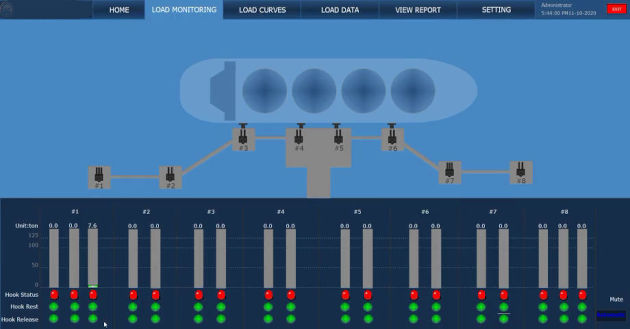
The release mechanism is integral to the hook. The purpose of the release mechanism is to release the mooring lines, which may be under tension, in a safe and controlled manner. Most manufacturers offer manual release at the hook using a removable lever. In addition, at most LNG facilities, a remote release system is installed. This provides the operator with the means to release every hook by electrical signal from a remote, safe location, via either a console or computer screen, as well as by push button at the hook unit itself.
Remote release systems for quick release hooks are installed for safety and productivity purposes.
When a ship is released from its moorings there is a significant increase in risk to personnel and, in particular, mooring crews in close proximity to lines that may be under tension.
During the release of a ship, as fewer and fewer lines are restraining its movement, additional load is placed on the remaining lines, increasing the probability of a failure. This is especially the case in bad weather, where the tugs often have difficulty restraining the ship’s movements.
The number of personnel required to release a ship can be minimised on facilities with remote release systems fitted. A senior shore operator would normally operate the system from the console and, although not mandatory, if hooks are within line of sight, other personnel may be positioned, forward and aft, to assist in the event of tangled ropes or local power failure.
If an emergency situation arose where a ship needed to be quickly released from its moorings a remote release system would provide a quick and safe method for a controlled release.
A risk assessment should be performed to assess risks to the ship from the line being released remotely. Before lines are released, the ship’s crew must be warned.
