This article discusses the safety of both the ship and the terminal during cargo transfer operations. All operations when o ship is alongside must be pre-planned and jointly managed in such a way that both the ship and the shore are aware of their responsibilities, capabilities and limitations. Throughout the cargo transfer operation, both ship and shore should work together according to mutually agreed procedures and responsibilities.
- Supervision and Control
- Design Considerations
- Jetty operations
- The terminal
- The ship
- Ship/Shore Compatibility Process (LNG)
- Ship and terminal particulars
- Mooring arrangements
- Ship manifold, shore hose and marine landing arm (MLA) characteristics
- Terminal gangway characteristics and ship deck loading configuration
- Ship/shore link (SSl)
- Other compatibility considerations
- Ship/Shore Compatibility Process (Other Liquefied Gases)
- Communications
- Prior to charter
- Prior to arrival
- Alongside the jetty
- Navigation docking, mooring, meteorological and oceanographic systems
- Discussions Prior to Cargo Transfer
- Ship/Shore Safety Checklist
- Supervision and Control During Cargo Transfer
- Joint agreement on readiness for cargo transfer operations
- Supervision
- Periodic checks during cargo transfer operations
- Operational Considerations
- Berthing and mooring
- Connection and disconnection of cargo hoses and MLAs
- Cargo handling procedures
- Cargo surveyors
- Gangways and ship security
- Bunkering
- Work permits
- Access to cargo manifold during transfer
- Fire-Fighting and Safety
- Linked Emergency Shutdown (ESD) Systems
- Terminal Booklet – Information and Regulation
- Training
Within the gas trade the ship/shore interface plays a vital part in operations. It is on area where differing standards and safety cultures may coexist. A central theme of this publication is to identify and close gaps in design standards and operational practices that may exist on either side of the interface so that ship and shore personnel can develop their procedures to suit the requirements of each party and by so doing it is hoped, improve their operational safety and reliability.
While this article is written to address the ship/shore interface, it is equally applicable to ship ship and ship/floating facility.
Supervision and Control
The jetty equipment relevant to the ship/shore interface includes:
- moorings;
- fenders;
- breasting/mooring dolphins;
- marine loading arms (MLAs) and hoses;
- ship/shore gangways;
- emergency shutdown arrangements;
- ship/shore communications links;
- fire-fighting equipment;
- operational equipment, ie vapour return, purging, cool-down etc.;
- security systems.
Liquefied gases are loaded and discharged at many terminals by a wide variety of ship types and sizes. Operations range from those required by very large self-contained liquefied natural gas (LNG) projects to those of smaller liquefied petroleum gas (LPG) terminals handling many different products.
For large LNG projects, dedicated ships may trade continuously between purpose built terminals for contract periods of up to 25 years or more and the loading terminal, the gas carriers and the receiving terminal, are designed as part of an integrated whole. Because the ships are designed to be compatible with the project terminal, personnel will be familiar with each other’s equipment and responsibilities. This model applies more to LNG export terminals than import facilities, which see a broader diversity of LNG ships. Some LPG projects, particularly those which involve long term contractual arrangements and the use of large ships and dedicated terminals, may have similar characteristics.
There are many LNG/LPG terminals that handle “spot” cargoes delivered by a very wide variety of ships and ship operators. Here, different gases are handled under a variety of conditions and LPG ships are frequently required to load more than one product simultaneously or to change cargoes on successive voyages.
In all gas trades it is considered essential, in the interest of safety and efficiency, that ship and terminal operators are:
- Familiar with the essential characteristics of ship and terminal cargo handling systems;
- aware of the division of responsibilities;
- able to communicate effectively during the port call.
These issues are discussed in more detail later in this article. A general discussion of these issues can also be Found in Part 4, Chapter 24 – “Precautions on Ship and Terminal during Cargo Transfer Operations” in the “International Safety Guide for Oil Tankers and Terminals (ISGOTT)” (Reference 2.4).
Design Considerations
Jetty operations
Because the ship/shore interface is the area where the activities of personnel on the ship and shore overlap during cargo handling, actions on one side of the interface will affect the other, so responsibility for safe operations does not stop at the cargo manifold for either ship or shore personnel. Responsibility for cargo handling operations is shared between the ship and the terminal and rests jointly with the ship’s Master and the responsible terminal representative. The manner in which the responsibility is shared should, therefore, be agreed between them to ensure that all aspects of the operations are covered.
From an operational viewpoint, it should be appreciated that at the ship/shore interface two differing cultures co-exist. To help ensure safe operations, a proper understanding of the working practices of both ship and shore personnel is necessary. Before and during operations, procedures of practical relevance have to be in place and jointly understood by both ship and shore personnel.
This is usually best achieved by properly addressing the ‘ship/ shore safety checklist’ (see point “Ship/Shore Safety Checklist” below), which should be supplemented by a suitable terminal operating manual, containing jetty information and regulations, which should be passed to the ship, preferably prior to arrival, to allow a thorough understanding by the ship’s staff.
There is a lot of variation in the design and operation of terminals and jetties and not all are dedicated solely to the handling of liquefied gases. The combined nature of the products handled can sometimes complicate operations. Variations in gas carrier and jetty construction can heighten the importance of safety issues at the interface, making them an important area requiring proper controls and good operational procedures.
LPG berths may have to handle ships of differing size and with a range of different cargo handling equipment. At LPG berths, local design variation at the ship/shore connection may result in the need to use either hoses or all-metal MLAs. The MLA may be hydraulically operated and/or it may be fitted with emergency release couplings (ERCs) and on emergency release system (ERS).
Liquefied gas cargo handling procedures may be complex and the cargo itself is potentially hazardous. A thorough understanding of ship and shore equipment and cargo properties is required. Good operating procedures and emergency plans should be in place.
The terminal
During the design of a new marine terminal, the minimum and maximum ship size that can be handled is established and the jetty and its equipment are designed with reference to it. Farther offshore, the port and berth approaches are surveyed. Once a terminal is ready for service the relevant information needed by visiting ships will be advised to the port authority, ships’ agents, pilots and ship operators. See also the SIGTTO–GIIGNL ship and terminal database (Reference 2.54).
If the jetty facilities are modified, for example to accept a different type of ship, then the same organisations should be advised. Simulator training involving local Harbour Pilots, Tug Captains and Masters of gas carriers likely to call at the terminal, may be considered for new and modified terminals.
It is good practice for terminals to audit their marine facilities from time to time and, in this respect, the publication “Marine Terminal Management and Self Assessment (MTMSA)” (Reference 2.55) can be of benefit.
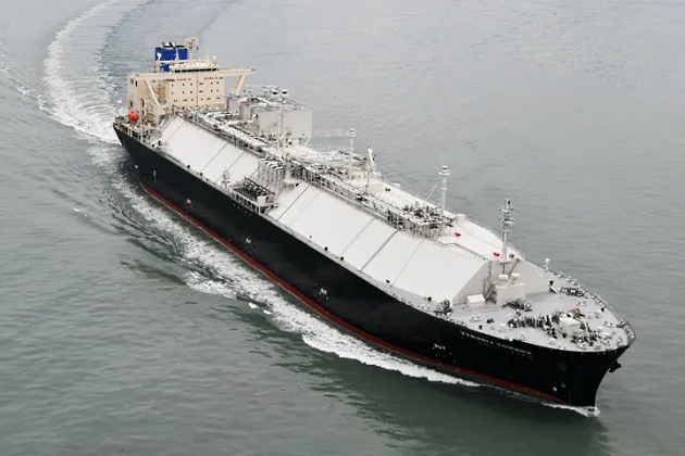
The ship
Gas carriers are usually built to ensure maximum compatibility with a wide range of terminals. This is assured, prior to construction, by the shipyard or the owner of the gas carrier.
Ship/Shore Compatibility Process (LNG)
The compatibility between any particular ship and terminal should always be confirmed, from a technical viewpoint, by terminal personnel and the ship’s operator/owner prior to acceptance of any nomination. Compatibility confirmation should include, as a minimum, the following:
- Ship and terminal particulars;
- mooring arrangements;
- ship manifold and MLA or flexible hose characteristics;
- terminal gangway characteristics and ship deck landing configuration;
- ship/shore link (SSL).
Reference 2.56 provides a template ship/shore compatibility questionnaire.
Ship and terminal particulars
To perform a compatibility study for ship and terminal particulars, the following documents, among others, may be referenced:
- ship capacity plan;
- ship general arrangement, including parallel midbody diagram;
- ship/shore interface plan;
- ship vessel particulars questionnaire (VPQ);
- marine terminal particulars questionnaire (MTPQ).
During the compatibility process, the review of the ship and terminal particulars should usually include the following questions:
- Will the ship’s draught meet the under keel clearance (UKC) limits for the waterway transit to the terminal and while the ship is alongside the terminal?
- Will the ship’s beam, length overall and air draught meet the requirements for the waterway transit and while the ship is alongside the terminal?
- Will the ship’s displacement be within the design limit for the terminal’s berth?
- Will the ship’s parallel midbody make satisfactory contact with the terminal fenders?
Mooring arrangements
To perform an accurate mooring analysis for a ship at a terminal, both the ship and terminal will need to provide specific information.
For the terminal, this information can usually be found in the following documents:
- Arrangement plan for the berth;
- fender plans, including reaction curves.
For the ship, this information can usually be found in the following documents:
- Vessel general arrangement;
- mooring arrangements and certificates;
- VPQ;
- trim and stability book.
The analysis of the mooring arrangement will usually include the following questions:
- Are mooring line loads and vertical angles within the acceptable range when the OCIMF criteria for winds and currents are simulated?
- If the mooring loads are not within the acceptable range when the OCIMF criteria for wind and currents are simulated, does the mooring arrangement provide adequate security and are adequate risk mitigations in place taking into account the terminal operating limits for wind and current, the availability of tugs and the terminal’s history regarding the prevailing metocean conditions?
- Are the terminal fenders and the ship’s hull loads within their design limits?
- Is the ship’s movement alongside the berth within the terminals limits for surge, sway, roll and vertical motions?
Ship manifold, shore hose and marine landing arm (MLA) characteristics

During the compatibility review process, analysis of the ship’s manifold and the MLAs or flexible hose connections will usually include the following questions:
- Are the terminal connections within the design limits for the ship’s maximum and minimum droughts, taking into account the extreme tides at the terminal and the expected ship motion?
- Is the ship’s manifold arrangement (spacing, setback, height above deck, drip troy) compatible?
- Do the ship manifold presentation flange surface finish and flange dimensions meet the MLA specifications?
- What type and mesh size strainers will be required?
- Do the ship’s handrails obstruct the connection of the MLAs?
- Which party will provide the manifold/hard arm gaskets if required?
- Any other terminal specific criteria to meet?
Terminal gangway characteristics and ship deck loading configuration
During the compatibility process a study of the terminal gangway and ship deck landing configuration will usually include the following questions:
- Is the terminal gangway within design limits for the ship’s maximum and minimum draughts, taking into account the extreme tides at the terminal and the expected ship motions?
- Does the ship’s deck configuration allow an unobstructed landing area within the gangway’s operating envelope?
- Does the gangway require special arrangements, such as removable handrails, reinforced support, special brackets or platforms?
Ship/shore link (SSl)
During the compatibility process a study of the SSL will usually include the following questions:
- Does the ship’s SSL match the terminal’s configuration for an electric, optical or pneumatic system?
- Does the link reach the connection point on the ship or terminal?
- Does the ship have the terminal file if mooring load information will be passed through the link?
Other compatibility considerations
Some terminals will require additional items to be addressed during the compatibility process, which may include but not be limited to the following:
- Does the ship have a connection plate that meets the terminal requirements for connecting the terminal’s bonding cable?
- Does the ship manifold hove utility (fuel oil, diesel oil or water) connections compatible with the terminal connections?
- Does the ship’s stores crane reach the terminal’s stores loading platform?
- Does the ship have a cargo surge relief system that meets the terminal requirements?
- What size manifold reducers does the ship hove available?
Ship/Shore Compatibility Process (Other Liquefied Gases)
Other liquefied gas cargoes hove, typically, been traded on a spot basis and the compatibility process is not as detailed as that for LNG terminals.

However, as a minimum, the following compatibility criteria will usually need to be confirmed:
- ship and terminal particulars;
- mooring arrangements;
- ship manifold and terminal hard arm or flexible hose characteristics;
- terminal gangway characteristics and ship deck landing configuration or, alternatively, the terminal landing area for the ship’s gangway;
- SSL (if available).
Communications
Communications should start before the intended voyage and continue until the arrival of the ship alongside, including the period of cargo operations and through until the ship departs. All communications should be carried out in an agreed common language and usually, apart from some coastal trades, this will be English.
Prior to charter
Prior to chartering a ship it is necessary for the parties concerned to exchange information to ensure a suitable match of ship and jetty. From a terminal’s viewpoint it is important for operations personnel to have a clear understanding of the restrictions, within the port and at the jetty, that influence the maximum or minimum size of ship they are able to receive. This information should be documented and made available to their commercial departments so that only ships having suitable dimensions and systems are received. SIGTTO, in cooperation with GIIGNL, provides on information portal strictly for its members, where owners/operators can upload terminal and ship information for general sharing with other members. While not a substitute for official commercial documentation, it provides a general source of information for the LNG industry.
Read also: Offshore terminal for transshipment of liquefied gas
To assist in determining the matching of ship and jetty mooring equipment, on receipt of the ship’s mooring layout it is often advantageous to prepare a ship/shore mooring plan showing the direction of all mooring line leads and to ensure that these provide maximum restraint for all weather conditions. Guidance on this will be found in “Mooring Equipment Guidelines (MEG3)” (Reference 2.57).
Information exchange can be simplified where data has been completed in accordance with the ship/shore compatibility questionnaire, or any other terminal specific compatibility form. This referenced data is often required by a ship’s time charterer, along with a Gas Form “C” or “B” which provides ship-specific information including cargo manifold arrangements, vapour management capabilities, cargo pumping characteristics, cargo tank capacities and cargo segregation possibilities.
Prior to arrival
Ordinarily, direct contact should be established between the ship and the terminal as soon as is possible so that port requirements, berthing arrangements and the facilities available can be advised by the terminal. Similarly, the ship’s Master may inform the terminal of the cargo arrival temperatures and pressures, stores and bunker requirements and of any personnel that may be joining or leaving.
For planning of ship cargo operations, the ship’s Master should be advised by the terminal of all port and terminal requirements relevant to gas carriers and, where possible, the terminal information booklet should be supplied to the ship in advance of arrival.
Alongside the jetty
Communication methods for use while alongside and transferring cargo will usually need to be agreed. Decisions will usually need to be made on the use of portable radios or telephones for normal operating conditions and an independent emergency means of communication developed, which will usually be an established terminal operating procedure.
In many terminals the actuation of emergency shutdown (ESD) valves is interlinked between ship and shore. This communication channel usually requires a suitable system with plugs and sockets fitted on the ship and jetty and both the ship and terminal need to be properly outfitted. The order of shutting down pumps and closing ESD valves will be determined by a terminal surge analysis. For terminals capable of operating in import or export mode, the surge analysis will consider flow characteristic in both directions.
See SIGTTO publications “ESD Arrangements & Linked Ship/Shore Systems for Liquefied Gas Carriers” (Reference 2.16) and “Guidelines for the Alleviation of Excessive Surge Pressures on ESD” (Reference 2.17).
Navigation docking, mooring, meteorological and oceanographic systems
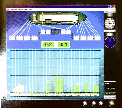
It is not uncommon for LNG terminals to provide the ships with information from various monitoring systems, including:
- navigation and docking systems, which may consist of a portable pilot unit (PPU), approach display boards or wireless pagers that use laser sensors to determine the ship’s speed of approach and the distance off the berth;
- mooring systems that display mooring line loads at individual hooks and the gas carrier’s position relative to the berth fenders and the terminal spotting line. This information can be sent to the ship through the SSL or to a terminal portable computer via a wireless signal. Some systems will allow for a terminal to release mooring lines remotely. However, the design of the release will be such that all moorings cannot be released simultaneously, avoiding the possibility of an uncontrolled release of the mooring lines with consequential damage to the transfer arms and gangway and possible fouling of the propeller and loss of control of the ship, (see ISO 28460 “Installation and equipment for liquefied natural gas – Ship-to-shore interface and port operations” (Reference 2.28));
- meteorological and oceanographic systems that provide information and forecasts on the wind, current, waves, visibility and temperature.
Discussions Prior to Cargo Transfer
Before the start of any cargo transfer operation, the intended cargo handling procedures will usually be thoroughly discussed at a pre-transfer meeting held between the responsible personnel from the ship and the terminal.
The content of the pre-transfer meeting will depend on a wide variety of circumstances, but the following broad outline forms the normal basis for such meetings:
- the names and roles of terminal and ship personnel who will be responsible for cargo transfer operations should be noted;
- the terminal representative should check that pre-arrival instructions to the ship on cargo, cargo disposition and cargo arrival temperature have been carried out and that all necessary ship equipment inspections and tests have been performed;
- the ship’s officers should satisfy themselves that the relevant terminal equipment is satisfactory and that appropriate inspection checks have been carried out;
- the terminal representatives and, where necessary, customs and independent surveyors should be informed of the cargo tank data, including:
- density, temperature and other relevant conditions, including reference temperature;
- pressures;
- cargo tank quantities;
- liquid heel or arrival tank conditions;
- composition of tank vapour;
- total quantity of cargo onboard;
- the cargo transfer operation should be planned and confirmed in writing to help to assure full mutual understanding. The items to be addressed will commonly include:
- the cargo transfer arm connection, leak test, purging and cool-down procedure;
- SSL link tests;
- permission, or not, to continue gas burning mode in engine room (for power generation) during cargo transfer;
- the order of loading or discharging;
- the total quantities of cargo to be transferred;
- the sequence of discharging and receiving tanks;
- critical stages of the transfer operation;
- the intended transfer rates (including topping off rates) and constraints;
- the transfer temperatures and pressures to be expected;
- use of cargo heater or vaporiser;
- the vapour handling method, temperatures and pressures;
- the cargo transfer arm draining, purging and disconnection procedure;
- simultaneous cargo and ballast handling, for stress and ship stability purposes, will commonly be noted on the cargo plan;
- reconfirm any earlier pre-charter advice, the previous three cargoes carried by the ship and the dates of carriage should be noted to identify and assess any possible cargo contamination problems, particularly after the carriage of ammonia;
- the appropriate cargo information and safety data sheets (SDS) should be provided (see article “Personal health and safety crew members on board a gas carrierSafety Data Sheets (SDS)“) and should be posted in prominent places on board the ship and within the terminal. Similar detail for cargo inhibitors, where applicable, should be provided by the terminal;
- a review of port and jetty regulations should be made, including berth operating limits, fire-fighting capabilities and other emergency procedures. Similarly, ship regulations and emergency procedures should be communicated to terminal personnel. Particular importance will usually be paid to ESD valve closure times and to the agreed emergency shutdown procedures;
- equipment and procedures for normal and emergency communications between the ship and the terminal should be defined and understood. Where portable radios are provided, adequate spare battery capacity should be made available. A common language should be established;
- any planned drills;
- any further information or procedures relevant to the operation should be discussed.
Ship/Shore Safety Checklist
The “Revised Recommendations on the Safe Transport of Dangerous Cargoes and Related Activities in Port Areas” (Reference 1.11) refers to a comprehensive ship/shore safety checklist covering the handling of bulk liquid dangerous substances and has a special section for liquefied gases. It includes guidelines for its completion and the current version should always be used.
The ISGOTT ship/shore safety checklist can be found in Section 26 of ISGOTT (Reference 2.4) and consists of:
- Parts A and B (Bulk Liquids – General);
- Part C (Additional Checks – Bulk Liquid Chemicals);
- Part D (Additional Checks – Bulk Liquefied Gases).
For gas carriers, Parts A and D should be fully completed.
A ship presenting itself to a loading or receiving terminal needs to check its own preparations and fitness for the safety of the intended operations. Additionally, the Master will want to assure himself that the terminal operator has also made proper preparations for the safe operation of the terminal.
Similarly, the terminal will check its own preparations and will want to be assured that the ship has carried out its checks and has made appropriate arrangements. The ship/shore safety checklist, by its questions and its requirements for the exchange of various written agreements, is usually the minimum basis for performing such a mutual examination.
Some of the questions in the ship/shore safety checklist are directed to areas for which the gas carrier has prime responsibility. Others apply to both ship and terminal and tho remainder to the terminal alone.
All items lying within the responsibility of the gas carrier should be personally chocked by the ship’s representative and, similarly, all items under the terminal’s responsibility should be personally checked by the terminal representative. In carrying out their responsibilities, both representatives should assure themselves that the safety standards on both sides of the operation are fully acceptable by, for example, questioning the other party, sighting of records and by joint visual inspection. The joint declaration at the end of the ship/shore safety checklist should not be signed until such mutual assurance is achieved.
It will be interesting: Guidance on HAZID and HAZOP for LNG bunkering operations
The conditions under which the operation takes place may change during the process and tho change may be such that safety can no longer be guaranteed. If either party notices or causes any unsafe condition they should take action to reestablish safe conditions, which may include stopping the operation. The presence of the unsafe condition should immediately be reported to the other party and, where necessary, cooperation with the other party sought.
During cargo transfer operations, it is prudent for the items shown on ship/shore safety checklist to be jointly re-inspected at suitable intervals, commonly not exceeding 6 hours, to ensure continued compliance. Whenever such inspections toke place, it is usual for the checklist to be endorsed by ship and terminal personnel as a record.
Guidelines for the completion of the ship/ shore safety checklist have been produced jointly by the oil, chemical and gas industries. These guidelines are also found in Section 26 of ISGOTT and contain detailed advice on each item of the checklist.
All personnel should follow approved safety management system (SMS) cargo handling procedures and may follow any applicable industry best practices to help to reduce casualty risks. Further, it is prudent for personnel to be familiar with all aspects related to the handling of the cargo in question and be aware that cargoes should usually only be transferred/carried within the design parameters of the equipment being used. Any cargo or safety concerns noted prior to or during the transfer operations will usually be communicated immediately to the designated ship and terminal representatives.
Supervision and Control During Cargo Transfer
The responsibility for safe cargo handling operations is shared between the ship and the terminal and rests jointly with the Master and the Terminal Representative. The manner in which the responsibility is shared should, therefore, be agreed between them so as to ensure that all aspects of the operations are covered.
Joint agreement on readiness for cargo transfer operations
Before starting cargo operations, the Responsible Officer and the Terminal Representative should formally agree that both the ship and the terminal are ready to do so safely.
Supervision
The following safeguards should be maintained throughout cargo operations:
- a Responsible Officer should be on watch and sufficient crew should be on board to deal with the operation and security of the ship. A continuous watch of the tank deck should be maintained;
- the agreed ship-to-shore communications system should be maintained in good working order;
- at the commencement of cargo operations, and at each change of watch or shift, the Responsible Officer and the Terminal Representative should each confirm that the communications system for the control of cargo operations is understood by them and by personnel on watch and on duty;
- standby requirements for the normal stopping of cargo pumps on completion of cargo transfer, and the emergency stop system for both the ship and terminal, should be fully understood by all personnel concerned.
Periodic checks during cargo transfer operations
Throughout cargo operations, the ship should monitor and regularly check all full and empty tanks to confirm that cargo is only being transferred to/from the designated cargo tanks. The ship should check tank innages at least hourly and calculate a loading rate. Cargo figures and rates should be compared with shore figures to identify any discrepancy.
On ships where stress considerations may be critical, hourly checks should include, where possible, the observation and recording of the shear forces, bending moments, draught and trim and any other relevant stability requirements particular to the ship. This information should be checked against the required cargo transfer plan to confirm that all safe limits are adhered to and that the sequence of cargo operations can be followed, or amended, as necessary. Any discrepancies should be reported immediately to the Responsible Officer.
Operational Considerations
Berthing and mooring
Berthing
Port and terminal authorities will usually establish berthing and unberthing criteria for safe operations that include limiting wind, wave, current and tide conditions.
Requirements for the number and size of tugs to be used will usually also be established based on marine simulations or operational experience.
Mooring
Liquefied gas terminals will usually have standard mooring plans based on computer analysis for the range of gas carriers that the terminal is designed to accommodate. It is, however, preferable that an analysis specific to ship and terminal is completed. For further guidance on mooring equipment and practices, see the OCIMF publication “Mooring Equipment Guidelines (MEG3)” (Reference 2.57). The initial mooring of the ship to the terminal and the subsequent tending of moorings is a key consideration if the ship is to be safely held alongside and damage to transfer facilities and jetty prevented.
Connection and disconnection of cargo hoses and MLAs
| Example connection and disconnection of cargo hoses and MLAs | ||
|---|---|---|
| № | Photo | Actions |
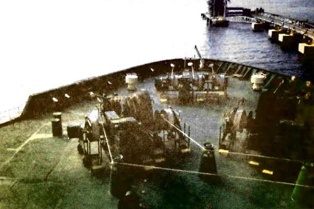
| 1 | 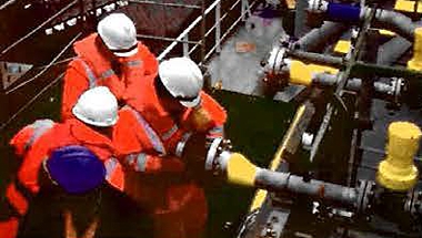 | Flanges will not usually be disconnected or blanks removed until it is confirmed that line connections are liquid free and depressurised and, where applicable, inerted with nitrogen or other suitable inert gas. Core should be taken to avoid air or other contaminants entering cargo pipelines |
| 2 |  | The staff in the manifold region will be limited to essential staff only. The manifold area on oil gas carriers will usually be kept dear of any obstructions that may interfere with the sole automatic release of on MLA. Safe access is to be provided for connecting and disconnecting MLAs/hoses |
| 3 |  | Hose bridging will be restricted to vapour service connections only where permanent systems have been purpose designed. This is sometimes seen on MLAs where vapour return connections are provided by means of piggy-back systems |
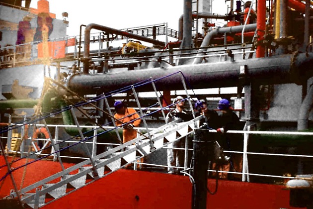
| 4 |  | The manifold area of a gas carrier is a zone where flammable vapours may be present. Therefore, core should be token to ensure that ignition sources are eliminated from this area. PPE should be appropriate for the cargo being transferred and gas detectors should be in good order and calibrated |
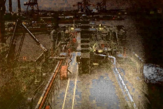
| 5 |  | At some terminals, problems can be encountered with gas comers due to mismatching (in positioning or layout) of MLAs in relation lo the ship’s cargo manifold. As a result it may be necessary to restrict the number of connections used and, thereby, the overall cargo transfer rates |
| 6 |  | Core may need to be exercised that the insulation flange is installed correctly to help to ensure the prevention of any stray current flow (SIGTTO Information Paper “A Justification into the Use of Insulation Flanges (and Electrically Discontinuous Hoses) at the Ship/Shore and Ship/Ship Interface” (Reference 2.71) |
| 7 |  | The cargo manifold supports, distance pieces, spool pieces and reducers will need generally to be capable of withstanding the maximum allowable loads at the presentation flange (see “Manifold Recommendations for Liquefied Gas Carriers” (Reference 2.131, jointly published by SIGTTO and OCIMF) |
| 8 |  | Consideration should be given to terminal QC/DC couplings having differing requirements lo the ship’s presentation flanges (ie spiral groove, flat face, raised face or a combination thereon, to try to prevent leakage at the connection. There may be additional requirements on the maximum internal diameter of the presentation flanges to ensure good contact and positive sealing |
Occasionally you may see references to “non-sparking” hand tools such as spanners. These have typically been made of non-ferrous metal alloys and ISGOTT does not recommend their use, as they are prone to ferrous or other contamination that may render ineffective their “non-sparking” properties.
At some terminals, problems can be encountered with gas carriers due to mismatching (in positioning or layout) of MLAs in relation to the ship’s cargo manifold. As a result, it may be necessary to restrict the number of connections used and the overall cargo transfer rates. An alternative solution involving the use of short lengths of hose or hard piping to bridge the mismatch is unlikely to be acceptable as this could degrade the design parameters and security of the MLA concept.
Cargo handling procedures
Cargo handling is described in article “LPG/LNG loading and unloadingCargo handling operations“, but procedural aspects of these operations directly relevant to the ship/shore interface are considered here.
All operations carried out alongside will usually be under the continuous supervision of experienced ship and terminal personnel, who will, for example, be familiar with the details, hazards and characteristics of the cargoes being handled and capable of ensuring that operations can be safely and efficiently completed. Facilities for instant and reliable communications (such as separate telephone, portable radio or VHF) between the ship and the terminal control will usually be provided at all times during cargo operations.
Before commencing operations, ramping up, maximum cargo transfer rates and ramping down procedures will be agreed in accordance with vapour return specification, ship or terminal vapour handling capacity and emergency shutdown requirements. Inevitably, some of these considerations may be based on best practical estimates so, during operations, it is prudent to maintain a strict watch on flow rates, tank pressures and temperatures. Adjustments can be made as appropriate and by mutual agreement.
If cargo transfer operations need to be stopped, the stopping actions will usually be carried out under previously agreed controlled conditions and with proper communication. If the situation demands an emergency shutdown the agreed procedure will typically be followed, bearing in mind the dangers of excessive surge pressures.
The IGC Code specifies a minimum design pressure of 10 bar for ship’s pipelines, but does not take into account any over pressure allowance for pressure surges. Terminal piping pressure design standards (as detailed in article “Equipment and cargo system of LNG onshore terminalsPipelines and valves – engineering standards ans surge pressure“) do take into account pressure surges. While it is possible to reduce loading rates to keep potential surges within limits, the potential mismatch between ship and terminal piping pressure standards can generally be managed through a high integrity SSL and the ESD system.
Cargo surveyors
Independent cargo surveyors are often employed by cargo buyers or sellers and the survey companies provide personnel to witness cargo operations and check cargo quantities and documentation, both on board ship and within terminals. This may include cargo measuring and cargo sampling (see Reference 2.59).
It is common practice for the independent cargo surveyor, in addition to the ship’s officers and terminal personnel, to maintain a log of events related to cargo transfer operations.
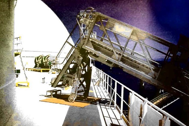
Gangways and ship security
Where possible, the manifold areas will usually be roped off to limit the access of personnel to that area. The gangway will usually be located as close as possible to crew accommodation areas and as far away as possible from the manifold. If the gangway is not fixed to the shore and does not have permanently installed structural handrails, it may need to be rigged with a strong safety net beneath it. On both the terminal and on board ship it is often considered good practice to provide a lifebuoy at the gangway entrances. Proper illumination of the gangway and its approaches will usually be provided during darkness.
A notice warning against unauthorised personnel should be posted at the gangway and provision should be made for all ship visitors to be met and escorted to the accommodation, always in accordance with the appropriate ISPS/MarSec (Maritime Security) and local requirements applicable in that port.
A secondary means of escape from the ship, in case the normal gangway access is unusable in an emergency, will usually be provided. If the jetty configuration renders such secondary escape by gangway impossible, other means may need to be considered. These may include:
- Preparing the ship’s lifeboat for immediate lowering;
- rigging of the ship’s accommodation ladder, as per the ship’s security plan, on the side away from the jetty.
The terminal, in liaison with the ship, should control access to the jetty area to ensure that only authorised persons with legitimate business are permitted access in accordance with the ship and terminal security plans, ISPS/MarSec and local requirements for the particular port. In controlling this access, any relevant local regulations concerning, for example, smoking, carriage of matches or lighters, the use of mobile telephones and pagers and the use of cameras should be complied with.

Similarly, the ship’s deck watch are to check on the side away from the jetty and report the approach of unauthorised waterborne craft coming into the restricted area.
Bunkering
Concurrent bunkering operations of gas carriers (ie bunkering from a barge on the offshore side while simultaneously transferring cargo) may not be permitted by the terminal’s regulations. The risk of a liquefied gas spill at the manifold is higher when cargo transfer is taking place, so if concurrent cargo and bunker operations were underway the bunker barge at the off shore manifold could represent a potential source of ignition.
Concurrent bunkering operations are typically considered to be less of a risk if the bunkers are supplied directly from the terminal through a hose or MLA. However, a full safety and risk assessment will usually be conducted to examine, for example, the availability of competent staff and any conflict with critical operations (topping off, stripping tanks etc.).
If the terminal and the port authority do allow bunkering to take place while the gas carrier is alongside the terminal, the operation will usually be carried out under relevant procedures in the ship’s SMS, and any applicable national and international legislation, which will usually refer to ISGOTT (Reference 2.4).
Work permits
While a ship is alongside, only under exceptional and well controlled circumstances should any hot work (including the use of power tools) be undertaken, either onboard or within the vicinity of the ship. In the event that such work must be carried out, the most stringent safety precautions and procedures should be rigidly adhered to.
To cover these and similar circumstances, a permit to work (PTW) system should be in place. In the event that hot or cold work becomes necessary when a ship is alongside, a work permit will usually be agreed between the ship, the terminal and, where necessary, the port authority. The permit will usually be for a limited duration and will be closed as soon as the work is completed. See also article “Comprehensive Guide to Risk Assessment and Process Safety ManagementPermit to Work Systems (PTW)“.
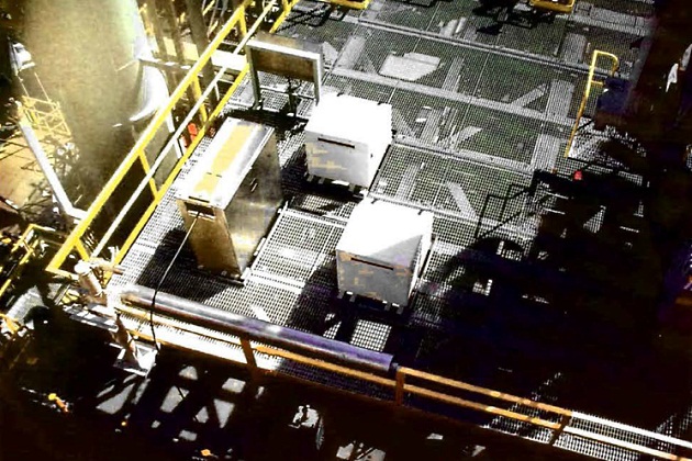
Access to cargo manifold during transfer
Access to the manifold area during cargo transfer will usually be restricted to avoid the possibility of injury if an uncontrolled release of cargo occurs, or the ERS activates. This area will typically be clearly defined and all personnel involved are made aware of the boundaries.
The need to access the manifold area to check pressure and temperature gauges may be eliminated by placing the gauges away from the area.
Fire-Fighting and Safety
When a ship is alongside a terminal jetty a joint fire-fighting and emergency plan will typically be available. The preparation of such a plan is the responsibility of each terminal. The details of the plan will usually consider the appropriate actions to be taken in all envisaged emergencies, including communication with local emergency services and the port authority. A summary of the essential elements within the plan will often be made available to ships’ personnel by way of the terminal information and regulation booklet.
While a ship is alongside the terminal, fire-fighting equipment, both onboard and on the terminal, will need to be correctly positioned and ready for immediate use. Although the requirements of a particular emergency situation will vary, fixed and portable fire-fighting equipment will usually be stationed to cover the ship and jetty manifold area. Fire hoses will usually be positioned and ready for immediate use with nozzles attached, and hoses from fixed dry powder units and portable fire extinguishers should also be positioned and ready for immediate use. In addition, the fixed dry powder monitor will usually be adjusted to protect the manifolds that are in use. The international ship/shore fire connection (see ISGOTT (Reference 2.4)) will typically be available for use at short notice.
Water spray systems should be tested on a regular basis. Where water sprays are designed to operate automatically in the event of fire, it is prudent to test, among other checks, the functioning of the automatic devices.
The ship’s fire control plans will commonly be placed in a watertight enclosure outside the accommodation. This plan should provide the most up to date information. It is generally considered good practice to include an up to date copy of the ship’s crew list in the enclosure.
Linked Emergency Shutdown (ESD) Systems
ESD systems are fitted at terminals and to ships. Linking of the systems is usually accomplished by electrical connections or pneumatic link, although in the LNG trade electrical and fibre optic links are also used. For this system to function properly, both the ship and the terminal need compatible systems. In this regard, typically, plugs, sockets and pin-out configuration will need to be compatible (see “ESD Arrangements & Linked Ship/Shore Systems for Liquefied Gas Carriers” (Reference 2.16)).
The main purpose of a linked ESD system is to enable both ship and shore to activate shutdown of each other’s systems in a safe and coordinated manner during an emergency.
The guiding rules for limiting pressure surge on loading or discharging are commonly considered to be:
- To stop the cargo pump;
- first close the ESD valve nearest to the pump;
- finally, dose other ESD valves.
The guiding rules are generally considered to be standard but the sequence of operations depends on whether the ship is loading or discharging and whether there is good coordination between the ship and jetty. Without a linked system, in an emergency situation control may be difficult and, for this reason, ship and terminal ESD systems will usually be interconnected.
Read also: General Overview of LNG Cargo Tanks (Typical Operations)
Typically, the logic engineered into a linked system will ensure an appropriate procedure is followed no matter which party initiates an ESD. (Details of such a system that may be suited to LPG terminals are available from Reference 2.16. The particular system described in the reference has the advantage of being quite easily retro-fitted to existing plant and ships and is often well suited to the many berths in the LPG trade that are not fitted with them).
Tables 1 and 2 outline the manual and automatic means by which an ESD will typically be activated, including the signals that should be transmitted.
| Table 1. Emergencies that may initiate the ESD | |
|---|---|
| Manual Trip | Manual Trip |
| Operation of manual trip | Operation of manual trip |
| Automatic Trip | Automatic Trip |
| Shutdown signal from shore via link | Shutdown signal from ship |
| overfilling of any cargo tank High-High level | overfilling of receiving tank (import terminal) |
| loss of control air pressure | power loss to arm manoeuvring |
| loss of system pressure in the cargo valve remote control system | power loss to ERS |
| ESD logic failure | ESD logic failure |
| fire at tank domes or manifold area | fire in terminal area |
| loss of electric power | loss of electric power |
| vapour crossover pressure High-High (LNG only) | excessive movement of ship from berth (stage 1 – pre-alarm) |
| vapour header pressure Low-Low | activation of the ERC |
| primary insulation space ∆P out of limits (LNG membrane ships only). | high level in surge drum (where provided). |
See also article “Cargo equipment for gas carriers carrying LNG/LPGEmergency shutdown (ESD) systems“, “Liquefied Petroleum Gas Reliquefaction Plant and Boil-Off ControlShip/Shore Links“, point “Alongside the jetty” above, and “Preparation of loading and unloading operations for LNG/LPG carriersPreliminary procedures“.
| Table 2. Actions that are usually initiated by the ESD | ||
|---|---|---|
| On Ship | On Terminal (Loading) | On Terminal (Receiving) |
| Send shutdown signal to the shore | Send shutdown signal to the ship | Send shutdown signal to the ship |
| trip ship’s cargo, spray and emergency pumps | trip loading pump | start to close terminal ESD valves |
| trip booster pump (LPG only) | open spill-back valves | |
| trip high duty and low duty compressors | start to close the shore ESD valves | |
| start to close the ship’s ESD valves | ||
ESD links are already well established at LNG ports. In the early LNG projects, ship and shore were coupled with pneumatic systems that could be slow in operation and suffered from problems with dirt and moisture. These drawbacks led to the development of electric or electronic and optical links.
In the LPG and chemical gas industry, ESD links may differ from those of the LNG industry. This sometimes causes problems at export terminals with dual purpose jetties capable of accommodating both LNG and LPG carriers, as these terminals often only have an LNG type of link system. Terminals of this type may wish to consider providing an LPG link at these berths, in addition to the LNG link, for use when LPG is loaded. For a detailed description of the ESD links, please see “ESD Arrangements & Linked Ship/Shore Systems for Liquefied Gas Carriers” (Reference 2.16).
Terminal Booklet – Information and Regulation
This chapter has outlined a number of terminal based procedures that may be applicable to ship/shore operations. Many terminals now produce a terminal information and regulation booklet that meets the requirements of OCIMF‘s “Marine Terminal Management Self Assessment (MTMSA)” (Reference 2.55).
Guidelines can be helpful for defining the responsibilities of each party and can be used for introducing local procedures. A booklet of this type may contain, for example, the following items:
Information
- Port geographical position;
- navigational chart to be used for approach;
- restrictions on port entry;
- ship restrictions at the berth;
- weather and tidal data;
- preferred mooring plan;
- diagram of jetty fire-fighting and life-saving appliances;
- procedures for limiting surge pressures;
- terminal pipeline and tankage plan;
- diagram of the jetty MLA arrangement;
- description of ESD arrangements;
- communication methods;
- requirements for a ship/shore ESD link;
- cargo pumping limitations;
- safety requirements;
- emergency procedures;
- environmental requirements (ie vapour release, garbage disposal, port services);
- evacuation routes.
Regulations
Regulations may include national, regional and port authority requirements as well as international standards and guidelines.
Documentation
- Safety letter;
- ship/shore safety checklist;
- cargo planning Form;
- cargo calculation form.
For further information on this subject, see the SIGTTO–GIIGNL ship and terminal database.
Training
Training of seagoing personnel is covered by international regulation under course syllabuses prepared under the auspices of the IMO (References 1.8, 1.9 and 1.1O). See also the following SIGTTO publications:
- “Crew Safety Standards and Training for Large LNG Carriers” (Reference 2.60);
- “LNG Shipping Suggested Competency Standards” (Reference 2.1);
- “LPG Shipping Suggested Competency Standards” (Reference 2.2);
- and “LNG Steamship Suggested Competency Standards for Engineers” (Reference 2.3).
For terminal personnel, similar training may be necessary and in this respect “Marine Terminal Operator Competence and Training Guide (MTOCT)” (Reference 2.53) is published by OCIMF to assist marine terminal managers in determining the competencies and assessment requirements for their marine staff.