LNG carrier pressure relief systems are critical safety features designed to mitigate the risks associated with transporting liquefied natural gas (LNG).
These systems are engineered to release excess pressure that may build up within the cargo containment system during various operational scenarios, such as loading, unloading, or in the event of emergency situations like fire or overfilling. By effectively managing pressure levels, these systems help maintain the integrity of the vessel’s cargo containment structure, ensuring safe and efficient transportation of LNG across oceans and waterways.
Functional Requirements
LNG carrier cargo tanks shall be protected against harmful over-pressure and under pressure as follows:
Cargo tanks to have an emergency over-pressure system which shall
- Be independent of the vapour pressure control system;
- shall be automatically activated and not dependent on the vessel’s power supply for its operation;
- provide for controlled venting, thus not relieve more of the cargo than necessary for limiting pressure rise;
- in case of tanks with more than 20 m3 volume, tolerate at least one valve failure without more than 50 % loss of PRV capacity;
- PRV valves should be so arranged that disabling of their function should not be readily possible;
- PRV valves shall be constructed of materials suitable for the temperatures occurring;
- the valves shall be so located that their function will not be disabled by ingress of liquid cargo with a ship’s list of 15 deg and a trim of 0,015 L or due to liquid expansion when heated;
- the combined relieving capacity of the relief valves for each cargo tank shall be capable of discharging vapour at the rate required by the applied rules with not more than a 20 % rise in cargo tank pressure above the relief valve set pressure.
Cargo tanks to have an emergency under-pressure system which shall
- Be automatically activated and not dependent on the vessel’s power supply for its operation;
- be independent of the vapour pressure control system.
Cargo tanks to have a pressure control system
- Cargo tanks to have a pressure control system keeping the vapour pressure within acceptable limits without venting cargo to the atmosphere during normal operation;
- cargo tanks having a design pressure at least equal to the saturated vapour pressure of the cargo at maximum ambient temperature (45 °C) or, in case of ships intended for short voyages where pressure rise will not exceed the design pressure, a pressure control system need not be fitted.
Design Requirements
Pressure Relief Valve (PRV) function
In general, Liquefied Gas Carrier Typestwo types of PRVs exist. The oldest and most commonly used is the direct acting type. They are designed as direct acting because the force element keeping the valve closed is a weight or a spring or a combination of both. The other type of PRV is the pilot operated type. The primary difference between a pilot and direct acting type is that in the pilot type the process pressure is used to keep the valve closed instead of a weight or spring. PRVs on cargo tanks and hold spaces on LNG carriers are of the pilot operated type. Therefore, further explanations will focus on the pilot type only.
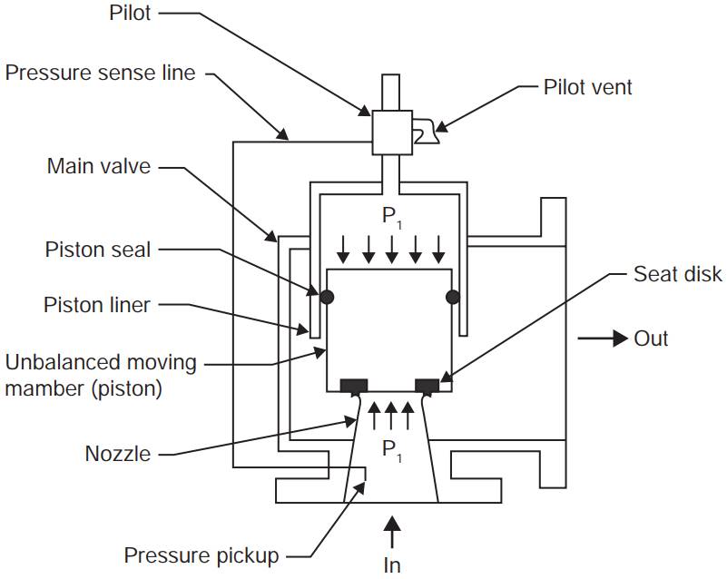
A pilot operated PRV consists of a main valve and a pilot. The basic principle is that the pilot controls the pressure on the top side of the unbalanced moving member. A seat is attached to the opposite side of the member.
- At pressures below set point, the pressure on the opposite sides of the moving member is equal;
- when set pressure is reached, the pilot opens, depressurising the cavity on the top side and the unbalanced moving member strokes upward causing the main valve to relieve;
- when the process pressure decreases, the pilot closes, the cavity on the top is re-pressurised, and the main valve closes.
Pilot design
The design of the pilot for a pilot operated valve must be self actuated, ie it must be actuated by the process pressure. It must also be fail-safe in the open mode.
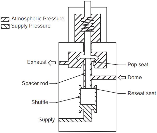
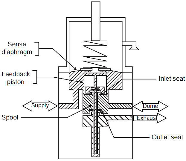
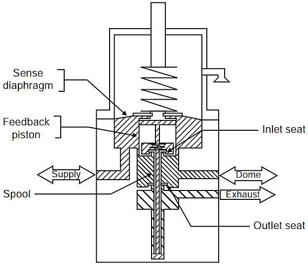
The most common type of pilot design is the no-flow, «pop» action type (see fig. 2 & 3).
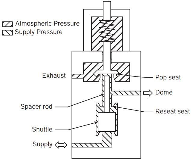
A no-flow pilot is one designed to have no flow of the process gas when the main valve is open and relieving. A «pop» action is one where the main valve rapidly opens at a set pressure to full lift and re-closes at some pressure below set point. The difference between opening pressure and reseat pressure is called blow down and is usually expressed as a percentage. For a set pressure of less than 100 mbar the blow down is to be 10-15 % and over 100 mbar the blowdown is to be 3-7 % (in accordance with SIGTTO 2.2 d).
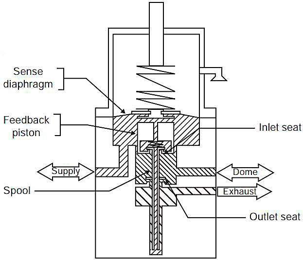
The second most common type of pilot design is the no-flow «modulating» action type (see fig. 4, 5 & 6). This pilot type produces a main valve opening characteristic that is proportional to the relieving capacity required to maintain a given pressure. In this sense, its performance is similar to a back pressure regulator. The pressure at which it opens and closes is approximately the same.
Pressure Settings
Typical pressure set points for a Moss type carrier PRVs would be:
| High pressure alarm in tank: | 220 mbarg |
| Opening of relief valve in tank: | 250 mbarg |
| Low pressure alarm in tank: | 10 mbarg An automatic trip system for the gas compressors, the cargo and spray pumps, IGG, ESD valves and the spray inlet valves are activated when the pressure of any cargo tanks are equal to the atmosphere pressure.x |
| High pressure alarm in hold: | 120 mbarg |
| Opening of relief valve in hold: | 150 mbarg |
| Low pressure alarm in hold: | -20 mbarg |
| Opening of relief valve in hold: | -50 mbarg |
A high differential pressure alarm is activated when hold space pressure exceeds the cargo tank’s pressure by 30 mbarg. An automatic trip system for the gas compressors, the cargo and spray Examples of the Emergency Situations with Liquefied Gas Carrierspumps dedicated to the tank in question, IGG, ESD valves and the spray inlet valves is activated at 40 mbarg of excess pressure in the hold space. In addition, a differential pressure relief valve (for each hold) releases air in the hold space to the atmosphere at 50 mbarg of excess pressure in the hold space.
The cargo tanks PRV would also have possibilities for higher settings as well. The higher settings would be used in case of emergency pressure discharging of the tank.
Read also: Terminal Operations for LNG or LPG Carrier after Arriving in Port
For a typical Membrane type vessel, being Mk III, NO 96 or CS1, the corresponding MARVS (Maximum Allowable Relief Valve Setting) would be:
| Opening of relief valve in tank: | 250 mbarg |
| Opening of relief valve in tank: | -10 mbarg |
| Opening of relief valve in IBS Inter Barrier Spacex | 300 mbarg (Mk III membrane system) |
| Opening of relief valve in IS Insulation Spacex | 350 mbarg (Mk III) |
| Opening of relief valve in IBS | 120 mbarg (CS1 membrane system) |
| Opening of relief valve in IS | 120 mbarg (CS1) |
| Opening of relief valve in IBS | 100 mbarg (NO96 membrane system) |
| Opening of relief valve in IS | 100 mbarg (NO96) |
As the membrane type insulation spaces are purged with nitrogen and are pressure controlled, the vessels are not equipped with any differential or low pressure relief valves in the insulation spaces.