The advent of radio completely transformed maritime communication. Today, radio systems on ships are no longer just a convenience, but a vital lifeline. They ensure safety at sea by enabling critical communication.
At the heart of modern ship radios lies the Basic Concepts of the GMDSSGlobal Maritime Distress and Safety System (GMDSS). This internationally mandated system establishes a standardized framework for distress alerting, safety information broadcasts, and routine communication.
Radio Paths
This topic area deals with the path taken by a radio wave when it leaves the transmitting antenna. The main factor which determines the path taken is the frequency or wavelength of the transmission.
Radio waves travel at the velocity of light, 300 × 106 metres per second. The relationship between the velocity of light (c), frequency (f), and wavelength (λ) is:
- i. e., longer wavelength corresponds to lower frequency, shorter wavelength to higher frequency.
Need for Radio
The radio waves is needed to carry the signal information efficiently and without distortion. In the case of audio frequencies, which may range from about 50 Hz to 15 kHz, it would not be technically feasible to radiate the information directly from a practical transmitter and antenna.
Higher frequencies can be radiated efficiently from antennas having dimensions typically between a quarter and one wavelength. Thus, practical communication systems use a radio wave to carry the audio or other (e. g., vision or data) information between the transmitting and receiving sites.
The Radio Spectrum
Practical transmitter and radiating systems can be realized for radio waves with frequencies above 15 kHz. The radio frequency spectrum is divided into several major band:
- Very Low Frequency (VLF) – 15 kHz to 30 kHz;
- Low Frequencies (LF) – 30 kHz to 300 kHz;
- Medium Frequencies (MF) – 300 kHz to 3 MHz;
- High Frequencies (HF) – 3 MHz to 30 MHz;
- Very High Frequencies (VHF) – 30 MHz to 300 MHz;
- Ultra High Frequencies (UHF) – 300 MHz to 3 Ghz;
- Super High Frequencies (SHF) – 3 GHz to 30 GHz;
- Extra High Frequencies (EHF) – 30 GHz to 300 GHz.
Propagation Mechanisms
Three main physical mechanism govern the propagation of radio waves from transmitter to receiver in maritime radio communications:
- Line-of-sight;
- Ground wave;
- Sky wave.
The relative importance of each mechanism in establishing and maintaining reliable communication by radio depends on the frequency and the distances involved.
Line-of-Sight
Propagation
Above about 50 MHz, propagation is essentially by line-of-sight. This is accomplished, in the case of terrestrial radio, via the lower part of the atmosphere – termed the troposphere – and in the case of space communication via earth-orbiting satellites.
Figure 1 shows a stylised terrestrial radio link. In general, the received signal is the sum of a direct signal along path a, clear of the ground, and several reflected signals along path such as b and c. Because a radio signal undergoes a phase reversal at the reflection point, the theoretical situation is that the direct and reflected signals should cancel out if the receiver antenna is at ground level.
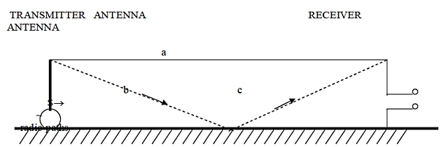
Since land has a poor ground conductivity, total cancellation does not occur in practice, as a simple experiment with a portable VHF FM receiver will show. However, the sea is a very good conductor, which means that maritime VHF antennas should be mounted well above the sea in order to avoid severe cancellation effects.
Ground-Wave
Propagation
In principle, a transmitting antenna sited at the earth’s surface will set up a surface wave which follows the curvature of the earth. The distance over which reliable communication can be achieved by the surface, or ground wave, depends on the frequency and the physical properties (i. e., ground conductivity and dielectric constant) be established with useful efficiency where the wavelength is greater than several tens of metres.
Read also: General Provisions, Rules and Requirements for Safe Carriages of Cargoes
Seawater has highest conductivity and will support the propagation of a ground wave with very little attenuation, in much the same manner as a metal plate. At the other end of the scale, an arid desert provides very lossy ground conditions and will not support the efficient propagation of a ground wave signal.
The significance of this form maritime communications is that long distance working is possible at medium to low frequencies using only modest transmitter powers compared to those for broadcasting at similar frequencies over land.
Sky-Wave
Propagation
Within the frequency range of 1 – 30 MHz, ionospheric reflection is the controlling factor in achieving long-distance communications by radio waves.
Because the ionization processes in the upper atmosphere that is responsible for this effect is caused by the sun, it will be evident that the density of ionization will vary with the time of day and the season of the year. The sunspot cycle, which takes approximately 11 years, also has an effect. Ionospheric storms and other disturbances occur from time to time and – in extreme cases – can cause a communication black-out lasting for some days.
In general, the net result is that, to communicate over a given distance, a higher frequency is necessary when the density of ionization is high and a lower frequency when the density of ionization falls.
The Ionosphere
Long-distance propagation of radio waver at HF is mainly the result of single or multiple reflections from ionized regions in the upper atmosphere known collectively as the ionosphere. These ionized regions are generated at heights of 100 – 400 km (55 – 220 nautical miles) as a result of partial ionization of the molecules making up the rarefied upper regions by ultraviolet and soft (long wavelength) x-ray solar radiation. The ionization process converts the molecules into a plasma of ions and free electrons.
There is a complex variation in the degree of ionization with height such that distinct layers of more intense ionization are formed. The different layers result from different parts of the ultraviolet spectrum. The heights of these layers vary from day to night and with the seasons.
The most important layers for long-distance propagation of radio waves are:
- the E-layer at 120 km;
- the F1 – layer at 200 km;
- the F2 – layer at 300 – 400 km.
At night and at mid-winter the F1 and F2 layers combine to form a single F-layer at 250 km. This is a result of a gradual recombination of the ions and electrons back into the atmospheric gas molecules during the night.
Below the E-layer is the D-layer, at a height of 50 – 90 km, which also has an influence on propagation, but more as an absorber of radio waves than as a reflecting layer.
However, at VLF and LF frequencies the D-layer is sufficiently reflective to guide signals between the ground and the bottom of the D-layer for several thousand kilometres with little attenuation.
Ionospheric reflection may be simply described as the phenomenon whereby a wave appears to undergo reflection on reaching a suitably ionized region. Free electrons are set in motion so as to re-radiate the wave in a changed direction. At it passes through the ionized layers, the wave may eventually be reflected back to the earth. On a simplified view the effect may be viewed as reflection from an area at what is termed the mirror height.
The effect is frequency-dependent, with a greater degree of ionization being necessary to cause reflection as the frequency is increased. Usually the higher layers have the greater degree of ionization and therefore reflect the highest frequencies. Because of the greater mirror height, the communication range achieved by a single reflection will also be greatest under these circumstances.
The solar radiation responsible for ionizing the atmosphere varies continuously from day a night and between the seasons. Sunspot activity also has a strong underlying effect on the degree of ionization. The level of sunspot activity varies over a cycle of around 11 years, with periods of maximum ionization occurring when the number of sunspot is at a maximum.
Normally, the variation is predictable enough for the best frequency bands to be selected for the intended communication path without difficulty.
Ionospheric Disruptions
HF communications can, however disrupted by ionospheric storms for several days at a time when eruptions on the sun’s surface emit a stream of high – energy charged particles which then obliterate the ionized layers – the F-region in particular. Auroral displays in the polar regions often accompany these events.
Ionospheric storms are often preceded by sudden ionospheric disturbances (sids) when intensely strong bursts of ultraviolet radiation from the sun produce intense ionization of the low D-layer. When sids occur, waves are absorbed in the D-layer before reaching the higher layers or are reflected over much shorter distances than usual, with the result that long-distance communications will be blocked for hours at a time.
Circuit Reliability
In normal circumstances the selection of the optimum frequency for establishing and maintaining communications is governed by the following considerations.
Maximum Usable Frequency
The maximum frequency which is reflected by the ionosphere over any particular path is known as the maximum usable frequency (MUF).
The MUF depends on:
(a) time of day;
(b) season;
(c) latitude;
(d) period of sunspot cycle.
The MUF varies according to which layer is responsible for reflection back to the earth. For each layer, the highest MUF is obtained when the ray path leaves the earth tangentially, so that the ray approaches the appropriate layer at as oblique an angle as possible. As shown in Figure 2, this corresponds to an overall ground-to-ground distance of about 4 000 km (2 200 nautical miles) for F2-layer propagation (path A); or 2 500 km (1 300 nautical miles) for E-layer (path B). Any rays leaving the earth at a higher angle of elevation (path C) will penetrate the layer and not be reflected. To use such ray angles, with consequently shorter path, it is necessary to reduce the operating frequency (path D).
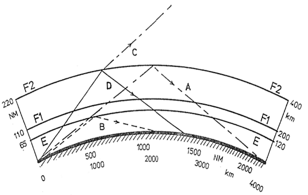
In general, the strongest signals (i. e., those with least attenuation) will occur using frequencies just below the MUF, for the particular path distance and layer involved.
When a wave is sent vertically upwards (see Figure 3), the highest frequency for which reflection by any particular layer will occur is termed the critical frequency, f0.
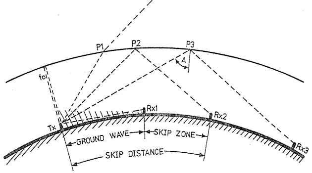
This frequency is much lower than the MUF = f0/cos A is the angle of incidence of the ray to the layer. At frequencies higher than f0, the waves will penetrate the layer and be lost, but as the angle of radiation is progressively lowered an angle be reached where reflection occurs (termed the critical wave angle). Signals can then be received at a great distance (receiver R × 2 in Figure 3), and radiation at lower angles will be reflected to even greater distances (e. g., receiver R × 3).
At points nearer to the transmitter no signals will be received by ionospheric reflection, but when sufficiently close to the transmitter (receiver R × 1 in Figure 3) to be within range of the ground wave the signals will again be heard. In between there is an area of very poor reception, termed the skip zone. The distance from the transmitter to the nearest point at which a wave at a particular operating frequency returns, after reflection, back to the earth (receiver R × 2) is known as the skip distance.
When the frequency is less than the critical frequency f0 there will, of course, be no skip at all. This situation is often found for frequencies below 8 MHz.
It will be interesting: Basic Knowledge of Hazard Controls
The critical wave angle for a particular layer depends on the operating frequency and decreases as the frequency increases. In consequence, the skip distance increases with frequency. The MUF therefore represents a limit which must not be exceeded for the receiver to remain in the area of reception just beyond the skip zone. The result is that the skip distance extends towards the receiver as the operating frequency approaches the MUF. The reflecting layer also absorbs HF radiation, and this effect decreases markedly as the operating frequency approaches the MUF.
The combined effect is that, for any particular radio circuit, the optimum working frequency lies just below the MUF for the particular path. Any rise in operating frequency or fall in MUF will result in a sudden drop-out of received signals as the skip zone extends to include the reception point.
Lowest Usable Frequency
As the operating frequency is reduced, the reflection will occur in the lower layers of the ionosphere. However, at lower altitudes, and in the D-layer especially, the energy in the wave is subject to increased absorption caused by collisions between air molecules and electrons which are set in motion by the radio wave. The effect increases at lower frequencies, and the limit for any particular path is reached at the lowest usable frequency (LUF).
While the MUF is determined solely by the physical properties of the ionosphere, the LUF also has dependence on the radiated power and the receiver sensitivity over the circuit, and can be controlled to an extent by attention to optimizing equipment and antenna performance – hence the need to keep both equipment and antennas in good condition.
Single – Hop Condition
An HF radio circuit can also be set up by multiple reflections between the ionosphere and the ground. Variability and absorption increase with each reflection (or hoop), so single-reflection (hop) path, as described above, is to be preferred for maximum circuit reliability.
To avoid multiple – hop conditions it is advisable to aim for the MUF for the highest ionospheric layer, in the expectation that this will normally exceed the MUF for the lower levels and thereby avoid multiple reflections involving the lower layers.
Optimum Traffic Frequency (OTF)
Ionospheric absorption is much less at night than during the day and therefore the attenuation of the lower HF frequencies is very little different from that of higher frequencies during the day. Since the MUF at night over a particular path will generally be less than half the daytime figure, this means that for night-time long-distance communications it is possible to maintain considerably lower frequencies and still achieve good reliability.
The MUF for a particular path is higher during the summer months than in the winter months, but during ionospheric storms the MUF may become much lower for transmissions in some directions but higher in other directions.
In planning the optimum traffic (or working) frequency for any particular time, season, distance and direction, it is therefore necessary to take all of these variations into account.
At any particular time, a sky-wave path is available on channels in a window below the MUF and above the LUF. The MUF is defined by the prevailing ionospheric conditions, but the LUF is set by a combination of path loss and equipment parameters such as transmitter power, noise and receiver antenna performance. In practice, the first choice of working frequency for sustained circuit reliability would be around 85 % of the MUF.
The MUF can be predicted on a long-term average basis. The variations in MUF can be up to a third higher or lower on a “normal” day-to-day basis and, in disturbed conditions, the MUF can be less than half the predicted value.
The LUF is typically about half the MUF for maritime HF equipment, but this can vary considerably.
Under normal conditions, the window of available frequencies varies predictably as follows:
- daytime MUF is higher than night-time MUF;
- winter MUFs are both lower than and vary more than summer MUFs;
- radio circuits less than 1 000 km (600 nautical miles) normally use frequencies bellow 15 MHz;
- radio circuits greater than 1 000 km (600 nautical miles) normally use frequencies above 15 MHz;
- and MUFs are higher when the sunspot number is high.
Frequency bands and propagation
The relationship of the different propagation mechanisms to the different frequency bands is outlined below.
VLF
The radio wave follows the curvature of the earth’s surface and is known as a ground wave. The range of a ground-wave signal is governed by the rate of loss of energy into the ground, which in turn is governed by the value of ground conductivity. The attenuation of the ground waves is least over seawater and greatest over dry rocky ground or deserts.
VLF signals are reflected well by the D-layer of the ionosphere and, because the height of the D-layer is of the same order of wavelengths at VLF, the net effect is of a waveguide for VLF signals between the ground and the D-layer. The signal attenuation is very low under these conditions and transmission paths up to 12 000 nautical miles are possible.
Large antenna arrays are normally used at VLF with very high output transmitter powers (750 kW) to give virtually world-wide coverage. VLF transmissions are therefore only used in the shore to ship direction. VLF signals penetrate the sea to a depth of a few tens of metres, making them very effective for maintaining communications with submerged submarines.
LF
At LF, ground-wave propagation predominates, as with VLF, but, due to the higher frequency, the range is reduced, particularly over land, due to the relatively greater attenuation effect of poor ground conductivity as the wavelength is reduced, particularly over land, due to the relatively greater attenuation effect of poor ground conductivity as the wavelength is reduced. The wave-guide effect between the ground and the D-layer still applies at LF, and conditions are, in fact, more stable than at VLF. There is also an improvement as regards lower background noise levels at LF. However, the path attenuation is higher.
Ranges of one two thousand nautical miles are possible at LF but, again, large antennas transmitter output powers are required.
MF
MF communications also depend mainly on ground-wave propagation but with a futher reduction in range because of the increased effect of attenuation by the earth. However, sky-wave propagation starts to become significant at MF, particularly at night, greatly extending the range. This can be a negative effect, however, owing to mutual interference between stations on the same frequency, and interference fading caused by signals arriving at the receiver by different paths from the transmitting station.
A coast station can achieve good ground-wave coverage for voice communications up to 300 nautical miles. Ship stations, with less powerful transmitters and less elaborate antenna systems, can usually expect reliable ground-wave communications up to 150 nautical miles for voice communications and 300 nautical miles for DSC/telex.
HF
In practice, a good guide to establishing reliable communication at HF is to monitor the telex Most coast stations emit an “idling” signal on their HF telex channels when no traffic is present.x (NBDP) channels of the wanted coast station on the more likely bands for the time of day and season and then to call the station on whichever band provides a strong stable signal. If this in not successful, the other bands should be tried. The ionosphere can behave erratically at times and, on occasion, reception is better in the Ship/shore interface for safe loading and unloading of LNG/LPGship-to-shore direction than in the shore-to-ship direction or vice versa. Communication is frequently unreliable around sunrise and sunset.
The considerable variability of radio communication at HF is a consequence of signal propagation being predominately by sky wave, both day and night. A ground-wave signal is still present but attenuates too rapidly to be value for reliable commercial communications.
The D-layer of the ionosphere has little effect above 4 MHz and long-distance propagation is by reflection from the E– or F-layers. In general terms, the higher the HF band used, the greater the range. This is because the higher the frequency, the further the wave has to pass into the ionosphere before it undergoes sufficient bending to be returned to earth. To a first approximation, therefore, the situation is that the higher the frequency, the greater will be reflection (mirror) height and so the greater will be the potential range.
Long-range propagation is also possible as a result of multiple reflection between the ground, the ionosphere and even between the layers of the ionosphere itself. However, these modes of transmission are very variable and would not be used intentionally for normal commercial communications.
The best policy for reliable HF communications is to use the highest frequency consistent with the length of the radio circuit using a single reflection. The angle at which a radio wave enters the ionosphere is also an important factor, with reflection occurring at a lower height for oblique incidence compared to vertical incidence (see Figure 3).
The highest frequency which can be used to communicate between two fixed points by sky-wave propagation is known as the maximum usable frequency, MUF. Since this frequency puts the receiver on the edge of the skip distance, it is better to use the lower frequency of 0,85 × MUF, termed the optimum traffic frequency, in order to improve reliability. Note, however, that theh preferred choice of channel may already be in use.
For example, to establish communications with Portishead Radio (United Kingdom) during the daytime, the following would apply:
- 3 MHz = N. France;
- 6 MHz = N. Spain;
- 8 MHz = N. Africa;
- 12 MHz = Ghana;
- 16 MHz = Angola;
- 22/25 MHz = South Africa.
At night, due to changes in the ionosphere, the situation changes as the F1 and F2 layers merge and the heights of the E and F layers fall. The general result is tahta, to cover the same range at night it is necessary to halve the operating frequency; e. g., a link from Portishead to Capetown during daytime is possible on 22/25 MHz, but during the night the 12 MHz bands would be the first choice.
When transmitting east-west, the signal may pass from daytime to night-time conditions, and it may be very difficult to establish effective communications. One strategy is to estimate the optimum transmission band according to the day/night conditions at the midpoint of the radio circuit. The best course of action may be to wait until the entire path between the two stations is in daylight or darkness.
Read also: GMDSS carriage requirements and basic provisions
Above 50 MHz the predominant propagation mechanism is by straight-line paths, i. e. line-of-sight.
For satellite communications an unobstructured view of the satellite is required, and the Ship Earth Station antenna must mounted to achieve the best view possible.
For terrestrial communication the range depend upon the heights of both the transmitting and receiving antennae.
Because of a slight bending effect on radio waves in the troposphere, caused mainly by water vapour, the radio horizon is in fact greater than the optical horizon by a factor of 4/3.
Taking this factor into account, the maximum range at sea is given by the formulae:
where:
- Tx and Rx are the heights of the transmitting and receiving antennae above sea level, measured in feet or metres as indicated.
Figure 1 also shows a surface wave S propagating over a terrestrial radio link. In principle, the received signal will be the sum of the line-of-sight signals and the surface wave. In practice, however, one or other of the two components will predominate depending on the transmission frequency and length of the radio link. Ground-wave propagation predominates at MF, LF and VLF.

- General operator’s Certificate for The Global Maritime Distress and Safety System, Course + Compendium, Model Course IMO 1.25, Printed by PMS UK Ltd London, 2004.
- European Radiocommunications Committee ERC Decision of 10 March 1999 on the harmonised examination syllabi for General Operator’s Certificate (GOC) and Restricted Operator’s Certificate (ROC)(ERC 99 01).
- IMO GMDSS-Handbook, London, U. K., 2004.
- Norcontrol Capella GMDSS Simulator, Technical documentations, Kongsberg Maritime Ship Systems, Norway, 2005.
- INMARSAT MARITIME COMMUNICATIONS HANDBOOK – INMARSAT – London, U. K, 2005.
- Seafarers’ Training, Certification and Watchkeeping CODE 1995 (STCW Code 95, published by IMO, London, 1996), – Part A Mandatory standards regarding provisions of the annex to the Convention Chapter IV Standards regarding radio personnel.
- Seafarers’ Training, Certification and Watchkeeping CODE 1995 (STCW Code 95, published by IMO, London, 1996), – Part B Mandatory guidance regarding provisions of the STCW and its annex; Chapter IV Guidance regarding radiocommunication and radio personnel.
- V. Pipirigeanu, M. Udrea, Introducere in GMDSS – Sistemul Mondial de Primejdie si Siguranta Maritima, Ed. Europolis, Constanta, 2002.
- Graham D. Lees, William G. Williamson, Handbook for Marine Radio Comunication, e d. LLOYD S OF LONDON PRESSLTD., 2004.
- ITU Manual for Use by The Maritime Mobile and Maritime Mobile Satellite Services, 2006.
- IAMSAR Manual – International Aeronautical and Maritime Search and Rescue Manual, 2001.
- C/S G.003 – Introduction to Cospas-Sarsat System, (G3OCT28.99D Issue 5 – Rev 1 October 1999), C/S Documents published by Cospas-Sarsat in Handbook of Regulations on 406 MHz and 121,5 MHz Beacons, (1999);
- Tor R. Kristensen – An Introduction to GMDSS, revised GOC Edition, – 7th edition, Leknes, Norway, 2007.
- C/S T.001 – Specification for Cospas-Sarsat 406 MHz Distress Beacon, (T1OCT30.99D – Issue 3-Rev. 2 October 1999), Documents published by Cospas-Sarsat in Handbook of Regulations on 406 MHz and 121,5 MHz Beacons (1999).
- IMO SOLAS (SAVE OF LIVE AT SEA), Consolidated Edition, London, 2001.