This article covers the following learning outcome: outline the hazards, risks and controls available for safe containment of hydrocarbons offshore and onshore.
- Hazards and risks including overfilling, effects of vacuum, overloading of foundations and failure modes for tank shells and associated pipework
- Storage tanks
- Evolving damage mechanisms
- Mechanical damage
- Floating roof tanks, landing the roof, sinking the roof and rim seal fires/failures
- Introduction
- External floating roof tanks
- Internal floating roof tanks
- Issues with floating roofs
- Fixed roof storage tanks, pressure and vacuum hazards
- Fixed roof tanks
- Bunding of storage tanks including volume and area sizing, construction and valving arrangements
- Bunding of tanks
- Filling of tanks, overfilling/alarms/tanker connections
- Transfer of product
- Transfer of material between road/rail tankers and tanks
- Pressurized/refrigerated vessels for Liquefied Petroleum Gas (LPG), Liquefied Natural Gas (LNG) and carbon dioxide (CO2)
- Liquefied Petroleum Gas (LPG) storage
- Liquefied Natural Gas (LNG) storage
- Carbon dioxide (CO2) storage
- Loss of containment and consequences
- Jet fires
- Pool fires
- How hydrocarbon vapour clouds are generated and their potential consequences
- BLEVEs, CVCEs and UVCEs
- BLEVE – Boiling Liquid Expanding Vapour Explosion
- Confined Vapour Cloud Explosion (CVCE)
- Unconfined Vapour Cloud Explosion (UVCE)
- Pipelines, their protection, surveying, maintenance, security against arson and illegal tapping
- Decommissioning of plant and associated facilities
- REVISION QUESTIONS FOR ELEMENT 3 CONTINUED
Hazards and risks including overfilling, effects of vacuum, overloading of foundations and failure modes for tank shells and associated pipework
Storage tanks
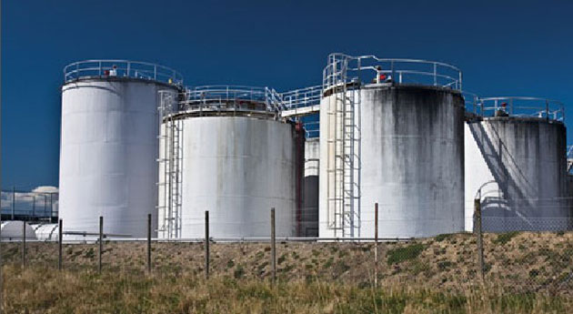
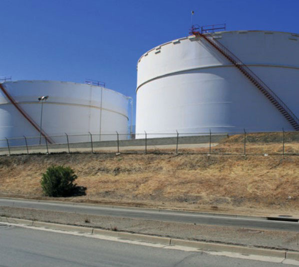
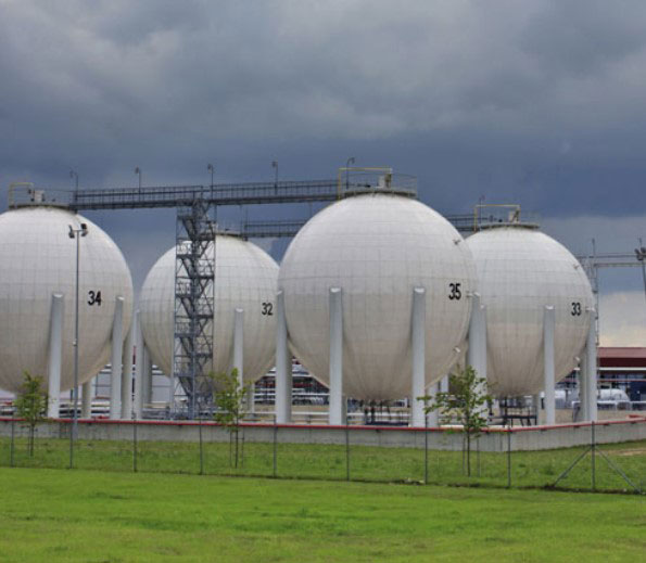
Hydrocarbons are usually stored in tanks like those shown in Figure 1 below. Depleted wells and salt caverns are also used as storage facilities.
However, for the purposes of this module we will be concentrating solely on storage in tanks.
The type and quantity of the product being stored will dictate the type of tank used, as well as the measures used to control the risk of it failing. For instance, gases such as propane may require refrigerated or pressurized storage, whereas oils can be stored in standard storage tanks like those shown below. However, the quantity of oil to be stored, together with the oil’s particular volatility, are factors which will also govern the type of tank to be used.
Source: iStock. Storage tanks – capacity
Storage tanks – capacity
Tanks may be quite small (e. g. 1 000 m3) or very large (e. g. 50 000 m3). Consequently, the foundation on which the tank is built should be substantial enough to take the weight of the tank when full. However, this is not a straightforward calculation as the density, or specific gravity, of oil varies from approximately 0,8 tonnes per m3 to 1,3 tonnes per m3 depending on its type and grade.
Furthermore, it is not just the capacity of the foundations that determines the amount of product that can be stored. The particular design and construction of the tank shell, along with its support structure, will also be a consideration.
Each tank will have a prescribed maximum volume although, as we’ve mentioned, the density of oil varies greatly depending on its type and grade and this prescribed volume may have to be reduced accordingly for that reason.
During a storage tank’s life, the quantity of product in the tank will need to be carefully monitored and this can be done manually by sight gauge, or remotely with gauges that feed back to a central control room. As a secondary measure, these signals are usually linked to an alarm system which will warn of any exceptionally high or low levels.
The risk of overfill is greatest when product is being pumped into the tank from another source, such as a road or sea tanker transporter. The overfill alarm system may well have an auto-shutdown facility, but this is not always the case and dependency on such devices is not recommended as they can fail. Consequently, good communications and standardized procedures between the party sending the product and the recipient is essential.
Storage tanks – integrity management
Storage tank integrity is an important aspect which needs to be well managed and controlled. This is because these tanks contain large amounts of hazardous liquid which, if it leaked, could result in a catastrophic event.
Tanks are often thought of as simple structures that require little attention, and for this reason arrangements generally are not as robust or comprehensive as for other process plant and equipment. Nevertheless, storage tanks can deteriorate in complex and varied ways.
Another consideration is the compatibility of the product being stored with the material the storage tank is made from. Not all products are compatible with all materials and knowledge of what product can be stored within tanks of a specific material is essential. Also, as we’ve mentioned, the specific gravity of oil differs from type to type and this will affect the safe operating level of the storage tank.
The following management practices, which are regarded as good practice with regard to managing storage tank integrity, are taken from the HSE document “Integrity of Atmospheric Storage Tanks”.
- Tanks containing hazardous substances should be identified and entered in the plant register;
- Operators should maintain tank data files;
- Compatibility assessments should be undertaken (e. g. tanks on multi-product service);
- Tanks should be subject to formal periodic maintenance and inspection;
- Inspection and maintenance of tanks should only be carried out by experienced and qualified competent persons;
- Schemes of inspection should be established and agreed between operators and competent persons;
- Appropriate inspection techniques should be utilized, depending on deterioration mechanisms;
- Inspection reports and checklists should be of high quality;
- Where necessary, recommendations from inspection reports should be actioned promptly;
- Assessment of fitness for service should be carried out following tank inspection and significant changes to process or operating conditions;
- Operators and competent persons should have knowledge of, and adopt the recommendations given in, the relevant guides, codes and standards;
- Tank examination schemes should include both internal and external inspections.
Evolving damage mechanisms
There are many types of evolving damage mechanisms which can affect storage tanks, many of which can work simultaneously.
They include the following:
- Corrosion;
- Erosion;
- Creep associated with non-metallic thermoplastic tanks;
- Fatigue;
- Chemical attack;
- Brittle fracture.
We will now take a more detailed look at each of these evolving damage mechanisms.
Evolving damage mechanisms – corrosion
Corrosion is the gradual deterioration of a substance by way of a chemical reaction with its immediate environment. Corrosion is most commonly associated with rusting, which is when metal reacts with oxygen to form iron oxide. This is a form of electromechanical corrosion.
Most storage tanks are made from carbon steel, which makes corrosion a primary cause of deterioration. Furthermore, corrosion can occur both internally and externally, which makes the monitoring of corrosion a difficult issue.
Tanks known as “flat bottomed tanks” are particularly prone to corrosion on the underside of the top plate as well as the upper side of the base plate. This tends to be aggravated if the product being stored is experiencing an aqueous phase (aqueous meaning water present within the product). Product temperature is also an important factor in the amount and rate of corrosion.
Other factors which can affect corrosion in the base plate are:
- The materials used in construction;
- The condition and the effectiveness of the floor-to-base seal;
- The angle of the tank pad away from the base of the tank.
The floor of a “flat bottomed tank” may not be flat. This is because most are cone-shaped so that water and other bottom products can be allowed to gravitate to a point where they can be drawn off. Cone-up bottoms have sumps around the edge of the tank to take bottom products away, whereas cone-down bottoms have a sump in the middle to do the same job.
Bottom products often contain aggressive compounds, and the monitoring of the pH of these products may be regarded as good practice in monitoring and controlling corrosion.
As well as top and bottom plates, corrosion of the lower part of the shell strake, or wall, is a common feature. This may be caused by rainwater being allowed to settle around the tank base. One means of controlling this, apart from ensuring there is good drainage away from the tank, is to paint the bottoms and lower section of the tank wall with a protective coating.
We mention in Types of Failure Modes that may lead to Loss of Containment from Hydrocarbonsarticle the issue of annular rim failure, and it’s worth repeating part of that issue here because of its relevance.
Annular plates are prone to corrosion attacks both on the outer side where the tank shell sits on the annular rim and on the underside of the annular plate where trapped water may lie undetected. This corrosion, coupled with the prolonged stress, can lead to stress corrosion cracking and failure occurring without warning.
Drains and draw-off sumps used to transport water and bottom products away from storage tanks are also vulnerable to corrosion, and this is compounded by the fact that they are difficult to inspect, and the culverts they lie in are often submerged in rainwater.
Other areas of corrosion are as follows:
- Where fittings are welded to the tank shell;
- Potential water traps, e. g. below wind girders, stairwells and stairway connections;
- Liquid/vapour interfaces;
- Around breathers and vents.
Another common form of external corrosion is Corrosion Under Insulation (CUI). Here the temperature of the stored product is a critical factor. Some products have to be stored within a range of 50-100 °C and, as such, the tank needs to be insulated. When this is coupled with one or both of the compounding factors given below, an ideal environment for corrosion is created.
The two aggravating factors referred to above are:
- If the insulation material is high in chlorides, this will increase corrosion;
- If the insulation material is not cut away on the bottom edge it will lead to a “wicking effect”. This is where moisture is drawn up from floor level and retained within the insulation.
Control measures for Corrosion Under Insulation (CUI) are as follows:
- Use low chloride or chloride free insulation;
- Vulnerable areas, such as the roof-to-shell joint, should be effectively sealed;
- Fit supports for the insulation;
- Apply small-bore penetrations to the insulation to allow moisture to escape;
- Ensure the lower 20-25 cm of the tank shell is free of insulation.
When undertaking maintenance or inspections, extreme care must be taken when walking on a tank roof, as its integrity cannot be taken for granted. Also, internal floating roofs tend to be of very lightweight construction and, as such, are not suitable for people to walk on.
Evolving damage mechanisms – erosion
Erosion is the process of material being worn away by the constant movement of product flowing over the surface. Areas such as filling and discharge points which experience large amounts of product flow are the most vulnerable points.
The main control measure for erosion is to increase the thickness of the material where erosion is identified as a threat.
Evolving damage mechanisms – creep associated with thermoplastic tanks
Creep is where the tank material stretches over a period of time when it is under stress from the weight of the product being stored. However, this condition only affects non-metallic thermoplastic tanks.
Increases in temperature tend to compound the problem with High-Density Polyethylene (HDPE) being particularly vulnerable and losing its strength as the temperature increases.
Evolving damage mechanisms – fatigue
Pressure vessel storage tanks are more prone to fatigue defects than tank storage vessels. This is because the membrane stresses in pressure vessels are much greater.
For tank storage vessels which are subject to a cycle of frequent filling and emptying, certain parts of the tank’s construction can be vulnerable, particularly welded joints.
Read also: Common Hazards and Risk Assessment in Oil and Gas Industry
Control measures revolve mainly around inspection and monitoring so that any problems can be detected and dealt with before they become an issue.
Dye penetration testing and other non-destructive testing techniques can be used to detect fatigue-induced defects.
In Glass Reinforced Plastic (GRP) tanks, fatigue is a recognized feature and a defined service life for these tanks is standard.
Evolving damage mechanisms – chemical attack
As we mentioned earlier, the compatibility between the product being stored and the material of the storage tank is paramount. If this is not the case, then there is a possibility of deterioration due to chemical incompatibility. Materials stored at elevated temperatures may need additional consideration, as the aggressiveness of some products is greater at these increased temperatures.
The most common materials used in the construction of storage tanks are carbon steel, stainless steel and Glass Reinforced Plastic (GRP). Carbon steel is suitable for a large number of products, although some products with an acid content may react with carbon steel.
Stainless steel is used where purity of the stored product is paramount. However, welded areas in stainless steel tanks can be prone to stress corrosion cracking.
Glass reinforced plastic suffers from ultraviolet light degradation over time and has a reduced ability to perform as product temperature is increased.
Evolving damage mechanisms – brittle fracture
Brittle fracture tends to be most prevalent either during hydro-testing shortly after construction has been completed or during the first filling in cold weather. If these two events have been successfully completed, then experience shows further risk of brittle fracture is minimal.
Mechanical damage
Mechanical damage can be inflicted on storage tanks in many ways, including:
- Impact;
- Settlement which is non-uniform;
- Over-pressurization;
- Vacuum;
- Excessive external loads such as snow, ice and rain, where the load has not been allowed to drain away;
- Wind loads;
- Tanks floating off from their foundations.
Let’s take a look at each of these issues.
Mechanical damage – impact
An impact on a metal tank will have a distorting effect which can compromise tanks with floating roofs. Non-metallic tanks have poor impact resistance and may well fracture if the impact is serious.
Control measures include placing barriers in areas where impacts may occur. Similarly, bunding may act as a protective barrier. Good inspection regimes will also pick up on externally inflicted damage.
Mechanical damage – settlement which is non-uniform
Subsidence can be caused by constant weight on weak or compressible terrain. The weakness or compressibility may not be uniform, which can lead to distortions in the tank structure. Foundations which are designed and built to compensate for local conditions are essential.
Two further causes of foundation movement are frost heave, where the ground is subject to frequent freezing and thawing, and ground movement caused by high tides in areas close to the sea.
A precautionary measure where these factors are recognized as issues is to fit connecting pipes with flexible joints or bellows to allow for movement.
Mechanical damage – over-pressurization
Over-pressurization is where pressure is allowed to build up to unacceptable levels and can lead to a tank rupture. This is most likely to happen when the tank is being filled and the pressure relief valve fails. Controls include regular inspection and maintenance of these valves and any sensors associated with them.
Mechanical damage – vacuum
Vacuum generally affects fixed roof storage tanks. As the tank is gradually emptied of product, if the relief valve or vent becomes blocked or fails, a vacuum will build up causing the tank to distort. Again, controls include regular inspection and maintenance of these valves and vents together with any sensors associated with them.
Mechanical damage – excessive external loads
The most common external loads which can cause damage to a storage tank are snow and ice. These can cause buckling where the loads are excessive and should be cleared before they cause problems.
Rainwater can also be an issue, especially on floating roofs where drains have become blocked.
Mechanical damage – wind loads
Wind can cause tanks to lift, especially if they are not anchored down or have little product in them.
Mechanical damage – tanks floating off their foundations
Tanks are surrounded by bunds. These serve the purpose of containing product if there is a leak. However, in a situation where rainwater is allowed to build up inside a bunded area with a tank in it which has not got a lot of product within it and which has not been anchored down, it is possible for the tank to float off its foundations.
Controls are to keep bunded areas free of rainwater by pumping it out on a regular basis. There are specialized pumps available now called “bund water control units” which monitor the rainwater collected within the bund and automatically pump it to an onsite interceptor. These units also have an automatic oil detection function which will shut down the pump if oil is detected and send an alarm signal to the control room.
Floating roof tanks, landing the roof, sinking the roof and rim seal fires/failures
Introduction
Storage tanks play a major part in the oil and gas industry, where large amounts of hydrocarbons have to be stored at various stages of their process to become a useable product, or are awaiting transportation for final distribution.
As we mentioned earlier in this article, storage tanks come in many different sizes and designs, and the size and design is dictated by the quantity and type of product they are expected to store.
There are tanks which have a fixed roof and those which have a floating roof. We will look at those tanks with floating roofs first.
Tanks with floating roofs can have an “internal floating roof” or an “external floating roof”.
Storage tanks with what are known as “external floating roofs” have a containment cover which floats inside the shell walls, but is open to the elements.
Storage tanks with an internal floating roof still have a containment cover which floats inside the shell walls, but has a roof covering over the outer shell.
External floating roof tanks
An external floating roof tank is made up of a cylindrical shell with a fixed base. This shell then has a roof within it which floats up and down on top of any liquid stored within the tank. This means that there is no vapour space – known as ullage – in a floating roof tank. This lack of ullage in a floating roof tank reduces product loss due to evaporation. A rim seal between the roof and the inner tank wall also ensures evaporation is kept to a minimum.
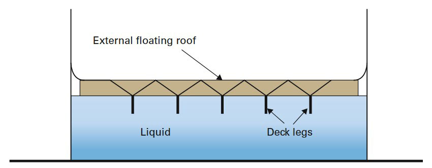
Source: Wise Global Training
The exception to this is that, if there is a very low level of liquid in the tank, the legs on the underside of the roof will engage with the base and a void will evolve. This is an aspect called “landing the roof”, and we shall be looking at this later in this section.
The main disadvantage of an external floating roof is that snow can accumulate on the roof and can build up to such a level as to cause the roof to sink. The same can happen with rainwater if the drain from the roof becomes blocked. Also, the rainwater on the roof is usually drained through a hose which passes through the stored product to a drain valve in the base of the tank. If this hose develops a leak, it will drain both rainwater and product.
Internal floating roof tanks
An internal floating roof tank uses the same principle as an external floating roof but the tank then has a fixed roof covering the tank, as shown in Figure 3 below.
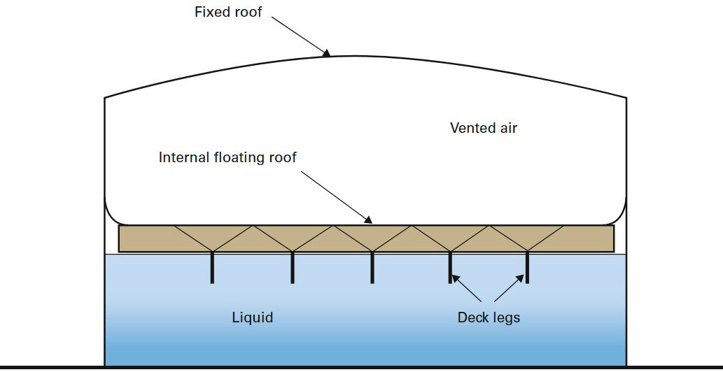
Source: Wise Global Training
Aspects relating to internal floating roofs tanks are as follows:
- The internal floating roof tends to be made of a very lightweight construction and, as such, is not suitable for people to walk on;
- Internal floating roof tanks are free venting. That is to say, they are not fitted with Pressure and Vacuum Valves (P&Vs);
- Internal floating roof tanks tend to be used for storing material with a low flash point, such as gasoline.
Issues with floating roofs
There are issues to be considered with both types of floating roof system. These include:
- Landing the roof;
- Sinking the roof;
- Rim seal failures and rim seal fires.
We will now look at these issues and their ramifications.
Issues with floating roofs – landing the roof
Landing the roof is where the liquid in the tank falls far enough for the legs on the underside of the floating roof to land on the base of the tank. The void between the liquid and the roof will grow, which will allow a build-up of vapour to occur. This has the potential to cause a fire and/or an explosion.
If the roof is landed, it is important that enough time elapses before the tank is refilled to allow the space below the roof to become saturated with vapour so that it exceeds its upper flammable limit. This is because when product is pumped into the tank and the roof begins to lift, there is a chance that a spark may be generated between the tank wall and the roof seal. Having the vapour in the ullage saturated to beyond its upper flammable limit will ensure the vapour will not be ignited by any errant spark. The amount of time required to allow the vapour to become saturated may be as much as 24 hours.
Another issue with landing the roof is that it causes a particular corrosion mechanism called fretting-related corrosion. This is where repeated contact with the base of the tank by the legs on the underside of the floating roof tends to remove protective layers of rust scale from the base that may have formed over time. This has the effect of increasing corrosion rates at these locations.
Issues with floating roofs – sinking the roof
Sinking the roof can be caused when the roof becomes unbalanced for some reason and sinks into the liquid.
Reasons for becoming unbalanced include:
- Build-up of rain or snow;
- Use of access ladders on one side of the roof;
- In certain parts of the world, earthquake activity may have a destabilizing effect on the roof.
With internal roofs, if the roof sinks the ullage space will quickly fill with flammable vapours and create a fire/explosion hazard. However, the volatile atmosphere will be contained within the tank beneath the fixed roof.
With external roofs, if the roof sinks, the flammable vapours are free to evolve and drift away and may meet a source of ignition.
Issues with floating roofs – rim seal failures
Floating roofs move up and down within the shell of the tank according to the level of liquid in the tank. The space between the tank wall and the roof is kept airtight by a rim seal which ensures vapours don’t escape, and contaminates such as rainwater don’t get into the stored liquid.
Most systems have a double seal so that there is a back-up in place should the primary seal fail. Furthermore, there is usually a detection system built onto the roof so that if a leak does occur, it can be detected and dealt with. The detection system may well incorporate an automatic rim seal fire-fighting system as well.
Without these safety features, vapours could escape unnoticed. In such cases there have been occasions where an electrical storm has created a set of circumstances which have created a spark adjacent to the tank. This has subsequently ignited the vapour and caused a fire.
All tanks should be well earthed and lightning conductors erected to prevent lightning striking the tank. They should also be frequently checked for earth continuity.
Fixed roof storage tanks, pressure and vacuum hazards
Fixed roof tanks
Fixed roof tanks can either be self-supporting or have internal supports for the roof.
Fixed roof tanks undergo numerous loads and pressures during their working life and understanding what these loads and pressures are, and the circumstances in which they occur, is an important part of controlling the hazards they generate.
The weight of any liquid pumped into a tank will naturally apply outward pressure on the walls of that tank. Also, as the liquid builds up inside the tank, the atmosphere in the void needs to be vented out. If this does not happen the pressure will become unsustainable and the tank may rupture.
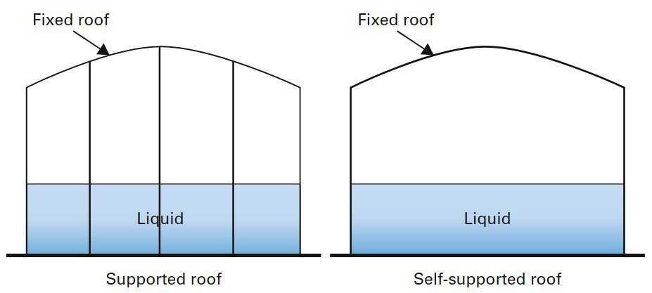
Source: Wise Global Training
The contra view is also true, in that when a tank is emptied the liquid reduces and the void above the liquid needs to have air vented in so that a vacuum is not created. If the air inlet valve is faulty, and a vacuum is created, this may well cause the tank to collapse.
There are other factors which can cause increased or decreased pressure within the tank. These include:
- Storing a volatile product will cause gases to evolve and increase pressure;
- Warm weather or direct sun on the tank will warm the product up and make it expand, thus increasing pressure;
- Cold weather will cool the product down and cause it to contract, thus decreasing pressure.
Normally, tanks have a Pressure and Vacuum (P&V) relief valve fitted on or near the top of the tank. This allows vapour or gas to escape or, in the case of a reduction in pressure within the tank, allows air to enter the tank. This ensures the integrity of the tank is retained.
Consequently, the P&V relief valve is a critical piece of equipment and the integrity of the tank is dependent on it working properly, and as such it should be regularly inspected and maintained.
Another method of controlling changes in pressure is to employ an expansion or pressure exchange system. This is where the expelled vapour or gas is directed to another tank rather than to atmosphere. Where a vacuum has to be dealt with, the system draws in an inert gas from an external source.
This system ensures volatile gases or vapours are not released to atmosphere in an uncontrolled fashion.
Bunding of storage tanks including volume and area sizing, construction and valving arrangements
Bunding of tanks
Where storage tanks hold a liquid product there is always the possibility that the tank will rupture and spill its contents. Consequently, contingencies should be in place to control such a situation. This is where a containment wall, known as a bund, is built around a tank, or group of tanks, to contain any spillage that may occur until such time that it can be dealt with.
The bund also stops the product spreading too far, seeping into the ground, or seeping into the drainage or water systems. It also reduces (although it does not eliminate) the risk of fire and/or explosion.
We have listed below some of the effects and consequences of a tank failure which is not contained by a bund.
Environmental effects
- Contamination of the surrounding ground area;
- Contamination of water courses should the spill reach public sewers and/or drains;
- Impacts on wildlife and aquatic life;
- Evaporating fuel from the spill having an effect on the ozone layer.
Consequences and effects
- Fire (impingement on other plant and equipment);
- Explosion;
- Uncontrolled release of a substance which may be toxic;
- Health risks to personnel on site;
- Contamination with other products;
- Damage to neighbouring businesses;
- The risk to personnel onsite;
- The risk to personnel offsite (local residents);
- Flooding into catchment ponds, interceptors, etc. and reaching public sewers, drains and waterways;
- Business shutdown, loss of revenue, loss of company good name and image.
Bunds are designed to contain any spillages and stop them escaping. This includes seeping into the ground. Consequently, bunds should be built on an impervious base and the material the bund is constructed from should also be impervious.
A bund needs to contain any amount of spillage from the tank(s) it surrounds. Therefore, the capacity of the bund must be equal to the total maximum content of the tank(s) within the bund plus an extra 10 %.
The bund itself must be complete, that is to say it must not be breached. Any pipelines must go over the bund rather than through it. Access to the tanks inside the bund must again be over the bund rather than through a gate.
Source: Dreamstime
There should also be some sort of high level alarm warning system on the bund linked to the central control room to warn the control room operators of any leaks. Should a spillage occur, arrangements must be in place to deal with it. Similarly, arrangements must be in place to remove rainwater which may accumulate within the bund.
Removal of rainwater can be a costly process, as the water may be classed as hazardous waste due to its potential contamination with product. However, there are specialized pumps available now called “bund water control units” which monitor the rainwater collected within the bund and automatically pump it to an onsite interceptor. These units also have an automatic oil detection function which will shut down the pump if oil is detected and send an alarm signal to the control room.
Source: Dreamstime
Tanks can be individually bunded, or bunded as a group. However, where tanks are bunded as a group, it is important to ensure that products within the tank grouping will not conflict with one another if they leak at the same time.
Finally, the bund wall should be substantial enough to maintain its integrity if a fire occurs.
Filling of tanks, overfilling/alarms/tanker connections
Transfer of product
The transfer of product from one location to another comes with its own inherent hazards. Any transfer operation has the potential of leakage or overfill, and measures must be taken to minimize such risks. We are going to look at transfers involving storage facilities. Transfers can be from road or rail tankers to a storage facility, or vice versa. They can also be from a marine tanker to a storage facility, or vice versa.
Transfer of material between road/rail tankers and tanks
The safe transfer between road/rail tankers and tanks should include:
- Securing the road/rail tanker – brakes applied, and engine turned off;
- Ensuring that hoses are suitable for the product being discharged and the operating pressures they will be subjected to;
- Ensuring the connections of pipes and hoses to be used in the transfer operation are secure;
- Positioning of drip trays beneath all connections and ensuring there is close monitoring of connections during transfer operations;
- Making a good bonding connection between the road/rail tanker and the loading/unloading equipment. This will ensure that both the tanker and loading equipment have the same electrical potential;
- Making ready fire control measures, such as fire-fighting equipment, before transfer commences;
- Noting emergency escape routes before transfer commences;
- Closely monitoring the flow rates and fill capacities. This will include alarm systems to indicate when tanks are nearing their filling point;
- Having adequate venting arrangements in place to ensure vapour is dispersed properly and safely. This will include monitoring wind direction and strength;
- Low wind speed can be an added hazard, as the dispersion of vapour in these conditions is minimal and it can build up in dangerous quantities without being apparent. If there is an ignition source nearby, the results can be catastrophic;
- Having venting arrangements to the recipient tank in place as well as similar arrangements for the donor tank as air, or more likely inert gas, will have to replace the volume of product transferred.
Bottom loading of road tank
Petroleum tanker filling via low level connections provides operators with the potential to load multiple compartments simultaneously as well as having automatic high level alarm for each compartment.
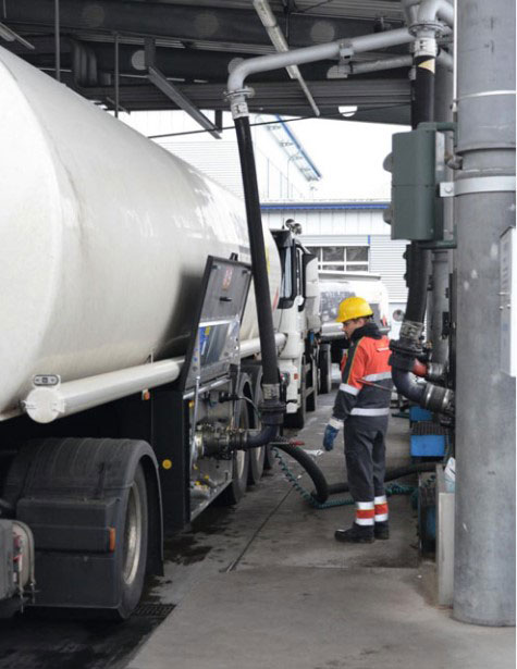
Source: Loadtec Engineered Systems Ltd.
Tankers can also be top loaded, as can be seen in Figure 8.
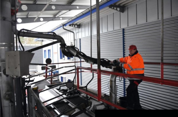
Source: Loadtec Engineered Systems Ltd
Pressurized/refrigerated vessels for Liquefied Petroleum Gas (LPG), Liquefied Natural Gas (LNG) and carbon dioxide (CO2)
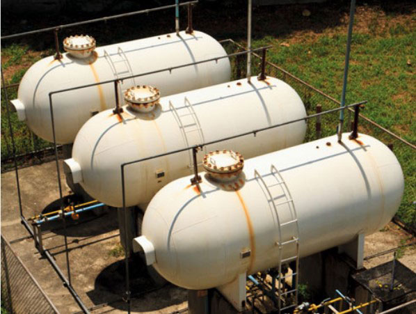
Liquefied Petroleum Gas (LPG), Liquefied Natural Gas (LNG) and carbon dioxide (CO2) all require specialized pressurized/refrigerated/insulated storage facilities in order to keep the product contained and safe. These tanks are likely to be cylindrical or spherical in shape as the laws of physics dictate that these shapes are the most efficient when it comes to containing high pressure gases.
Their construction is on a massive scale, with walls being up to 15 cm thick in order to contain the high pressure. However, there will be a pressure relief valve situated at the top of each tank which will be set to automatically operate if pressure builds up to a level near to the tank’s maximum safe working limit.
We shall now look in more detail at individual requirements demanded by different products.
Liquefied Petroleum Gas (LPG) storage
As we mentioned in Common Hazards and Risk Assessment in Oil and Gas Industrythis article, to store Liquefied Petroleum Gas (LPG) effectively, it has to be converted from a gas to a liquid, which means it is stored at a temperature of between 0 °C and -44 °C. Apart from the containment of pressure within the tank, the other main safety issue is that any moisture which settles to the bottom of the tank will need to be drained off, and there is a risk that this water will freeze within the drain valve whilst it’s in an open position, allowing LPG to escape.
Source: Dreamstime
This can be overcome with the use of a multi-valve drainage system together with an established procedure and sequence for opening and closing the valves to drain water. Finally, only fully trained and authorized personnel should be allowed to implement this procedure.
Liquefied Petroleum Gas (LPG) containers that are subjected to fire of sufficient duration and intensity can undergo a boiling liquid expanding vapour explosion (BLEVE). Consequently, LPG spheres should be protected by a fire water deluge system and this will have to be supplemented with an adequate fire water runoff system.
Large, spherical liquefied petroleum gas containers may have wall thicknesses of up to 15 cm. Furthermore, they will ordinarily be equipped with an approved pressure relief valve.
Liquefied Natural Gas (LNG) storage
As we mentioned in Common Hazards and Risk Assessment in Oil and Gas Industrythis article, Liquefied Natural Gas (LNG) needs to be stored at -162 °C in order to maintain its liquid state. This effectively reduces its volume 600-fold.
Storage tanks that are designed to store liquefied natural gas have double skins, with the inner skin containing the LNG and the outer skin containing insulation materials.
Source: Dreamstime
Liquefied natural gas is kept in its liquid state by maintaining very low temperatures. The temperature within the tank will remain constant if the pressure is kept constant. However, some of the liquefied natural gas will naturally change back to its gaseous state and this will be released from the tank under an operation known as auto-refrigeration.
Carbon dioxide (CO2) storage
Liquid carbon dioxide (CO2) storage tanks usually have a storage capacity range from 3 000 kg to 50 000 kg. The vessels can be horizontal or vertically mounted. They have an inner steel tank cloaked by a layer of 175 mm insulation, and are covered with aluminium cladding.
Loss of containment and consequences
Loss of containment is the one single event which has the greatest potential for catastrophic consequences, including loss of life and plant. Understanding what can happen to that product once it is released is therefore essential in implementing controls to mitigate the effects.
To this end, we will now be looking at the following issues:
- Jet fires and pool fires;
- How hydrocarbon vapour clouds are generated and their potential consequences;
- Boiling Liquid Expanding Vapour Explosions (BLEVEs), Confined Vapour Cloud Explosions (CVCEs) and Unconfined Vapour Cloud Explosions (UVCEs);
- Pipelines, their protection, surveying, maintenance, security against arson and illegal tapping.
Jet fires
A jet fire is where a fire emanates from a source of fuel which is being continuously released in a particular direction with significant force.
Jet fires can arise from a release of either a pure flammable liquid or from a gaseous flammable liquid. Figure 11 shows a typical jet fire.

Source: Dreamstime
Jet fires are a significant element of the potential consequences of a major offshore accident. The characteristics of a jet fire mean it can engulf objects with a high temperature flame almost instantly, which can lead to structural failure of vessels or pipework and a possible escalation of the situation.
Furthermore, because jet fires develop almost instantly, they are difficult to control or isolate.
The properties of a jet fire depend on a number of variables. These include the type of fuel, the rate of fuel being released, the velocity of release, the direction of release and the local wind direction and strength.
As we mentioned, jet fires reach full intensity almost instantly. However, the contrary is also true in that they can be turned off quickly if the source of fuel can be terminated. This is an important characteristic when control and isolation strategies have to be considered.
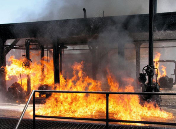
Pool fires
A pool fire is a fire which burns above a horizontal pool of vaporizing hydrocarbon fuel.
Pool fires can be static, where the pool of fuel remains in one position, or they can be running fires where the pool of fuel runs like a river. These characteristics pose a serious risk, especially where installations have large liquid hydrocarbon inventories. Figure 12 shows a typical pool fire.
Source: iStock
How hydrocarbon vapour clouds are generated and their potential consequences
Any release of flammable liquids or gases can result in the formation of a cloud of flammable vapour which, as it is likely to be more dense than the surrounding atmosphere, will stay at a low altitude as opposed to rising and dispersing in the upper atmosphere. If the cloud then meets a source of ignition, and it is within its flammability limits, it will result in a fire or explosion.
Depending on the characteristics of the incident, this may be a flash fire, a fire ball or a vapour cloud explosion. If the vapour cloud still extends back to its original source, it could result in a jet fire or pool fire.
Under certain conditions, the speed of the front of the flame may move to a supersonic level, resulting in a significantly more powerful explosion.
BLEVEs, CVCEs and UVCEs
The abbreviations listed below are all types of explosion related to vapour clouds:
- BLEVE – Boiling Liquid Expanding Vapour Explosion;
- CVCE – Confined Vapour Cloud Explosion;
- UVCE – Unconfined Vapour Cloud Explosion.
We will now look at what each of these situations involves.
BLEVE – Boiling Liquid Expanding Vapour Explosion
Any vessel which is partly filled with pressurized hydrocarbon liquid (e. g. liquefied petroleum gas) will have a certain amount of space above it filled with vapour. If the vessel is subjected to a fire, the pressure in the tank will increase due to the liquid going above its boiling point and turning into a vapour.
The pressure relief valve will allow the overpressure to be vented to atmosphere in the first instance, but this will reduce the amount of liquid in the tank still further and the potential for the flame to engage with a section of the tank containing vapour and not liquid will increase. If this happens, the tank wall will weaken at this point as the heat transfer to vapour is much less efficient than to a liquid.
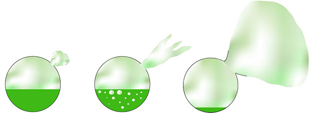
Source: Wise Global Training
The result is likely to be a sudden and catastrophic failure of the vessel, with a discharge of vapour followed by an explosion when it reaches the flames. This, in effect, is a boiling liquid expanding vapour explosion.
Confined Vapour Cloud Explosion (CVCE)
A Confined Vapour Cloud Explosion (CVCE) is an explosion following a leak of vapour which occurs in a confined space, such as a building or a tank.
Where the confined space is totally confined, a vapour cloud explosion would generate approximately 8 bars of pressure. Most buildings would not be able to withstand this level of overpressure unless there was some venting. The venting could be a deliberate design feature (an explosion panel) or unintentional venting (a window or door giving way under the pressure).
A confined vapour cloud explosion inside a tank may cause the tank to rupture, with the potential for missile damage in the form of flying debris from the fragmented tank causing damage and injuries, and possibly fatalities.
Unconfined Vapour Cloud Explosion (UVCE)
An Unconfined Vapour Cloud Explosion (UVCE) is an explosion following a leak of vapour which occurs in an unconfined space (outdoors).
The actual process of what happens when an unconfined vapour cloud explosion takes place is as follows:
- There is an initial and highly rapid expansion of burnt gas (fire ball);
- This initial expansion of burnt gas (fire ball) produces a flow of unburnt gas ahead of it;
- The flow of unburnt gas ahead of the flame front generates turbulence when obstacles are encountered;
- This turbulence increases the flame area and with it, the burning velocity. This then increases the speed of the flame front as it passes through any obstacles. In effect, this increases the size of the explosion;
- The increase in flame speed increases the volume of the fire ball as well as the flow of unburnt gas ahead of the flame;
- At this point, we have an almost self-serving situation where the combustion-driven flow increases turbulence which increases the rate of combustion. Under these circumstances, it is quite possible for flame speeds to reach the order of the speed of sound.
An example of an unconfined vapour cloud explosion was the Flixborough disaster (see Figure 14).

Source: Getty Images
Pipelines, their protection, surveying, maintenance, security against arson and illegal tapping
Oil and gas pipelines carry large amounts of product over vast distances. They are the most efficient means of distributing product and the safest, although if and when there is a breach in a pipeline, the quantity of product lost can be significant. Statistics show that accidents involving trucks carrying oil or gas are 3 000 times more likely to occur than with a pipeline, 38 times more likely by barge and 25 times more likely by rail.
Pipelines are manufactured from steel or plastic tubing which can vary, depending on the volume required to be transported, from 10 cm to 120 cm thick. They are generally buried underground at depths of between 1 and 2 metres. The momentum of the oil is maintained by pump stations situated at regular intervals along the pipeline’s length. These locations can also serve for Remote Terminal Units (RTU) which feedback information on the pipeline’s dynamics as well as service points for inserting and recovering Pipeline Inspection Gauges (PIGs).
Because of the high volumes of product involved, and once flow through a pipeline stops, it stops completely, pipelines need to be surveyed and maintained to the highest standards.
Surveys, inspections and maintenance activities can be carried out using pipeline inspection gauges. These devices are inserted into the pipeline at special insertion points and can perform various operations including inspections, cleaning and other maintenance operations. Some devices can even measure pipe wall thicknesses and the extent and location of any corrosion. They can perform all these operations without having to stop the flow of product in the pipeline.
The insertion and removal of PIGs can be a hazardous operation because of the high pressure of product in the pipeline. Consequently, strict safe working procedures need to be established and implemented at the PIG receiving and launching station.
PIG receiving and launching stations are generally ancillary loops in the pipeline which allow the PIG to be received in a trap or launched at a launching point. Figure 15 shows a drawing of a typical PIG receiving and launching station.
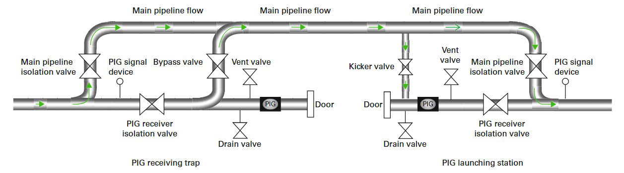
Source: Wise Global Training
The following is an outline of the procedure for receiving and removing a PIG.
PIG removal
- Once the PIG is detected as being in the receiving station by the PIG signalling device, the PIG receiver isolation valve and the bypass valve are closed;
- The drain valve is opened to allow product in the now isolated receiving trap to depressurize and drain off;
- The vent valve is opened to allow the PIG receiver pressure to be vented down. At the same time, nitrogen is introduced into the receiving station in order to purge the receiver of hydrocarbon vapours. This is a most important aspect, as air mixed with hydrocarbon vapours would create a potentially explosive situation;
- Once the operator is satisfied that all product has drained out of the receiving station and it is fully purged, the receiver door can be opened and the PIG removed.
Now we have covered PIG removal, we can look at how a PIG is launched. Just like receiving and removing a PIG, launching can also be a hazardous operation. The following is an outline of the procedure for launching a PIG.
PIG launching
- The kicker valve and the PIG launcher isolation valves are closed in order to isolate the launch station section;
- The drain valve is opened to allow product in the now isolated launch station to depressurize and drain off;
- The vent valve is opened to allow the PIG launch station pressure to be vented down. At the same time, nitrogen is introduced into the launch station in order to purge the station of hydrocarbon vapours;
- Once the operator is satisfied that all product has drained out of the launch station and it is fully purged, the launch station door can be opened and the PIG inserted;
- The launch station door is now closed and the station is now re-purged with nitrogen;
- The kicker valve is opened to introduce product back into the pipeline;
- The launch isolation valve is now opened, allowing the PIG to advance into the main pipeline.
Pipelines can be damaged by trailing anchors under the sea and trawling activities. Deliberate damage can come from arson or terrorist attacks or from illegal tapping.
Security devices are available which can monitor pipelines that are land-based or sub-aqua based. These work using fibre optics and can monitor both pipeline security and leak detection.
On land-based systems, they can monitor both underground and over ground pipelines. As well as leaks, they will detect any activity being undertaken on the pipeline and relay its location back to a control room or security centre.
Sub-aqua systems are capable of detecting leaks and even diver activity within the vicinity of the pipeline.
Land-based pipelines which are situated underground should also have their location identified above ground with milestone markers. This is to help protect against damage from activities such as excavations, etc.
Decommissioning of plant and associated facilities
Decommissioning of an installation and its associated facilities involves planning, gaining approval for, and implementing the removal and disposal or reuse of the installation once it is no longer required for its current purpose.
There are five distinct stages in the decommissioning process:
- All options for the physical dismantlement and/or removal of the installation are assessed and the best option is selected. This is then put through a detailed planning process involving all engineering, safety and environmental aspects;
- Production/extraction is stopped and all the wells are plugged;
- The installation is dismantled and/or removed in line with the agreed plan of action;
- Those parts of the installation that have been removed are disposed of or recycled;
- A seabed survey is carried out to ensure nothing untoward has happened to the original location of the installation. If any part of the installation remains, ongoing monitoring will be implemented.
There are strict international, regional and national guidelines and regulations regarding the decommissioning of oil and gas installations. These have to be taken into account at the very beginning of the decommissioning process when planning is under way. Most installations will either be reused at another location or recycled in some way.
Deciding on the best decommissioning process carries the highest degree of responsibility and care. It involves balancing the demands of providing an economic solution with protecting the environment, the health and safety of those involved in the decommissioning process, the technological issues involved, other users of the sea in the vicinity of the location and any regulatory or legal considerations.
The key to safe decommissioning is ensuring that rigorous and wide ranging risk assessments are conducted which encompass all the work involved in the decommissioning process. From this, safe systems of work will evolve and these should be observed and adhered to.
Management of simultaneous operations
Simultaneous Operations (SIMOPS) or activities can be described as a period in time when more than one operation or activity is being conducted at the same time with the potential that these activities could clash and bring about an undesired event or set of circumstances.
It is important that all work being undertaken at the same time, or which overlaps within a specific time frame, is identified before that work commences. It is then possible to review all activities and see where any conflict might occur.
It is not just the physical activities that need consideration, the demand for resources, or the termination of energy sources, may also cause conflict which could create unwanted situations.
Prior to any work commencing, the parties involved in the operations which are going to be conducted within a shared timeframe should each draw up a risk assessment of all their anticipated activities, including any constraints or hazards associated with those activities. They should then draw up a list of the corresponding measures which will mitigate those hazards that have been identified.
The parties should then meet to discuss the extent of their work and their requirements. The intention of the meeting is for each party to be able to draw up a work-specific dossier which covers how their activities will be conducted whilst taking into account all the other parties activities and avoiding any conflict.
The meeting should resolve the following issues:
- The extent of the responsibilities of each party;
- Nomination of a responsible person for each party;
- Ensuring that responsible persons know of each other and have contact arrangements in place;
- Identifying the requirements of each party;
- Identifying the time frame of the actual work activity of each party.
Compliance with procedures and good communications, including handover procedures, should be adhered to as standard.
Where permit-to-work systems are ongoing, they should take into account any conflict that simultaneous operations might create. They provide, amongst many other things, for the control of work activities that may interact or affect one another. They also provide a management facility where two or more individuals or groups need to co-ordinate activities to complete the job safely.
With regards to the permit-to-work system in place at the time of the Piper Alpha disaster, there was no cross-referencing when the work carried out under one permit might affect the work under another. Reliance was placed entirely on the memory of the designated authority. This practice has since changed so that permits-to-work do, as a matter of course, take into account other activities which may be affected.
REVISION QUESTIONS FOR ELEMENT 3 CONTINUED
Answer 1
Erosion is the process of material being worn away by the constant movement of product flowing over the surface. Areas such as filling and discharge points, which experience large amounts of product flow, are the most vulnerable points.
Answer 2
Normally, tanks have a pressure-vacuum relief valve fitted on or near the top of the tank. This allows vapour or gas to escape or, in the case of a reduction in pressure within the tank, allows air to enter the tank. Consequently, the pressure-vacuum relief valve is a critical piece of equipment and the integrity of the tank is dependent upon it working properly.
The weight of any liquid pumped into a tank will naturally apply outward pressure on the walls of the tank it is being stored in. Also, as the liquid builds up inside the tank, the atmosphere in the void needs to be vented out. If this does not happen the pressure will become unsustainable and the tank may rupture. The contra view is also true in that when a tank is emptied the liquid reduces and the void above the liquid needs to have air vented in so that a vacuum is not created. If the air inlet valve is faulty, and a vacuum is created, this may well cause the tank to collapse.
There are other factors which can cause increased or decreased pressure within the tank. These include:
- Storing a volatile product will cause gases to evolve and increase pressure.
- Warm weather or direct sun on the tank will warm the product up and make it expand, thus increasing
pressure. - Cold weather will cool the product down and cause it to contract, thus decreasing pressure.
Answer 3
Landing the roof is where the liquid in the tank falls far enough for the legs on the underside of the floating roof to land on the base of the tank. The void between the liquid and the roof will grow, which will allow a build-up. of vapour to occur. This has the potential to cause a fire and/or an explosion. Another issue with landing the roof is that it causes a particular corrosion mechanism called fretting-related corrosion. This is where repeated contact on the base of the tank by the legs on the underside of the floating roof removes protective layers of rust scale that may have formed, resulting in increased corrosion rates.
Answer 4
If the roof is landed, it is important that enough time elapses to allow the space below the roof to become saturated with vapour so that it exceeds its upper flammable limit. This is because when product is pumped into the tank and the roof begins to lift, there is a chance that a spark may be generated between the tank wall and the roof seal. Having the vapour in the ullage saturated to beyond its upper flammable limit will ensure the vapour will not be ignited by any errant spark. The amount of time required to allow the vapour to become saturated may be as much as 24 hours.
Answer 5
Where storage tanks hold a liquid product there is always the possibility that the tank will rupture and spill its contents. Consequently, contingencies should be in place to control such a situation. This is where a containment wall, known as a bund, is built around a tank, or group of tanks to contain any spillage that may occur until such time that it can be dealt with. The bund also stops the product spreading too far, seeping into the ground, or seeping into the drainage or water systems. It also reduces (although it does not eliminate) the risk of fire and/or explosion.
Answer 6
A BLEVE is a Boiling Liquid Expanding Vapour Explosion. An example of how a BLEVE might develop is when a vessel is partly filled with pressurized hydrocarbon liquid (e. g. Liquefied Petroleum Gas). It will have a certain amount space above it filled with vapour, and if the vessel is subjected to a fire the pressure in the tank will increase due to the liquid going above its boiling point and turning into a vapour. The pressure relief valve on the tank will allow the overpressure to be vented to atmosphere in the first instance, but this will reduce the amount of liquid in the tank still further, and the potential for the flame to engage with a section of the tank containing vapour and not liquid will increase. If this happens, the tank wall will weaken at this point as the heat transfer to vapour is much less efficient than it is to a liquid. The result is likely to be a sudden and catastrophic failure of the vessel, with a discharge of vapour followed by an explosion when the vapour reaches the flames. This is a Boiling Liquid Expanding Vapour Explosion (BLEVE).